Boiler Superheater Design Modification
•
7 likes•3,334 views

The document summarizes the failure history and root cause analysis of the superheater tubes in two high pressure boilers. The superheater tubes experienced premature failures due to overheating, with surface temperatures reaching 550-600°C. Analysis found the superheater design had too low pressure drop, inadequate steam velocities, and lack of screen tubes. Modifications reduced tube count, implemented a double stage design with attemperation, upgraded metallurgy, and increased pressure drop. The modifications eliminated overheating failures and improved performance.
Report
Share


Boiler Superheater Design Modification
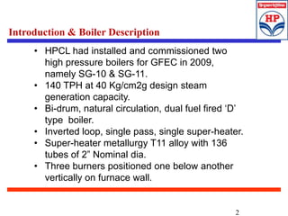
- 2. 2 Introduction & Boiler Description • HPCL had installed and commissioned two high pressure boilers for GFEC in 2009, namely SG-10 & SG-11. • 140 TPH at 40 Kg/cm2g design steam generation capacity. • Bi-drum, natural circulation, dual fuel fired ‘D’ type boiler. • Inverted loop, single pass, single super-heater. • Super-heater metallurgy T11 alloy with 136 tubes of 2” Nominal dia. • Three burners positioned one below another vertically on furnace wall.
- 3. 3 • Superheater is of inverted loop, single pass design with 136 Nos. of 2” OD T11 material tubes arranged as shown in diagram below. Superheater Design
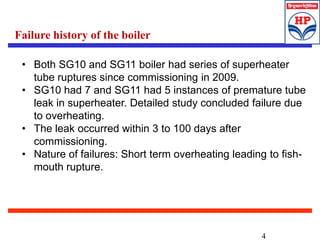
- 4. 4 • Both SG10 and SG11 boiler had series of superheater tube ruptures since commissioning in 2009. • SG10 had 7 and SG11 had 5 instances of premature tube leak in superheater. Detailed study concluded failure due to overheating. • The leak occurred within 3 to 100 days after commissioning. • Nature of failures: Short term overheating leading to fish- mouth rupture. Failure history of the boiler
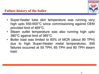
- 5. 5 • Super-heater tube skin temperature was running very high upto 550-600°C since commissioning against OEM provided limit of 469°C. • Steam outlet temperature was also running high upto 380°C against limit of 365°C. • Boiler load was limited to 60% of MCR (about 80 TPH) due to high Super-Heater metal temperatures. Still failures occurred at 50 TPH, 65 TPH and 80 TPH steam load. Failure history of the boiler
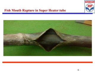
- 6. 6 Fish Mouth Rapture in Super Heater tube
- 7. 7 Metallographic Analysis • Substantial amount of black thick oxide layer in laminated formation. • No steam side deposits were observed. • 300-500 micron of magnetite layer was observed. • Microstructure analysis suggested long term temperature exposure to more than 727 °C. • Burner operating philosophy and other operational measures had no impact on failure reduction Root Cause Failure Analysis
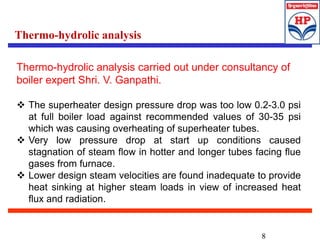
- 8. 8 Thermo-hydrolic analysis carried out under consultancy of boiler expert Shri. V. Ganpathi. The superheater design pressure drop was too low 0.2-3.0 psi at full boiler load against recommended values of 30-35 psi which was causing overheating of superheater tubes. Very low pressure drop at start up conditions caused stagnation of steam flow in hotter and longer tubes facing flue gases from furnace. Lower design steam velocities are found inadequate to provide heat sinking at higher steam loads in view of increased heat flux and radiation. Thermo-hydrolic analysis
- 9. 9 Superheater was not preceded by enough screen tube rows which normally prevents superheater from hot flue gases by soaking up radiation and equalizing the flue gas flow across the superheater cavity. Due to location of the superheater and single pass design, the superheater tubes were exposed to high radiant heat particularly at higher loads. Compromised design of superheater, lead to failures at lower as well as higher loads. Thermo-hydrolic analysis
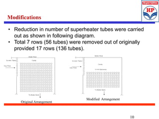
- 10. 10 • Reduction in number of superheater tubes were carried out as shown in following diagram. • Total 7 rows (56 tubes) were removed out of originally provided 17 rows (136 tubes). Modifications Original Arrangement Modified Arrangement
- 11. 11 • Super heater design was changed from single stage to double stage and attemperator has been attached intermediate header to control the steam temperature in desired limits. • Super heater metallurgy was T11 & this was upgraded to T22. Design Modifications
- 13. 13 Improved performance & reliability post-modifications Parameters Before modification After modification Remarks Load Avg 75.00 75.00 Stack Temp (Avg) 188.00 164.19 -23.81 degC O2 (%) (Avg) 6.00 3.50 -2.5% Air flow TPH (Avg) 113.00 96.58 Efficiency (Avg) 90.43 91.51 +1.1% TST (Avg) 494.00 445.00 -50 degC SH outlet temp (Avg) 384.73 355.70 SH pressure drop (Avg) 1.63 2.37 Failure frequency due to overheating 3 to 100 days NIL
- 14. 14 Major changes in Original Design Parameters Original design Modified design Number of superheater tubes per pass 136 80 MCR, TPH 140 140 Steam drum pressure, Kg/cm2g at MCR 46.4 46.4 Superheater outlet pressure, Kg/cm2g at MCR 42.9 39.6 Superheater pressure drop, Kg/cm2g at MCR 3.5 6.7 Superheater outlet temperature at MCR 380-400 335-355 Superheater steam velocity, m/s at MCR 18 32.6 Superheater steam mass flux, Kg/m2/s at MCR 289.5 492 Expected Superheater TST Max, DegC at MCR >700 490 Failure frequency due to overheating 3 to 100 days NIL
- 15. 15