4 foundation geology
•Download as PPTX, PDF•
5 likes•3,580 views

The document discusses foundations for buildings. It describes shallow foundations, which transfer loads directly to soil near the surface, and deep foundations, which transfer loads to deeper, stronger soils using piles. Shallow foundations include spread footings, which distribute loads over a large area under columns and walls, and raft/mat foundations, which use a reinforced concrete slab to spread loads across an entire building site. Deep foundations use piles that extend through weak surface soils to stronger soils below, and include precast concrete or steel piles driven into the ground or cast-in-place bored piles. The type of foundation used depends on the building loads and the bearing capacity of subsurface soils and rocks.
Report
Share


4 foundation geology
- 2. Major Building Parts Superstructure Substructure Foundation R. R. Gadgil, Dept. of Earth Science, Goa University 2
- 3. Introduction ■ “The foundation of a building is that part of walls, piers and columns in direct contact with the ground and transmitting loads to the ground.” ■ Every building needs a foundation of some kind. ■ Because of the variety of soil, rock, and water conditions that are encountered below the surface of the ground and the unique demands that buildings make upon their foundations, foundation design is a highly specialized field combining aspects of geotechnical and civil engineering. R. R. Gadgil, Dept. of Earth Science, Goa University 3
- 4. Purpose of foundation ■ To distribute the load of the structure over a large bearing area so as to bring the intensity of load within the safe bearing capacity of soil. ■ To load the bearing surface at a uniform rate to avoid differential settlement. ■ To prevent the lateral movement of supporting material. ■ To attain a level and firm bed for building operations. ■ To increase the stability of the structure as a whole. R. R. Gadgil, Dept. of Earth Science, Goa University 4
- 5. General Considerations ■ The exploratory program for the foundation of a building essentially depends on 2 factors: 1. The weight of the building and other forces acting on it and 2. The service of the building or the purpose for which it is being built. As to the service of the building, there are four categories, namely, 1. Residential buildings including housing projects 2. Commercial buildings 3. Industrial buildings 4. Pumping and power plants. Monuments and palaces do not fall into any category. R. R. Gadgil, Dept. of Earth Science, Goa University 5
- 6. Structural Loads ■ The weight of the building itself including its appurtenances is the Dead load (DL). ■ The weight of the loads applied to the building intermittently is the live load (LL). ■ For rough computations, the live load is sometimes estimated at 50% of the dead load. ■ Generally the dead and the live loads are transmitted to the foundations vertically. ■ Such is the case when all the loads are taken up by the walls and columns and then passed to the footings. ■ Roofs over large halls, such as auditoriums or mess halls are sometimes designed in the form of arches. R. R. Gadgil, Dept. of Earth Science, Goa University 6
- 7. Structural Loads ■ Besides dead and live loads, there are lateral forces acting on the building. ■ These are mainly wind and earthquake forces which act laterally and tend to push the building sideways, where they must be resisted by the shearing strength of the materials in which the foundations are built and the passive resistance of the soil mass supporting the building. ■ The resultant of vertical and lateral forces at the foundation generates two types of stresses- compressive and shear, the former causing reduction in volume of the material and consequent settlement leading to deformation, while the latter tends to slide the base of the foundation over the underlying material. ■ Other forces acting on some buildings are vibrations. ■ These are particularly evident in power and pumping plants or in industrial buildings containing large machines. R. R. Gadgil, Dept. of Earth Science, Goa University 7
- 8. Types of foundation ■ There are two basic types of foundations 1. Shallow foundation 2. Deep foundation ■ Shallow foundation – The foundation provided immediately below the lowest part of the structure near the ground level, transferring load directly to the supporting soil, is known as shallow foundation. – Shallow foundation is provided when stable soil with adequate bearing capacity occur near to the ground level. – Requirements Suitable soil bearing capacity Undisturbed soil or engineered fill R. R. Gadgil, Dept. of Earth Science, Goa University 8
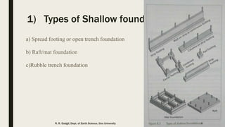
- 9. 1) Types of Shallow foundation a) Spread footing or open trench foundation b) Raft/mat foundation c)Rubble trench foundation R. R. Gadgil, Dept. of Earth Science, Goa University 9
- 10. Footing ■ Footings distribute the load to the subsoil over an area sufficient to suit the pressures to the properties of the soil or rock. ■ Their size is therefore governed by the strength of the foundation materials. ■ If the footing supports a single column it is known as a spread or pad footing whereas a footing beneath a wall is referred to as a strip or continuous footing. ■ Settlement of a footing due to a given load per unit area of its base, is a complex function of the dimensions of the base and of the compressibility, permeability and Poisson's number of the foundation materials located between the base and a depth which is at least equal to three times the width of the base.R. R. Gadgil, Dept. of Earth Science, Goa University 10
- 11. Spread footing ■ A spread footing foundation, which is typical in residential building, has a wider bottom portion than the load-bearing foundation walls it supports. This wider part "spreads" the weight of the structure over more area for greater stability. ■ The design and layout of spread footings is controlled by several factors, foremost of which is the weight (load) of the structure it will support. ■ These foundations are common in residential construction that includes a basement, and in many commercial structures. But for high rise buildings they are not sufficient. R. R. Gadgil, Dept. of Earth Science, Goa University 11
- 12. Spread footing in stone masonry R. R. Gadgil, Dept. of Earth Science, Goa University 12
- 13. Isolated Spread footing R. R. Gadgil, Dept. of Earth Science, Goa University 13
- 14. Spread footing ■ There are 3 basic types of spread footings 1. Individual footings: Generally supporting a column (either an outside wall column or an interior column) 2. Continuous or wall footings 3. The mat or raft foundations R. R. Gadgil, Dept. of Earth Science, Goa University 14
- 15. Spread footing ■ Individual footings may be an one of 3 varieties 1. Shallow slab type 2. Battered type 3. Stepped type R. R. Gadgil, Dept. of Earth Science, Goa University 15
- 16. Continuous footing ■ It is merely a wall with a widened base resting on the subsurface material. ■ This type is used preferably for light buildings such as residences, one-story school buildings or small, one-story warehouses. R. R. Gadgil, Dept. of Earth Science, Goa University 16
- 17. Continuous footing R. R. Gadgil, Dept. of Earth Science, Goa University 17
- 18. Isolated stepped type footing R. R. Gadgil, Dept. of Earth Science, Goa University 18
- 19. Raft/mat/slab foundation ■ Raft foundation is a thick concrete slab reinforced with steel which covers the entire contact area of the structure like a thick floor. ■ The reinforcing bars runs normal to each other in both top and bottom layers of steel reinforcement. ■ Sometimes inverted main beams and secondary beams are used to carry column loads that require thicker foundation slab considering economy of the structure. ■ Used generally for higher loads and prevention of excessive settlements. R. R. Gadgil, Dept. of Earth Science, Goa University 19
- 20. Raft foundation R. R. Gadgil, Dept. of Earth Science, Goa University 20
- 21. Raft/mat/slab foundation ■ The chief function of a raft is to spread the building load over as great an area of ground as possible and thus reduce the bearing pressure to a minimum. ■ In addition a raft provides a degree of rigidity which reduces differential movements in the superstructure. ■ The settlement of a raft foundation does not depend on the weight of the building which is supported by the raft. ■ It depends only on the difference between this weight and the weight of the soil which is removed prior to the construction of the raft. ■ A raft can be built at a sufficient depth so that the weight of soil removed equals the weight of the building. ■ Hence such rafts are sometimes called floating or semi-floating foundations. ■ The success of this type of foundation structure in overcoming difficult soil conditions has led to the use of deep raft and rigid frame basements for a number of high buildings on clay. R. R. Gadgil, Dept. of Earth Science, Goa University 21
- 22. ---Raft Foundation Construction Method – YouTube ---Construction of Mat Footing R. R. Gadgil, Dept. of Earth Science, Goa University 22
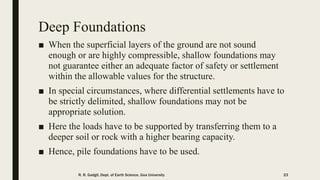
- 23. Deep Foundations ■ When the superficial layers of the ground are not sound enough or are highly compressible, shallow foundations may not guarantee either an adequate factor of safety or settlement within the allowable values for the structure. ■ In special circumstances, where differential settlements have to be strictly delimited, shallow foundations may not be appropriate solution. ■ Here the loads have to be supported by transferring them to a deeper soil or rock with a higher bearing capacity. ■ Hence, pile foundations have to be used. R. R. Gadgil, Dept. of Earth Science, Goa University 23
- 24. Deep Foundations - Purpose transfer building loads deep into the earth Basic types – Drilled (& poured) – Driven R. R. Gadgil, Dept. of Earth Science, Goa University 24
- 25. R. R. Gadgil, Dept. of Earth Science, Goa University 25
- 26. Piles ■ A pile is basically a structural foundation component where length is its maximum dimension. ■ A deep foundation is normally considered to be a pile when its total length is equal to or greater than eight times its width or minimum dimension. ■ They can be classified into 2 basic groups 1. Precast driven piles 2. Cast-in-situ bored piles R. R. Gadgil, Dept. of Earth Science, Goa University 26
- 27. Piles R. R. Gadgil, Dept. of Earth Science, Goa University 27
- 28. Precast Piles & Bored Piles ■ These are straight pieces of timber, reinforced concrete or steel which are driven into the ground by blows or vibrations until they reach the required depth. ■ They are also known as displacement piles, because of this method of installation, since when they are driven into the ground they displace the soil occupying that place. ■ Bored piles are sunk by boring holes of the required depth and diameter. ■ A steel cage of reinforcement is installed as required and then the hole is filled with concrete. ■ As a volume of soil has to be excavated and removed to construct the piles they are also known as substitution piles. R. R. Gadgil, Dept. of Earth Science, Goa University 28
- 29. Precast Concrete Plies R. R. Gadgil, Dept. of Earth Science, Goa University 29
- 30. Single Piles A column is not normally supported by a single pile, and in fact this system should not be used except in the case of a large-diameter column with a high bearing capacity. R. R. Gadgil, Dept. of Earth Science, Goa University 30
- 31. Column or End-bearing pile In this type of pile all or most of the load received at the top is transmitted integrally to the tip, with only a small part of the load transmitted by shaft (along its sides). An example of this would be a pile driven into very soft soil with the tip resting on very hard, competent ground. R. R. Gadgil, Dept. of Earth Science, Goa University 31
- 32. Friction pile On the other hand, in this type of pile, most of the load is transmitted to the ground through the skin friction of the shaft. In this case, the load reaching the tip may be smaller than that transmitted along the length of the pile shaft. Normal situations fall somewhere between the two….. R. R. Gadgil, Dept. of Earth Science, Goa University 32
- 33. Caissons or Piers A drilled-in pier or caisson is a variation of individual footing. Such piers vary in diameter from 6” to 6’ and more, the most common sizes being 24 and 36”. The hole for the pier is usually drilled with special machines and after the excavation is made, the hole is filled with concrete and sometimes reinforced with vertical steel bars. R. R. Gadgil, Dept. of Earth Science, Goa University 33
- 34. Caissons or Piers If it is necessary to spread the load carried by the pier over wider area then the actual drilled diameter of the pier, the bottom of the hole is “underrimmed” or “belled” i.e. the lower end is enlarged into a cone or bell-like design. R. R. Gadgil, Dept. of Earth Science, Goa University 34
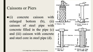
- 35. Caissons or Piers (i) concrete caisson with enlarged bottom (b), (ii) caisson of steel pipe with concrete filled in the pipe (c) and (iii) caisson with concrete and steel core in steel pipe (d). R. R. Gadgil, Dept. of Earth Science, Goa University 35
- 36. Concrete piles Concrete piles may be precast or cast-in-place. Precast piles are generally octagonal or square in cross section and are reinforced with steel bars. For cast-in-place piles, a thin steel shell with a steel core inside is driven into the ground, after which the steel core is removed and the shell is filled with concrete. R. R. Gadgil, Dept. of Earth Science, Goa University 36
- 37. Steel piles They are of 2 types: Concrete filled steel pipes (tubes) and steel H piles. Open end heavy steel tubes upto 30 in. in diameter are driven through soft deposits to rock, the material inside the tube is washed out with water or compressed air jet, then the tube is redriven to final position and filled with concrete. The H piles, have all 3 components of the letter H equal. These piles, like the steel tubes, are used to carry the weight of the building to deeper, more reliable strata. R. R. Gadgil, Dept. of Earth Science, Goa University 37
- 38. Pile Foundations R. R. Gadgil, Dept. of Earth Science, Goa University 38
- 39. R. R. Gadgil, Dept. of Earth Science, Goa University 39
- 40. Site Cast Concrete Piles Cased Piles Uncased Piles R. R. Gadgil, Dept. of Earth Science, Goa University 40
- 41. Negative Friction (drag) When a fill or load is placed on compressible soil deposit, consolidation of the compressible material takes place, earthquake liquefaction or groundwater extraction. The downward movement of soil develops skin friction between the pile and the surrounding soil and it is termed as negative skin friction. Negative skin friction can be developed from lowering on water level in compressible soils such as clay, peat, mud and soft soil and also due to increase in stress by some means (e.g. filling). R. R. Gadgil, Dept. of Earth Science, Goa University 41
Editor's Notes
- Principles of Engineering Geology and Geotechnics by Krynine and Judd pg464
- Principles of Engineering Geology and Geotechnics by Krynine and Judd pg464
- Principles of Engineering Geology and Geotechnics by Krynine and Judd pg465
- Picture from Geological Engineering
- Engineering Geology and Geotechnics by Bell pg241 When a material is compressed in one direction, it usually tends to expand in other two directions perpendicular to the direction of compression. This phenomena is called Poisson’s effect. Poisson’s ratio is a measure of this effect.
- Principles of Engineering Geology and Geotechnics by Krynine and Judd pg466
- Principles of Engineering Geology and Geotechnics by Krynine and Judd pg466
- Principles of Engineering Geology and Geotechnics by Krynine and Judd pg466
- Principles of Engineering Geology and Geotechnics by Krynine and Judd pg466
- Internet
- Internet
- Engineering Geology and Geotechnics by Bell pg242
- Engineering Geology and Geotechnics by Bell pg242
- Geological Engineering pg385
- Geological Engineering pg385
- Internet
- Geological Engineering pg386
- Geological Engineering pg387
- Geological Engineering pg387
- Principles of Engineering Geology and Geotechnics pg468-69
- Principles of Engineering Geology and Geotechnics pg468-69
- Geological Engineering pg387
- Principles of Engineering Geology and Geotechnics pg470
- Principles of Engineering Geology and Geotechnics pg471
- http://theconstructor.org/geotechnical/negative-skin-friction-on-piles/3376/ Picture from Practical Engineering Geology by Steve Hencher pg250