


802.11 mgt-opern
- 2. Management Architecture Scanning Authentication Association Power Conservation Timer Synchronization Spectrum Management Topics to be discussed
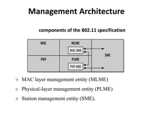
- 3. Management Architecture MAC layer management entity (MLME) Physical-layer management entity (PLME) Station management entity (SME). components of the 802.11 specification
- 4. Management Architecture What is SME ? MAC and PHY layers have acess to their corresponding MIB (Management Information Base) What is MIB ? Three interfaces: 2 by SME and one between MLME and PLME
- 5. Scanning What is scanning ? Following are the parameters used in scanning 1. BSSType (independent, infrastructure, or both) 2. BSSID (individual or broadcast) 3. SSID ("network name") 4. ScanType (active or passive) 5. ChannelList
- 6. Scanning ProbeDelay MinChannelTime and MaxChannelTime
- 7. What is passive scanning ? How is it performed ? Passive Scanning Passive scanning
- 9. Scanning Active scanning uses 3 steps: 1. Move to the channel and wait for either an indication of an incoming frame or for the ProbeDelay timer to expire. 2. Gain access to the medium using the basic DCF access procedure and send a Probe Request frame. Active Scanning
- 10. Scanning Uses 3 steps: 3. Wait for the minimum channel time, MinChannelTime, to elapse. Active Scanning
- 11. Scanning • One station in IBSS is responsible for responding to Probe Requests. • In infrastructure networks, the access points are responsible for responding to Probe Requests. • In IBSSs a station that transmits Probe Response frames may vary • A broadcast Probe Request results in a response from every access point within range. Active Scanning
- 13. Scanning Active Scanning • The second Probe Response is subject to the rules of the distributed coordination function • The first response is transmitted before the minimum response time elapses, so the station waits until the maximum response time has elapsed NOTE
- 14. Scanning Scan Report • The report lists all the BSSs that the scan discovered and their parameters. • In addition to the BSSID, SSID, and BSSType, the parameters also include: 1. Beacon interval (integer) 2. DTIM period (integer) 3. Timing parameters 4. PHY parameters, CF parameters, and IBSS parameters 5. BSSBasicRateSet
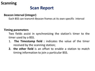
- 15. Scanning Scan Report Beacon interval (integer) Each BSS can transmit Beacon frames at its own specific interval Timing parameters Two fields assist in synchronizing the station's timer to the timer used by a BSS. 1. The Timestamp field : indicates the value of the timer received by the scanning station; 2. the other field is an offset to enable a station to match timing information to join a particular BSS.
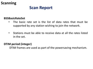
- 16. Scanning Scan Report BSSBasicRateSet • The basic rate set is the list of data rates that must be supported by any station wishing to join the network. • Stations must be able to receive data at all the rates listed in the set. DTIM period (integer) DTIM frames are used as part of the powersaving mechanism.
- 17. Scanning Joining • Joining is a precursor to association • Choosing which BSS to join is an implementation-specific decision • Common criteria used in the decision are power level and signal strength. • involves matching local parameters to the parameters required by the selected BSS • The station must also match the PHY parameters
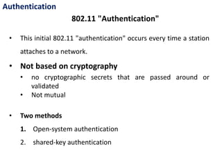
- 18. Authentication • This initial 802.11 "authentication" occurs every time a station attaches to a network. • Not based on cryptography • no cryptographic secrets that are passed around or validated • Not mutual • Two methods 1. Open-system authentication 2. shared-key authentication 802.11 "Authentication"
- 19. Authentication • An open-system authentication exchange consists of two frames 802.11 “Authentication”- Open-system authentication
- 20. Authentication • Makes use of WEP • A shared key be distributed to stations before attempting authentication. 802.11 “Authentication”- shared-key authentication
- 21. Authentication • Since the exclusive-OR is a reversible operation , with any two items, recovering the third is easy. Defeating shared-key authentication
- 22. • Low-level 802.11 authentication . • Used to speed up association transfer • Occurs before 802.1X authentication . • The sequence : • 802.11 Preauthentication . • Association • 802.1X authentication . 802.11 Preauthentication
- 23. • Need not take place immediately before association. • Stations can preauthenticate with several access points during the scanning process • As a result of preauthentication, stations can reassociate with access points immediately upon moving into their coverage area • 802.11 Preauthentication
- 24. 802.11 Preauthentication Preauthentication is not used in first case, mobile station uses Preauthentication in the second case Figure 8-7. Time savings of preauthentication
- 25. 802.11 Preauthentication Step Action without preauthentication: Figure 8-7 (a) Action with preauthentication: Figure 8- 7 (b) 0 Station is associated with AP1 Station is associated with AP1 1 Station moves right into the overlap between BSS1 and BSS2 Station moves right into the overlap between BSS1 and BSS2 and detects the presence of AP2 1.5 Station preauthenticates to AP2 2 AP2's signal is stronger, so station decides to move association to AP2 AP2's signal is stronger, so station decides to move association to AP2 3 Station authenticates to AP2 Station begins using the network 4 Station reassociates with AP2 5 Station begins using the network
- 26. 802.11i Preauthentication and Key Caching • 802.1X authentication is the most time-consuming step . • 802.11i Preauthentication, allows a station to establish a security context with a new AP before associating to it. • Preauthentication decouples the association and security procedures
- 27. 802.11i Preauthentication and Key Caching 802.11i preauthentication
- 28. 802.11i Preauthentication and Key Caching 1. The station associates to the first access point it finds on the network. It selects this AP based on the criteria in its firmware. 2. Once associated, the station can perform an 802.1X authentication. 3. Dynamic keys for the radio link are derived on both sides through the four- way handshake for pairwise keys and the group key handshake for the group keys. 4. With keys configured, the station can send and receive network protocol packets.
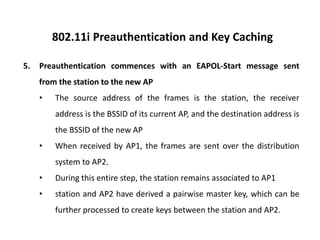
- 29. 802.11i Preauthentication and Key Caching 5. Preauthentication commences with an EAPOL-Start message sent from the station to the new AP • The source address of the frames is the station, the receiver address is the BSSID of its current AP, and the destination address is the BSSID of the new AP • When received by AP1, the frames are sent over the distribution system to AP2. • During this entire step, the station remains associated to AP1 • station and AP2 have derived a pairwise master key, which can be further processed to create keys between the station and AP2.
- 30. 802.11i Preauthentication and Key Caching 6. When the station is moved to AP2, as part of the initial association, the station includes a copy of its key cache to tell AP2 that it was already authenticated 6. AP2 receives the authentication request and searches its key cache. Finding an entry, it starts the fourway pairwise key handshake immediately.
- 31. Association • Association is a recordkeeping procedure that allows the distribution system to track the location of each mobile station • After association completes, an access point must register the mobile station on the network • Association is restricted to infrastructure networks
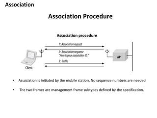
- 32. Association Association Procedure • Association is initiated by the mobile station. No sequence numbers are needed • The two frames are management frame subtypes defined by the specification. Association procedure
- 33. Association Association Procedure 1. Once a mobile station has authenticated to an access point, it can issue an Association Request frame. Stations that have not yet authenticated receive a Deauthentication frame from the access point in response. 2. The access point then processes the association request • When the association request is granted, the access point responds with a status code of 0 (successful) and the Association ID (AID). • Unsuccessful association requests include only a status code, and the procedure ends 3. The access point begins processing frames for the mobile station
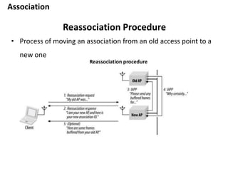
- 34. Association Reassociation Procedure • Process of moving an association from an old access point to a new one Reassociation procedure
- 35. Association Reassociation Procedure 1. The mobile station issues a Reassociation Request to the new access point. • Reassociation Request frames contain a field with the address of the old access point. • The new access point must communicate with the old access point to determine that a previous association did exist
- 36. Association Reassociation Procedure 2. The access point processes the Reassociation Request. • If the Reassociation Request is granted, the access point responds with a Status Code of 0 (successful) and the AID. • Unsuccessful Reassociation Requests include just a Status Code, and the procedure ends. 3. The new access point contacts the old access point to finish the reassociation procedure
- 37. Association Reassociation Procedure 4. The old access point sends any buffered frames for the mobile station to the new access point. • Any frames buffered at the old access point are transferred to the new access point so they can be delivered to the mobile station. • The old access point terminates its association with the mobile station.
- 38. Association Reassociation Procedure 4. The new access point begins processing frames for the mobile station Reassociation is also used to rejoin a network if the station leaves the coverage area and returns later to the same access point
- 39. Power Conservation • Many wireless applications require long battery life without sacrificing network connectivity. • Powering down the transceiver can lead to great power savings in wireless networks. • When the transceiver is off, it is said to be sleeping, dozing, or in power saving mode (PS). When the transceiver is on, it is said to be awake, active, or simply on
- 40. Power Conservation • Access points to play a key role in power management on infrastructure networks. • They are an ideal location to buffer traffic • A mobile station can communicate its power management state to its access point • Access points must remain active at all times Power Management in Infrastructure Networks
- 41. Power Conservation • Access points have two power management-related tasks 1. Buffering and delivered frames to the stations 2. Announce periodically which stations have frames waiting for them. • Listening to the buffer status requires far less power Power Management in Infrastructure Networks
- 42. Power Conservation • Part of the association request is the Listen Interval parameter, the number of Beacon periods for which the mobile station may choose to sleep. • Longer listen intervals require more buffer space on the access point; • The Listen Interval is a contract with the access point • If a mobile station fails to check for waiting frames after each listen interval, they may be discarded without notification. Power Management in Infrastructure Networks
- 43. Power Conservation • Each AID is logically connected to frames buffered for the mobile station that is assigned that AID. • Multicast and broadcast frames are buffered and linked to an AID of zero • To inform stations that frames are buffered, access points periodically transmits a traffic indication map (TIM). • Each bit in the TIM corresponds to a particular AID; Unicast frame buffering and delivery using the Traffic Indication Map (TIM)
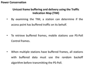
- 44. Power Conservation • By examining the TIM, a station can determine if the access point has buffered traffic on its behalf. • To retrieve buffered frames, mobile stations use PS-Poll Control frames. • When multiple stations have buffered frames, all stations with buffered data must use the random backoff algorithm before transmitting the PS-Poll. Unicast frame buffering and delivery using the Traffic Indication Map (TIM)
- 45. Power Conservation Unicast frame buffering and delivery using the Traffic Indication Map (TIM) • Each PS-Poll frame is used to retrieve one buffered frame. • That frame must be positively acknowledged before it is removed from the buffer
- 46. Power Conservation Unicast frame buffering and delivery using the Traffic Indication Map (TIM) • After transmitting the PS-Poll, a mobile station must remain awake until either the polling transaction has concluded or the bit corresponding to its AID is no longer set in the TIM. Buffered frame retrieval process
- 47. Power Conservation Delivering multicast and broadcast frames: the Delivery TIM (DTIM • 802.11 incorporates a mechanism for buffering and delivering broadcast and multicast frames. • Buffered broadcast and multicast frames are saved using AID 0.(first bit in the TIM) • Each BSS has a parameter called the DTIM Period. • At a fixed number of Beacon intervals, a special type of TIM, a Delivery Traffic Indication Map (DTIM), is sent • Buffered broadcast and multicast traffic is transmitted after a DTIM Beacon
- 48. Power Conservation Delivering multicast and broadcast frames: the Delivery TIM (DTIM • Access points must retain frames long enough for mobile stations to pick them up. • 802.11 mandates that access points use an aging function to determine when buffered frames are old enough to be discarded. • The standard forbids the aging function from discarding frames before the listen interval has elapsed
- 49. Power Conservation Delivering multicast and broadcast frames: the Delivery TIM (DTIM • Multiple buffered frames are transmitted in sequence; • Normal channel acquisition rules apply to the transmission of buffered frames • The access point may choose to defer the processing of incoming PS-Poll frames until the frames in the broadcast and multicast transmission buffers have been transmitted.
- 50. Power Conservation Delivering multicast and broadcast frames: the Delivery TIM (DTIM • In the figure , the DTIM interval of the access point is set to 3. Station 1 is operating in a sleep mode with a listen interval of 3. After a DTIM frame is transmitted, the buffered broadcast and multicast frames are transmitted, followed by any PS-Poll exchanges with associated stations.
- 51. Power Conservation Delivering multicast and broadcast frames: the Delivery TIM (DTIM • At the second beacon interval, only broadcast and multicast frames are present in the buffer, and they are transmitted to the BSS. • At the fifth beacon interval, a frame has also been buffered for station 1. • It can monitor the map in the DTIM and send a PS-Poll after the transmission of buffered broadcast and multicast frames has concluded
- 52. Power Conservation IBSS Power Management • Power management in an IBSS is not efficient since there is no logical central coordinator. So burden is placed on the sender • Power management is based on traffic indication messages • Stations use announcement traffic indication messages (ATIMs), to preempt other stations from sleeping • All stations in an IBSS listen for ATIM frames • Stations that do not receive ATIM frames are free to conserve power • In effect, the ATIM frame is a message to keep the transceiver on.
- 53. Power Conservation IBSS Power Management ATIM usage A multicast ATIM frame can be used to notify an entire group of stations to avoid entering low-power modes.
- 54. Power Conservation IBSS Power Management • A time window called the ATIM window follows the Beacon transmission • All nodes must remain active during this period • It starts at the time when the beacon is expected and ends after a period specified when the IBSS is created. ATIM window
- 55. Power Conservation IBSS Power Management • If the beacon is delayed due to a traffic overrun, the usable portion of the ATIM window shrinks by the same amount. • In the fig. , The ATIM window remains constant, starting at the target beacon interval and extending the length of the ATIM window. • The usable period of the ATIM window shrinks by the length of the delay in beacon transmission
- 56. Power Conservation IBSS Power Management • To monitor the entire ATIM window, stations must wake up before the target beacon transmission. • Four situations are possible: • the station has transmitted an ATIM, • received an ATIM, • neither transmitted nor received, • or both transmitted and received.
- 57. Power Conservation IBSS Power Management • Stations to which ATIM frames are addressed must also avoid sleeping • A station is permitted to sleep only if it neither transmits nor receives an ATIM. • When a station stays up due to ATIM traffic, it remains active until the conclusion of the next ATIM window
- 58. Power Conservation IBSS Power Management • Only certain control and management frames can be transmitted during the ATIM window: • Beacons, RTS, CTS, ACK, and, of course, ATIM frames • Transmission takes place according to the rules of the DCF. • Acknowledgments are required for uncast ATIM frames, but not for multicast ATIM frames. • Buffered broadcast and multicast frames are transmitted after the conclusion of the ATIM window, subject to DCF constraints
- 59. Power Conservation IBSS Power Management • Following the transmission of broadcast and multicast frames, a station may attempt to transmit unicast frames that were announced with an ATIM. • Following all transmissions announced with an ATIM, stations may transmit unbuffered frames to other stations that are known to be active • If contention is severe, the station must reannounce the transmission with an ATIM at the start of the next ATIM window.
- 60. Power Conservation IBSS Power Management • Figure illustrates several of these rules Effect of ATIM on powersaving modes in an IBSS network
- 61. Timer Synchronization • Especially important in frequency-hopping networks • Each station in a BSS maintains a copy of the Timing Synchronization Function (TSF), In addition to local station timing • TSF a local timer synchronized with the TSF of every other station in BSS • TSF is based on a 1-MHz clock and "ticks" in microseconds • Beacon frames are used to periodically announce the value of the TSF to other stations
- 62. Timer Synchronization • Access points are responsible for maintaining the TSF time • Stations associated with an AP must simply accept the AP’s TSF as valid. • Access points copy their timer is copied into the Beacon's timestamp field • Stations may add a small offset to the received timing value to account for local processing • Associated stations maintain local TSF timers so they can miss a Beacon frame and still remain roughly synchronized with the global TSF Infrastructure Timing Synchronization
- 63. Timer Synchronization • To assist active scanning stations in matching parameters with the BSS, timing values are also distributed in Probe Response frames Infrastructure Timing Synchronization To match the local timer to the network timer, a adds the number of microseconds since it was received.
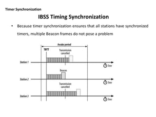
- 64. Timer Synchronization • All stations in the IBSS prepare to transmit a Beacon frame at the target time. • As it approaches, all other traffic is suspended. • All stations in the IBSS generate a backoff timer for Beacon transmission; • the backoff timer is a random delay between zero and twice the minimum contention window for the medium. • After the target beacon interval, all stations begin to count the Beacon backoff timer down to zero. • If a Beacon is received before the station's transmission time, the pending Beacon transmission is canceled IBSS Timing Synchronization
- 65. Timer Synchronization • Because timer synchronization ensures that all stations have synchronized timers, multiple Beacon frames do not pose a problem IBSS Timing Synchronization
- 66. Timer Synchronization • Rules for adopting the received timestamp are more complex in an independent network. • No centralized timer exists, so the goal of the standard is to synchronize all timers to the timer of the fastest-running clock in the BSS. • When a Beacon is received, the timestamp is adjusted for processing delays and compared to the local TSF. IBSS Timing Synchronization
- 67. • Spectrum management are designed to allow the wireless network to react to conditions and change radio settings dynamically. • Two services were defined in 802.11h to help meet regulatory requirements. 1. Transmit Power Control (TPC) • can dynamically adjust the transmission power of a station. 2. Dynamic Frequency Selection (DFS) • developed mainly to avoid interfering with some 5 GHz systems. Spectrum Management
- 68. Transmit Power Control (TPC) • Controlling transmission power brings many benefits 1. High power decreases battery life 2. Extra reach represents "wasted" power 3. Interference & Reduction in network throughput Spectrum Management High client power interference with multiple APs problems caused by high client power
- 69. Transmit Power Control (TPC) • The difference between the two circles is the excess range caused by transmitting too high • Running the radio transmitter higher than necessary will drain the battery • The shaded area represents the area which is blocked because Client #1 is transmitting at power that is too high. • Controlling the range of transmission also makes the network function more smoothly Spectrum Management
- 70. Basic operation of transmit power control • The Country element specifies the regulatory maximum power, and the Power Constraint element can be used to specify a lower maximum transmission power specific to the network • Stations must calculate the maximum transmission power that may be used. • Typically, this is calculated by taking the regulatory maximum power and subtracting any constraints for mitigation or additional local constraints Spectrum Management
- 71. Changes to the association process • A station must supply the minimum and maximum transmission power in a Power Capability information element during association • Access points may also reject Stations • that have high power • with low transmit power • Low transmit power capability may increase the possibility of hidden nodes Spectrum Management
- 72. Changing the transmission power • Transmission power may be dynamically adjust on a frame-by-frame basis - For each frame, the receiver may compute the link margin, - link margin - amount by which the received power exceeds the minimum acceptable value - Most stations aim for a small link margin - specific calculation of link margin and the determination of a particular desired value are not specified by the standard. Spectrum Management
- 73. Changing the transmission power • To change transmission power, Stations send an Action frame requesting a transmission report. • Action frame sent in response contains a TPC Report element with two descriptive statistics 1. Transmit power of the report frame. 2. A value for the link margin • The receiver estimate the path loss , Based on the transmission power • the link margin informs the receiver of the ratio between the received power and the minimum acceptable power Spectrum Management
- 74. Changing the transmission power • If the link margin is "too high," transmit power can be reduced. If the link margin is "too low," the transmit power can be increased. • Spectrum Management