


Alternating Current Machines-Synchronous Machines
- 1. NUE046: Alternating Current Machines - Synchronous Machines section
- 2. Classroom Rules : I talk, you listen I don’t allow: Heads on desk Feet on desk Going to sleep in class MP3 players Mobile phones are to be off, or on “silent” unless OK’d with me, and in you bag (not on desk) Should they be OK’d, and you receive a call, you will answer it outside the classroom No SMS-ing in class Keith Butler’s number is: 0417 637 909
- 3. Topics (from Learning Outcomes) 10. Three-phase synchronous machines • operating principles • construction feature • application 11. Three-phase synchronous machines • effects of load changes • effects of excitation change • load/current characteristics 12. Single phase synchronous machines • alternators • motors • applications
- 4. Assessment All prac’s must be completed A final written exam will be given on the learning outcomes covered. Should a student fail, they will be allowed one further attempt during block. Should they fail this they will be allowed one further attempt within six weeks of completing the block. Should they fail this they will be in a “Show Cause” situation.
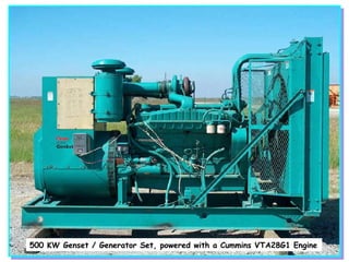
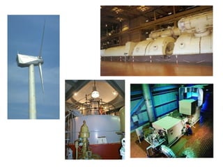
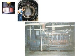
- 6. 500 KW Genset / Generator Set, powered with a Cummins VTA28G1 Engine
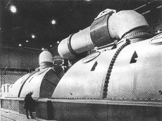
- 9. 2 x 14MW Synchronous Motors … apparently, they use permanent magnets!
- 11. 3 phase Dunlite machine
- 13. Synchronous machines are not just the big units, but they can be small also.
- 14. R, L, and C on AC Revision of...
- 15. Resistance on AC Current is in phase with voltage. Time-> V AC Supply R V I I
- 16. Inductance on AC L AC supply Current lags the Voltage by 90 o V I V I
- 17. Capacitance on AC But if an ammeter were placed in series it would most definitely read a current. Current appears to pass through the capacitor. In reality, it is charging in one direction, and then discharging and recharging in the other direction. C AC Supply
- 18. Capacitance on AC V Current leads the Voltage by 90 o I C AC Supply V I
- 19. Inductive and Capacitive Reactance This opposition to current flow is called: Inductive reactance, in inductors. (X L ) Capacitive reactance in capacitors. (X C ) Both Inductors and Capacitors oppose, or “resist” current flow when connected to AC supplies. While it opposes current flow, it is NOT called resistance. Current flow through resistance produces HEAT. Current flow in inductors and capacitors doesn’t!
- 20. Star and Delta Connections Revision of...
- 21. Star Generator / Transformer / Motor A C B S F S F S F S F S F S F B A C
- 22. A C B Motor Star Why isn’t a neutral run to a balanced three phase Star connected load? A B C N ?????
- 23. A C B Motor Star Because the Star point is at 0V A B C And the neutral is at zero volts also. So if they were joined no current would flow. So why join it? 0V 0V N 0A
- 24. A C B Motor Star A B C The neutral is not connected to a balanced three phase star connected load. Only connected to unbalanced loads!!!
- 25. Transformer Delta Generator / Transformer / Motor S F B S F C A B C F S F S F S S F A
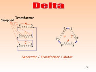
- 26. Transformer Delta Generator / Transformer / Motor S F B S F C A B C S F S F S F S F A Swapped
- 27. 3-phase Transformer Secondary Delta S F B C S F A S F Note that all windings are connected in series, with the two ends joined together. A B C
- 28. Delta If we did that with three batteries, there would be major problems!
- 29. Delta The voltmeter should read the sum of the three voltages? Right? Transformer The voltmeter reads the phasor sum of the voltages. V A V B V C A C B F S F S F S V
- 30. Delta The voltmeter reads, in effect, the distance between the beginning of V A and the end of V C . ie. 0V We can connect the two ends together because the phasor sum adds up to zero! V A V B V C A C B F S F S F S Transformer V
- 31. Delta Transformer No Arc! V A V B V C A C B F S F S F S The voltmeter reads, in effect, the distance between the beginning of V A and the end of V C . ie. 0V We can connect the two ends together because the phasor sum adds up to zero!
- 32. Three Phase Power Equation Revision of...
- 33. Generator Load P = 3 x V PH x I PH x Cos = 3 x V L / 3 x I L x Cos = 3/ 3 x V L x I L x Cos = 3 V L x I L x Cos P = 3 x V PH x I PH x Cos = 3 x V L x I L / 3 x Cos = 3/ 3 x V L x I L x Cos = 3 V L x I L x Cos Three Phase Power STAR V L = 3 V PH I L = I PH DELTA I L = 3 I PH V L = V PH
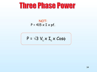
- 34. P = 3 V L x I L x Cos NOT: P = 415 x I x pf. Three Phase Power
- 35. Three Single Phase Power Equations: True Power = Watts = V x I x Cos Apparent Power = VA = V x I Reactive Power = VAR’s = V x I x Sin Power Factor = Cos where Cos = Cosine of the angle between Voltage and Current
- 36. VA Watts Var’s Phase angle between current and volts This can be put as a triangle: VA 2 = Watts 2 + Var’s 2
- 37. Alternators, where the windings are limited by the current through them , are rated in VA. To rate them in watts, (ie. watts delivered to the load) would give no idea of the current through them. Load 3 = 14.14A at 45º Load 1 = 10A Load 2 = 20A at 60º P = V x I x Cos 45º = 240 x 14.14 x 0.707 = 2.4kW P = V x I x Cos 0º = 240 x 10 x 1 = 2.4kW P = V x I x Cos 60º = 240 x 20 x 0.5 = 2.4kW V=240V
- 38. Q What dictates the phase angle of the current supplied by a single alternator supplying a single load? A The load V=240V Load 3 = 14.14A at 45º Load 1 = 10A Load 2 = 20A at 60º P = V x I x Cos 45º = 240 x 14.14 x 0.707 = 2.4kW P = V x I x Cos 0º = 240 x 10 x 1 = 2.4kW P = V x I x Cos 60º = 240 x 20 x 0.5 = 2.4kW
- 39. V Al currents here take the same power Constant power line
- 40. Al currents here take the same power Higher power V
- 41. Al currents here take the same power Constant power line V
- 42. Al currents here take the same power Lower power V
- 43. So much for revision...
- 45. Alternator - Diesel Engine - Steam Turbine - Small petrol engine Mechanical Energy Electrical Energy Losses Alternator Prime Mover Alternator: Pout Eff% = x 100 Pin Alternator: Pin = Pout + Losses
- 46. Synchronous Motor Losses Mechanical Energy MSB Electrical Energy Motor: Pout Eff% = x 100 Pin Motor Pin = Pout + Losses Motor Load
- 47. Synchronous Machine Stator - Identically wound to an induction motor. - Connected to supply. Rotor - Constant DC field - Connected to supply via sliprings. Electrical Power DC Supply
- 48. The stator produces a rotating magnetic field exactly the same as an induction motor. The rotor is a magnet and locks in to the RMF Rotor travels at SYNCHRONOUS SPEED. SYNCHRONOUS MOTOR
- 49. Synchronous Machine If a synchronous motor is OVER driven by the load (eg electric train going down a hill), then it will generate power, still at synchronous speed. If an alternator coupled to the grid is UNDER driven by the prime mover (eg steam stops), then it will motor, and drive the turbine at synchronous speed. Electrical Power DC Supply
- 50. Synchronous Machine In other words, the two machines are identical in construction. Electrical Power DC Supply
- 52. 3000RPM 1500RPM 1000RPM 750RPM Characteristic of WEG ® Induction Motors. What is the tendency as RPM gets lower? 185kw 310A, .88pf 315A, .86pf 343A, .80pf 348A, .78pf 220kw 362A, .89pf 375A, .86pf 408A, .78pf 412A, .78pf 150kw 242A, .90pf 265A, .87pf 279A, .80pf 278A, .77pf Lower the RPM, Larger value I S More lagging I S 110kw 182A, .90pf 200A, .84pf 205A, .80pf 203A, .81pf 22kw 39A, .87pf 41A, .83pf 42A, .80pf 47A, .74pf 4kw 7.8A, .87pf 8.2A, .82pf 9A, .74pf 11A, .63pf
- 53. So why use a Synchronous Motor? Uses: Low Speed Drives. Low speed induction motors draw very large currents at poor power factors. This cannot be altered or corrected. In synchronous motors, the p.f. can be altered to cause the motor to draw minimum current. (The alternative is to use a high speed induction motor through a gearbox.) Power Factor Correction Constant Speed drives
- 54. Construction
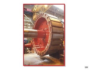
- 57. 2 basic types: Cylindrical rotor Salient Pole -Low speed -Diesel Prime Mover -Hydro systems -High speed -Steam Turbine Salient Pole Rotor Cylindrical Rotor
- 64. www.tecowestinghouse.com Small salient pole synchronous machine rotor
- 75. Synchronous Motor Losses Mechanical Energy MSB Electrical Energy Motor: Pout Eff% = x 100 Pin Motor Pin = Pout + Losses Motor Load
- 76. Stator Construction Same as an induction motor.
- 77. 2-Pole Machine ie. 3000RPM Stator Construction A1 A2
- 78. Stator Construction Stator Construction
- 79. 2-Pole Machine ie. 3000RPM In reality, the coils span more slots in a 2-pole motor. Stator Construction Notice that for a two pole stator we have a 2-pole rotor A1 A2 B1 B2 C1 C2 N S
- 80. Stator Construction N N S S A A A A B B B B C C C C 4-pole machine A four pole stator must have a four pole rotor
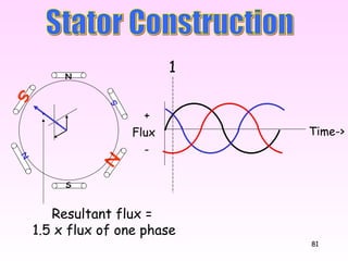
- 81. Time-> S Stator Construction N Flux + - 1 Resultant flux = 1.5 x flux of one phase N S N S
- 82. Time-> Resultant flux = 1.5 x flux of one phase Stator Construction Flux + - 2 N S N S N S
- 83. Time-> Stator Construction Flux + - 3 4 5 6
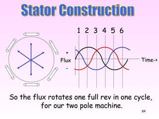
- 84. Time-> So the flux rotates one full rev in one cycle, for our two pole machine. Stator Construction Flux + - 3 4 5 6 1 2
- 85. Time-> Because the flux is a constant value, it gives: 1. Very quiet operation 2. Constant torque as the rotor rotates. Stator Construction Flux + - 3 4 5 6 1 2
- 86. Time-> This rotating magnetic field rotates at: 3000RPM for a 2-pole motor 1500RPM for a 4-pole motor Stator Construction Flux + - 3 4 5 6 1 2
- 87. Time-> To reverse the direction of rotation: reverse any two phases to the motor. Stator Construction Flux + - 3 4 5 6 1 2
- 88. where N = RPM f = frequency P = Number of poles (per phase). N = 120f/P So the speed of the rotating magnetic field is affected by: Frequency, and Number of poles. Stator Construction
- 89. As the rotating magnetic field rotates, the rotor is locked in synchronism with it and is dragged along for the ride. Stator Construction
- 90. As the rotating magnetic field rotates, the rotor is locked in synchronism with it and is dragged along for the ride. Construction N S
- 91. What will happen as a load is put on the shaft? Construction N S
- 92. What will happen as a load is put on the shaft? Construction N S
- 93. The load tries to slow it down. But it must do synchronous speed! So it stretches the lines of flux. Construction N S
- 94. Construction C/L of RMF C/L of Rotor Field Torque Angle N S
- 95. If the lines stretch to breaking point (ie too much load), then the rotor stalls This is referred to as “Pull Out Torque”. N S Construction
- 96. What would the Torque Curve look like? RPM Ns 0 Torque Curve for an induction motor Torque
- 97. What would the Torque Curve look like? Torque RPM Ns 0 Torque “Curve” for a Synchronous Motor Zero Torque below synchronous speed Pull out Torque
- 98. Starting a Synchronous Motor? 1. Amortisseur winding
- 100. Induction Motors Rotor Construction Squirrel Cage
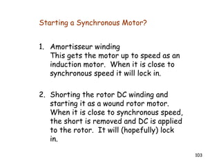
- 103. Starting a Synchronous Motor? 1. Amortisseur winding This gets the motor up to speed as an induction motor. When it is close to synchronous speed it will lock in. 2. Shorting the rotor DC winding and starting it as a wound rotor motor. When it is close to synchronous speed, the short is removed and DC is applied to the rotor. It will (hopefully) lock in.
- 104. 3. Using a pony motor to get the synchronous motor up to speed, then applying AC to the stator and DC to the rotor. (Not applicable if there is a high starting torque load connected) Note that these starting methods will only work if the load on the motor at start can be reduced or eliminated. Starting a Synchronous Motor?
- 105. • Amortisseur windings also reduce hunting. • Hunting is rhythmic fluctuations of the RPM around an average value. • If not subdued, hunting can cause the rotor to swing out of synchronism. Hunting
- 106. Revs Time Hunting
- 107. And all this while it is whizzing around at synchronous speed! Hunting N S N S N S N S N S
- 108. And all this while it is whizzing around at synchronous speed! Hunting N S
- 109. Electrical Operation
- 110. V supply V induced Phasor Diagram of Synchronous Motor Induced in the stator from the rotor
- 111. V supply V induced V R Phasor Diagram of Synchronous Motor Torque angle I supply
- 112. Phasor diagram for increased load: (Excitation current held constant) V supply V R Increased load = Increased Torque Angle Increasing the load increases the power taken from supply V induced I supply V induced
- 113. V supply Phasor diagram for increased excitation: (Constant Load) Constant load = Constant Power line V induced V induced
- 114. Phasor diagram for increased excitation: (Constant Load) V supply Constant load = Constant Power line V induced
- 115. V supply Phasor diagram for increased excitation: (Constant Load) So to force the supply current leading, we INCREASE excitation Constant load = Constant Power line V induced V R I supply
- 116. V supply Phasor diagram for decreased excitation: (Constant Load) Constant load = Constant Power line V induced I supply V R
- 117. V supply Phasor diagram for decreased excitation: (Constant Load) So to force the supply current lagging, we DECREASE excitation Constant load = Constant Power line I supply V R V induced
- 118. V supply V induced I supply V R Constant load = Constant Power line V supply V supply I supply V R V induced V induced I supply V R
- 119. V supply With a constant load, changing excitation changes the phase angle and value of supply current. I supply By increasing the DC excitation current to the rotor, the synchronous motor can act as a capacitor It can be used for power factor correction. Constant load = Constant Power line
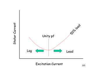
- 120. Excitation Current Stator Current 50% load Unity pf Lag Lead
- 121. Deductions From Vee Curves At any particular load there is a certain value of rotor current which gives a minimum value of stator current and unity pf. If the rotor current is altered either way, the stator current will increase, and pf will decrease away from 1. For any given load there is a certain value of rotor current below which the rotor will fall out of synchronism. For any given load there are two values of rotor current that will give identical values of stator current. The lower value gives a lagging pf, and the higher value gives a leading pf.
- 122. Excitation Current Stator Current 50% load Lag Lead 75% load Stability limit pf=1
- 123. 0.8 pf lag Unity 0.8 pf lead Per unit Power output
- 126. Points: At a set load there is a value of excitation that will give minimum line current. Reducing OR increasing excitation from this value will only increase line current. At any other value of line current, there are two values of excitation current that can produce this. If a synchronous motor is heavily loaded, supply current may not be able to be driven highly leading. If a synchronous motor is lightly loaded, supply current can be driven highly leading.
- 127. Single Phase Synchronous Motors Used when constant speed is critical, with low torque requirements. They have low efficiency, hence made in small sizes. Application: clocks record players timers recorders communications servo installations Two main types: Reluctance motor Hysteresis motor
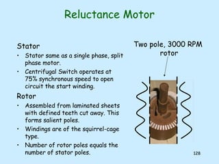
- 128. Reluctance Motor Stator Stator same as a single phase, split phase motor. Centrifugal Switch operates at 75% synchronous speed to open circuit the start winding. Rotor Assembled from laminated sheets with defined teeth cut away. This forms salient poles. Windings are of the squirrel-cage type. Number of rotor poles equals the number of stator poles. Two pole, 3000 RPM rotor
- 129. Reluctance Motor Operation Starts as an induction motor, with slip. A single phase stator has a “Start” and “Run” winding. At 75% centrifugal the centrifugal switch operates. As the load is light there is small slip The salient poles become permanently magnetised by the stator field The salient poles will then lock to the stator field. Once locked into synchronism the motor will continue to operate at synchronous speed. Not as much power output as a similar physical size 1-phase motor.
- 130. Hysteresis Motor Rotor Constructed from hardened steel rings, instead of thin, magnetically soft, silicon steel laminations. “ Hysteresis” opposes any change once the flux is created, so the rotor will lock into the RMF like a permanent magnet. Stator Often a shaded pole stator principle is used. If the shaded pole principle is used then the motor is self starting. Magnetic poles are established in the rotor. These poles lock to the stator poles. The rotor runs at synchronous speed determined by the poles and frequency.
- 131. Alternators
- 132. Why generate AC?… Why not DC? DC cant be “transformed” through a transformer. AC can go through a transformer. Large brushless DC generators are not possible Large brushless AC alternators are! Why do we want to transform it? It is easier to transmit to distant places at higher voltages as the current will be lower. (P=V x I) Induction motors are simpler and cheaper than DC motors
- 133. Voltage Generation
- 134. N S V Generating an AC Voltage
- 135. N S Generating an AC Voltage Time-> Volts + -
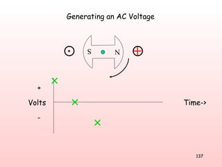
- 136. Generating an AC Voltage Time-> N S Volts + -
- 137. Generating an AC Voltage Time-> N S Volts + -
- 138. Generating an AC Voltage Time-> N S Volts + -
- 139. N S Generating an AC Voltage Time-> Volts + -
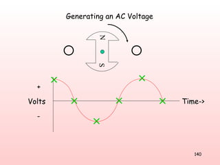
- 140. Generating an AC Voltage Time-> N S Volts + -
- 141. N S V Generating a AC Voltage 3-Phase
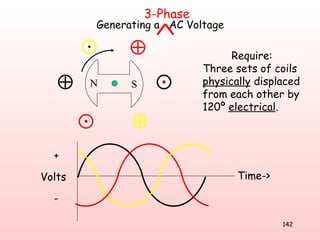
- 142. N S Time-> Require: Three sets of coils physically displaced from each other by 120º electrical . Volts + - Generating a AC Voltage 3-Phase
- 143. N S V A V C V B Generating a AC Voltage 3-Phase
- 144. A1 A2 Generating a AC Voltage 3-Phase N S
- 145. Generating a AC Voltage 3-Phase N S A1 A2 B1 B2 C1 C2
- 146. N N S S A A A A B B B B C C C C 4-pole machine A four pole stator must have a four pole rotor Generating a AC Voltage 3-Phase
- 147. Alternator Reasons for having the three phase winding on the stator rather than the rotor: More space on the stator for the three phase winding. Only one, low voltage winding on the rotor. Easier to insulate. Less problems with centrifugal force. Only two sliprings required rather than four (3-ph + N)
- 148. Alternator Stator - Connected to load . Rotor - Constant DC field - Connected to its own DC supply via sliprings. Electrical Power Mechanical Power Magnetic Field
- 149. Alternator Q: What keeps an alternator producing 50Hz under all load conditions? A: The governor on the prime mover. It detects any drop in speed, and tries to speed the unit up. Alternator Petrol Engine
- 150. Electrical Operation
- 151. I FIELD V OUT Alternator Excitation Curve (No Load)
- 152. Alternator Alt Load R X L Internal Impedance
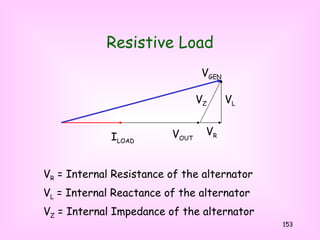
- 153. Resistive Load V OUT V Z = Internal Impedance of the alternator V R = Internal Resistance of the alternator V L = Internal Reactance of the alternator I LOAD V R V Z V L V GEN
- 154. Resistive Load Load current and p.f. are dictated by the LOAD! V OUT I LOAD V R V Z V L V GEN Notice that terminal volts DROP as load increases
- 155. Inductive Load V OUT I LOAD V R V Z V L V GEN Parallel
- 156. Inductive Load Now there is a greater voltage drop under load V OUT I LOAD V R V Z V L V GEN
- 157. Capacitive Load V OUT I LOAD Now there is a voltage RISE under load Because of the voltage rise under load, it is not desirable to run alternators at a leading power factor. V R V Z V L V GEN Parallel
- 158. Effect of Power Factor on Output Voltage Leading pf Unity pf Lagging pf Load Current Output Voltage
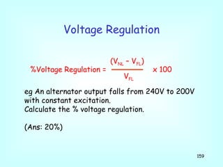
- 159. Voltage Regulation (V NL – V FL ) %Voltage Regulation = x 100 V FL eg An alternator output falls from 240V to 200V with constant excitation. Calculate the % voltage regulation. (Ans: 20%)
- 160. Summary: When an alternator is standing by itself with a single load: Output voltage is affected by excitation current Output frequency is affected by input power to the alternator. Alternators - stand alone
- 161. When an alternator is tied to the grid, you cannot change: Grid voltage Grid frequency So the output voltage of the alternator will not change, and the output frequency of the alternator will not change. Notice that, for a stand alone alternator with stand alone load, these are the two things that changed when: (a) the excitation was altered, and (b) the power input to the alternator was increased (ie. Put the foot down on the prime mover) Alternators tied to the Grid
- 162. Alternators tied to the Grid V OUT V GEN If excitation is increased , and V OUT cannot alter, V GEN will increase and push the triangle over. I LOAD 1. Altering Excitation. V R V Z V L
- 163. V OUT I LOAD V GEN If excitation is increased , and V OUT cannot alter, V GEN will increase and push the triangle over. Alternators tied to the Grid 1. Altering Excitation. Note that input power to the alternator is not changing, so output power does not change either. V R V Z V L Constant Power Line (Output power of the alternator has not Changed)
- 164. V OUT I LOAD If excitation is reduced , and V OUT cannot alter, V GEN will reduce and pull the triangle back. Alternators tied to the Grid 1. Altering Excitation. V GEN This drives the load current lagging V R V Z V L
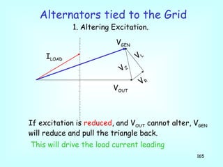
- 165. V OUT I LOAD V GEN If excitation is reduced , and V OUT cannot alter, V GEN will reduce and pull the triangle back. Alternators tied to the Grid 1. Altering Excitation. This will drive the load current leading V R V Z V L
- 166. If input power is reduced , and frequency and V OUT cannot alter, output power will reduce . Alternators tied to the Grid 2. Altering input power to the alternator. V OUT V GEN I LOAD V R V Z V L
- 167. If input power is reduced , and frequency and V OUT cannot alter, output power will reduce . Alternators tied to the Grid 2. Altering input power to the alternator. V OUT V GEN I LOAD V R V Z V L
- 168. If input power is reduced , and frequency and V OUT cannot alter, output power will reduce . Alternators tied to the Grid 2. Altering input power to the alternator. V OUT V GEN I LOAD Size of triangle reduces V R V Z V L
- 169. If input power is reduced , and frequency and V OUT cannot alter, output power will reduce . Alternators tied to the Grid 2. Altering input power to the alternator. V OUT V GEN I LOAD Size of triangle reduces V R V Z V L
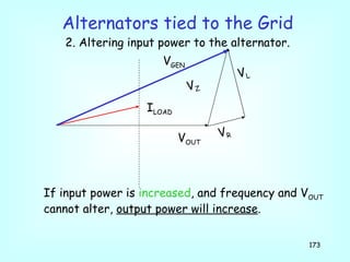
- 170. If input power is increased , and frequency and V OUT cannot alter, output power will increase . Alternators tied to the Grid 2. Altering input power to the alternator. V OUT V GEN I LOAD V R V Z V L
- 171. If input power is increased , and frequency and V OUT cannot alter, output power will increase . Alternators tied to the Grid 2. Altering input power to the alternator. V OUT V GEN I LOAD V R V Z V L
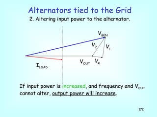
- 172. If input power is increased , and frequency and V OUT cannot alter, output power will increase . Alternators tied to the Grid 2. Altering input power to the alternator. V OUT V GEN I LOAD V R V Z V L
- 173. If input power is increased , and frequency and V OUT cannot alter, output power will increase . Alternators tied to the Grid 2. Altering input power to the alternator. V OUT V GEN I LOAD V R V Z V L
- 174. Alternators - tied to the Grid Summary : Changing excitation changes the pf of output current. Changing input power changes output power Increasing excitation drives load current lagging Reducing excitation drives load current leading Increasing input power increases output power Reducing input power reduces output power Output frequency and voltage do not change.
- 175. Alternators – stand alone Summary : Changing excitation changes output voltage . Changing input power changes RPM , which changes output frequency . Here, output frequency and voltage do change Get your head around that !
- 176. Paralleling Alternators To parallel alternators (or parallel one onto the grid), the following criteria must be met: Output voltage must be the same Output frequency must be the same Phase rotation must be the same Supply voltage must be in phase It is understood that they must both produce the same waveform – a sine wave!
- 177. Alternator Rating Alternators are rated according to: Frequency Voltage Current kVA The frequency dictates the RPM (3000, 1500, etc). Voltage and Current give the kVA rating.
- 178. Efficiency Losses: By far the main loss in an alternator is HEAT loss. If an alternator can be kept cool, more power can be obtained from it. ie. Instead of a 300MW machine, it will become a 500MW machine. More power must be put into it to get this increased output power. Cooling large alternators is a big deal! They are often cooled using hydrogen.
- 179. Efficiency Losses: • Copper Losses: I 2 R losses in the stator winding I 2 R losses in the rotor winding • Iron Losses: Hysteresis loss in stator Eddy current Loss in stator • Friction and windage
- 180. Single Phase Alternators Electrical Power Mechanical Power Regulator Stator Magnetic Field
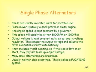
- 182. Single Phase Alternators These are usually low rated units for portable use. Prime mover is usually a small petrol or diesel engine. The engine speed is kept constant by a governor. This speed will usually be either 3000RPM or 1500RPM Output voltage is kept constant using an automatic voltage regulator. This senses the output voltage and adjusts the rotor excitation current automatically. They are usually self exciting, so if the load is left on at start, they may not build up output voltage. Many small alternators are brushless. Usually, neither side is earthed. This is called a FLOATING system.
- 184. Brushless Alternators Note: Self Excited Rotor AC is sampled Regulator DC Field P.S . 3-phase out
- 185. Brushless Alternators Rotor Regulator 3-phase out Prime Mover 3-phase out
- 186. Small Alternators -Factors when choosing: Voltage: 240V / 415V (1-phase or 3-phase) kVA rating RPM (3000RPM or 1500RPM) Petrol or Diesel Brushless or brushes Ability to start loads such as motors Extras: Soundproofing, starting, power outlets, mounting holes, 12VDC / welding output
- 187. T E N D h e