Location via proxy:   [ UP ]  
[Report a bug]   [Manage cookies]                
SlideShare a Scribd company logo
Biw fixture
Definitions
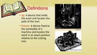
• Jig: A device that holds
the work and locates the
path of the tool.
• Fixture: A device fixed to
the worktable of a
machine and locates the
work in an exact position
relative to the cutting
tool.
Superior Jig
Flexible Fixturing Systems
Fixtures
• More of a permanent tool that is used for assembly purposes.
• Typically does not have as much flexibility as a jig.
• Most likely used for high volume production.
• Made of durable materials such as tool steel, iron, aluminum alloys,
etc.
Other Fixture Examples
• Used most commonly for welding
and metal assembly work.
• Typically used for products that
must be very precise.
• Sometimes are exposed to high
temperatures and stresses
Type of Fixtures
(a) Turning fixtures
(b) Milling fixtures
(c) Fixture for grinding
(d) Fixture for broaching
(e) Fixture for boring/drilling
(f) Tapping fixture
(g) Fixture for welding
(h) Assembling fixture
Standard Parts Co.
Fixture components
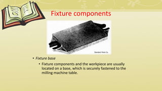
• Fixture base
• Fixture components and the workpiece are usually
located on a base, which is securely fastened to the
milling machine table.
Standard Parts Co.
Fixture components
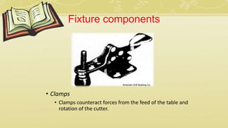
• Clamps
• Clamps counteract forces from the feed of the table and
rotation of the cutter.
American Drill Bushing Co.
Fixture components
• Set blocks
• Cutter set blocks are mounted on the fixture to
properly position the milling cutter in relation to the
workpiece.
Biw fixture
• Detailed design of locators
• Detailed design of clamps
• Detailed design of supports
• Positions of locators
• Positions of clamps
• Positions of supports, if any
• Type of locators
• Type of clamps
• Type of supports
• Clamping forces and sequence
The following outputs are included in the
fixture element design:
Fixture Design Criteria
• Design specifications
• Factory standards
• Ease of use and safety
• Economy
Body In White (BIW)
Fixtures
Example :
Fixture For Welding
Various Aspects Of Fixture Design
BIW – Weld Fixtures
 Design Process/Methodology .
 Different Types of Welding Fixture Units.
 Design Inputs.
 Design Outputs.
Design Input
 Functional and Performance Requirements.
 Car Product.
 System Layout.
 Tool Information Sheet.
 Weld Study Information.
 Miscellaneous Information.
Design Input
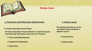
1. Functional and Performance Requirements
 Product Assembly Process Sheet
(Product Assembly Process Sheet is a sheet that gives
the following information about the Car Product)
 Parts Assembly Sequence.
 Sequence Of Operation.
 Cycle Time.
2. System Layout
The following Points are to be
considered while studying a
System Layout .
 Flow Of Parts.
 Station Pitch.
3. Car Product
The following Points are to be considered
for the Car Product .
 GD&T Sheet.
 Part List.
 CAD Files of the car part.
Design Input
4. Tool Information Sheet
The Tool Information Sheet
consists of the following.
 Tool Summary.
 Tool Content Sheet .
5. Weld Study Information
The Weld Study Information
consists of the following.
 Welding Spots.
 Welding Guns.
Design Input
6. Miscellaneous Information
 Customer preferences. Standard parts to
be used.
 Informations derived from previous
Designs and Development .
 Title Sheet Informations to be filled.
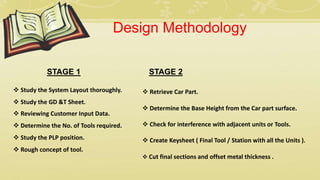
STAGE 1
 Study the System Layout thoroughly.
 Reviewing Customer Input Data.
 Determine the No. of Tools required.
 Study the GD &T Sheet.
 Study the PLP position.
 Rough concept of tool.
Design Methodology
STAGE 2
 Retrieve Car Part.
 Create Keysheet ( Final Tool / Station with all the Units ).
 Determine the Base Height from the Car part surface.
 Check for interference with adjacent units or Tools.
 Cut final sections and offset metal thickness .
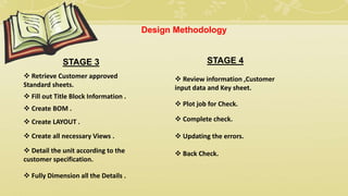
STAGE 3
 Retrieve Customer approved
Standard sheets.
 Detail the unit according to the
customer specification.
 Fill out Title Block Information .
 Create BOM .
 Create LAYOUT .
 Create all necessary Views .
 Fully Dimension all the Details .
Design Methodology
STAGE 4
 Review information ,Customer
input data and Key sheet.
 Complete check.
 Updating the errors.
 Back Check.
 Plot job for Check.
Design Output
3D Model & 2D Drawings
 Non Unitized Tools.
 Unitized Tools require 2 types of drawing sheets.
1. Key sheets.
2. Layout Sheets.
3. Part Detailing's.
 Tool Level detailing i.e. Key Sheet Layout
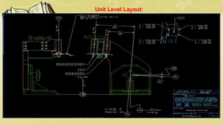
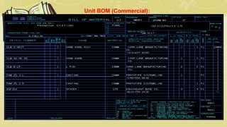
 Unit Level Detailing i.e. Layout & BOM
 Part Level Detailing
Type of Welding Fixtures Units
1) CLAMP UNIT.
2) PIN UNIT.
3) REST UNIT.
4) COMBINATION OF CLAMP & REST UNIT.
5) DUMP UNIT.
Typical Clamp Unit
CYLINDICATOR
SUB-PLATE
RISER
FLOW CONTROL
CYLINDER
L-BLOCK
NC-BLOCK
CLAMP ARM
BLADE
A COMBINED LOCATING, CLAMPING AND RESTING UNIT
RISER BRACKET
PIN
PROXIMITY SWITCH
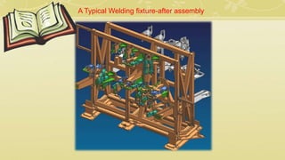
A Typical Welding fixture-after assembly
A Typical Welding fixture-in shop floor
Locating Pin Unit
Clamping Unit
Weld Gun
Robot
Welding
Electrodes
Car Part
Biw fixture
Thanks
Design Example :
Key Sheet Layout:
Key Sheet Layout:
Key Sheet Layout:
Unit Level Layout:
Unit Level Layout:
Unit Level Layout:
Make Part Detailing:
Unit BOM (Commercial):
Unit BOM (Make Parts):
Thanks

More Related Content

Biw fixture

  • 2. Definitions • Jig: A device that holds the work and locates the path of the tool. • Fixture: A device fixed to the worktable of a machine and locates the work in an exact position relative to the cutting tool. Superior Jig Flexible Fixturing Systems
  • 3. Fixtures • More of a permanent tool that is used for assembly purposes. • Typically does not have as much flexibility as a jig. • Most likely used for high volume production. • Made of durable materials such as tool steel, iron, aluminum alloys, etc.
  • 4. Other Fixture Examples • Used most commonly for welding and metal assembly work. • Typically used for products that must be very precise. • Sometimes are exposed to high temperatures and stresses
  • 5. Type of Fixtures (a) Turning fixtures (b) Milling fixtures (c) Fixture for grinding (d) Fixture for broaching (e) Fixture for boring/drilling (f) Tapping fixture (g) Fixture for welding (h) Assembling fixture Standard Parts Co.
  • 6. Fixture components • Fixture base • Fixture components and the workpiece are usually located on a base, which is securely fastened to the milling machine table. Standard Parts Co.
  • 7. Fixture components • Clamps • Clamps counteract forces from the feed of the table and rotation of the cutter. American Drill Bushing Co.
  • 8. Fixture components • Set blocks • Cutter set blocks are mounted on the fixture to properly position the milling cutter in relation to the workpiece.
  • 10. • Detailed design of locators • Detailed design of clamps • Detailed design of supports • Positions of locators • Positions of clamps • Positions of supports, if any • Type of locators • Type of clamps • Type of supports • Clamping forces and sequence The following outputs are included in the fixture element design:
  • 11. Fixture Design Criteria • Design specifications • Factory standards • Ease of use and safety • Economy
  • 12. Body In White (BIW) Fixtures Example : Fixture For Welding
  • 13. Various Aspects Of Fixture Design
  • 14. BIW – Weld Fixtures  Design Process/Methodology .  Different Types of Welding Fixture Units.  Design Inputs.  Design Outputs.
  • 15. Design Input  Functional and Performance Requirements.  Car Product.  System Layout.  Tool Information Sheet.  Weld Study Information.  Miscellaneous Information.
  • 16. Design Input 1. Functional and Performance Requirements  Product Assembly Process Sheet (Product Assembly Process Sheet is a sheet that gives the following information about the Car Product)  Parts Assembly Sequence.  Sequence Of Operation.  Cycle Time. 2. System Layout The following Points are to be considered while studying a System Layout .  Flow Of Parts.  Station Pitch.
  • 17. 3. Car Product The following Points are to be considered for the Car Product .  GD&T Sheet.  Part List.  CAD Files of the car part. Design Input 4. Tool Information Sheet The Tool Information Sheet consists of the following.  Tool Summary.  Tool Content Sheet .
  • 18. 5. Weld Study Information The Weld Study Information consists of the following.  Welding Spots.  Welding Guns. Design Input 6. Miscellaneous Information  Customer preferences. Standard parts to be used.  Informations derived from previous Designs and Development .  Title Sheet Informations to be filled.
  • 19. STAGE 1  Study the System Layout thoroughly.  Reviewing Customer Input Data.  Determine the No. of Tools required.  Study the GD &T Sheet.  Study the PLP position.  Rough concept of tool. Design Methodology STAGE 2  Retrieve Car Part.  Create Keysheet ( Final Tool / Station with all the Units ).  Determine the Base Height from the Car part surface.  Check for interference with adjacent units or Tools.  Cut final sections and offset metal thickness .
  • 20. STAGE 3  Retrieve Customer approved Standard sheets.  Detail the unit according to the customer specification.  Fill out Title Block Information .  Create BOM .  Create LAYOUT .  Create all necessary Views .  Fully Dimension all the Details . Design Methodology STAGE 4  Review information ,Customer input data and Key sheet.  Complete check.  Updating the errors.  Back Check.  Plot job for Check.
  • 21. Design Output 3D Model & 2D Drawings  Non Unitized Tools.  Unitized Tools require 2 types of drawing sheets. 1. Key sheets. 2. Layout Sheets. 3. Part Detailing's.  Tool Level detailing i.e. Key Sheet Layout  Unit Level Detailing i.e. Layout & BOM  Part Level Detailing
  • 22. Type of Welding Fixtures Units 1) CLAMP UNIT. 2) PIN UNIT. 3) REST UNIT. 4) COMBINATION OF CLAMP & REST UNIT. 5) DUMP UNIT.
  • 23. Typical Clamp Unit CYLINDICATOR SUB-PLATE RISER FLOW CONTROL CYLINDER L-BLOCK NC-BLOCK CLAMP ARM BLADE
  • 24. A COMBINED LOCATING, CLAMPING AND RESTING UNIT RISER BRACKET PIN PROXIMITY SWITCH
  • 25. A Typical Welding fixture-after assembly
  • 26. A Typical Welding fixture-in shop floor Locating Pin Unit Clamping Unit Weld Gun Robot Welding Electrodes Car Part
  • 39. Unit BOM (Make Parts):