Location via proxy:   [ UP ]  
[Report a bug]   [Manage cookies]                
SlideShare a Scribd company logo

1

BOILER
ACCESSORIES
PREPARED BY:
RUDRIK JOSHI
1

2

BOILER ACCESSORIES
• Boiler accessories are as follow :
• 1) Economiser
• 2) Air preheater
• 3) Superheater
2

3

ECONOMISER
3

4

WHAT IS ECONOMISER?
• Economiser is a device which increases temperature of feed water using
heat of flue gases leaving boiler through chimney.
• Flue gases are the combustion exhaust gases produced at power plants
consist of mostly nitrogen, carbon dioxide, water vapor, soot carbon
monoxide etc.
• It has been estimated that every 1% of fuel cost can be saved for every 6
degree centigrade rise in temperature of boiler feed water.
4

5

CONSTRUCTION AND WORKING OF
ECONOMISER
• It consist of large number of vertical cast
iron(steel water pipes).
• One end of vertical pipe connected with
horizontal pipe at upper side & another end
with lower side.
• The feed water enters into economiser
through the bottom pipe.
• Then, it comes into top pipe through the
vertical pipes.
• After that ,it comes into boiler for further
working.
5

6

CONSTRUCTION AND WORKING OF
ECONOMISER
• The hot flue gases coming from boiler
pass over the vertical tubes of
economiser.
• The heat transfer takes place from flue
gases to cold water rising in vertical tubes
of economiser.
• The heated feed water is supplied to the
boiler.
• TO PREVENT SOOT DEPOSIT ,the scrapers
S move up & down by chain and gears to
keep the external surface of the pipe
clean.
• A BLOW OFF COCK VALVE is provided at
back end of vertical pipes to remove
sediments deposited in the bottom boxes .
• A SAFETY VALVE provided at the end of the
pipe for the safety of the pipes. 6

7

7
Economiser_HIGH.mp4

8

TYPES OF ECONOMISER
1)Plain tube type economiser:
• In this type of economizer tubes
are made from cast iron to resist
corrosive action of flue gases.
• In this economiser the waste flue
gases flow outside the
economiser tubes and heat is
transferred to the feed water
flowing inside the tube.
• High efficiency of economiser
can be maintained by preventing
soot deposition.
8

9

TYPES OF ECONOMISER
2)Gilled tube type economiser:
• The gilled tube economiser made
up of cast iron which are fabricated
using graded cast iron fins.
• Efficiency is higher than plain type
economiser because in this type of
economiser there is a reduction in
size and higher heat transmission
due to gills on bare tube wall.
• Economiser also may have bare and
finned tubes.
9

10

CORROSION OF ECONOMISER AND
IT’S PREVENTION
• The corrosion and its prevention are very important for safe and efficient
working of economiser.
• Threre are two types of corrosion in economiser:
• 1) Internal corrosion
• 2) external corrosion
10

11

INTERNAL CORROSION
• CO2 forms carbonic acid(H2SO3)when dissolve in water. It is unstable and it ionizes into
HCO3- and H+ Ions and HCO3- further deform into CO3- and H+ ion.
• The H2SO3 is only one that exerting gas pressure and it must be removed at low PH level.
• NH3 forms ammonium hydroxide(NH4OH). It breaks into NH4+ and OH- Ions.
• Therefore NH4OH is responsible for exerting gas pressure and it must be removed at high
PH value.
• corrosion can be prevented by maintaining the pH value of water between 8 to 9 to reduce
its acidic effect.
11

12

EXTERNAL CORROSION
• External corrosion occur when if water vapour in flue gases condenses at tube
surfaces. Reduced tube surface temp. and presence of SO2 in exhaust gases
amplify corrosion rate.
• Sulphurous acid is form when SO2 is dissolve in free moisture in the flue gases,
sulphur trioxide may combine with superheated water vapour to form H2SO4 at
acid dew point.
• Maintaining feedwater temp at levels optimizes the potential level for low temp.
Corrosion attack on economiser, even when high sulphur fuels are used in thermal
power plant.
12

13

ADVANTAGES AND DISADVANTAGES
ADVANTAGES
• Higher feed water temperature tend to
reduce boiler thermal stresses, so life of
boiler increased.
• Economisers utilized waste heat from flue
gases, so fuel consumption of boiler
reduces.
• Increased evaporate capacity of boiler.
DISADVANTAGES
• Economisers placed at passage of the flow
of flue gases , so pressure drop take place
of flue gases (loss of draught)
13

14

AIR PREHEATER
14

15

WHAT IS AIR PREHEATER?
• Air preheater is a device which increases the temperature of air before it supply to
the furnace using heat from flue gases passing through chimney.
• The heat carried with the flue gases coming out of economiser is further utilised for
preheating the air before supplying to the combustion chamber.
• An increase of 20 degree centigrade in the air temp. increases the boiler efficiency
by 1%.
• It is a necessary equipment to supply hot air for drying the coal in pulverised fuel
systems to facilitate grinding and satisfactory combustion of fuel in the furnace.
15

16

BENEFITS OF PREHEATING
• The principal benefits of preheating are :
1. Improved combustion
2. Successful use of low grade fuel
3. Increased thermal efficiency
4. Saving in fuel consumption
5. Increased steam generation capacity
16

17

TYPES OF AIR PREHEATERS
• There are mainly two types of air preheaters:
1. Recuperative type
2. Regenerative type
17

18

TYPES OF AIR PREHEATERS
Recuperative type
• The recuperative heaters continuously
transfer the heat from hot gases to cold air.
Regenerative type
• The regenerative heater alternately gets
heated and cooled by the hot gases and cold
air.
• Unlike recuperative type , the regenerative
type is discontinuous in action and operates on
cycle.
18

19

RECUPERATIVE TYPE AIR
PREHEATER
• The two recuperative types of heat exchangers which are commonly used
for air-heating are described below:
1. Tubular air-heater
2. Plate type air-heater
19

20

TUBULAR AIR-HEATER
• Arrangement of tubular air-heater is shown in fig.
• The flue gases flow through the tubes and air is
passed over the outer surface of the tubes as
shown in fig.
• The horizontal baffles are provided as shown in
fig.to increase time of contact which will help for
higher heat transfer.
• The steel tubes 3 to 10m in height and 6to 8 cm in
diameter are commonly used.
20

21

TUBULAR AIR-HEATER
21
air preheater.mp4

22

PLATE AIR-HEATER
22
• A plate type heater is shown in fig.
• It consists of rectangular flat plates spaced
from 1.5 to 2.5cm apart leaving alternative
air and gas passages.
• This types of air heater is not used in
modern installations as it is more expansive
both as to flat cost and maintenance cost
compared with tubular air heaters.

23

REGENERATIVE HEAT EXCHANGER
23

24

REGENERATIVE HEAT EXCHANGER
• A typical type of stationary regenerative heat exchanger is shown in fig.
• The transfer of heat from hot gases to cold air is divided into two stages.
1.heating period
2.cooling period
• The heat of the hot gases flowing through the heat exchanger is transferred to the packing of
the heater and it is accumulated on the packing and the hot gases are cooled to sufficiently low
temp. before exhaust to atm.This stages is known as “Heating Period ”.
• In second stage, the cold air is passed through the hot packing where the heat is accumulated
and heat from the packing is transferred to the cold air.This stage is known as “Cooling period”.
24

25

ACID CORROSION AND IT’S
PREVENTION
• Combustion of sulphur in coal results in formation of SO2 and about 3to5% of the
SO2 is oxidized to SO3 depending on O2 content, moisture and temp. of flue gas.
• The SO2 and SO3 may then combine with moisture in the flue gas to form
sulphurous and sulphuric acids.
• Sulphurous acid will not form above dew point temp. and is seldom a problem.
• Sulphur trioxide is hygroscopic and absorbs moisture at temp. well above the dew
point ,resulting in the formation of sulphuric acid mist.
25

26

ACID CORROSION AND IT’S
PREVENTION
• The temp. at which this acid mist condenses to form sulphuric acid is called acid dew point.
• The condensed acid causes heavy corrosion of the metal surfaces.
• High excess air promotes oxidation of SO2 to SO3 which raises acid dew point as well as high moisture
content also increases the acid dew point.
• To avoid acid condensation and corrosion, air heater manufactures recommend minimum cold end
temperature and experience.
• The manufacturers have recommended 155 to 160 F cold end temperatures for tubular air heaters when
burning coal containing 1% sulphur.
• For coal containing 1 to 5% sulphur, recommended minimum cold end temperature lies betwwen 180 to
185 F.
26

27

ADVANTAGES AND DISADVANTAGES
ADVANTAGES
• Preheated air increases combustion rate and
then increases steam generations of boiler.
• Due to higher temp. of air , furnace temp.
increases, so low grade coal can be burnt
efficiently.
• Air heated by heat of exhaust gases. It reduces
fuel consumptions. Therefore thermal
efficiency of boiler increased.
DISADVANTAGES
• There are formation of clinkers, on the grate
due to higher combustion temp.
• Natural draught is not possible with air
preheater because of temp. of flue gases is
reduced, also pressure drop take place in the
flow of the flue gases. therefore forced
draught is required.
27

28

SUPERHEATER
28

29

INTRODUCTION
• The function of Super heater in the thermal power plant is to remove the
last traces of moisture from the saturated steam coming out of boiler and to
increase its temperature above saturation temperature as per requirement
at inlet of steam turbine.
• Superheating raises overall efficiency as well as avoids too much
condensation in last stages of turbine which avoids blade erosion.
29

30

INTRODUCTION
• The heat of combustion gases from furnace is utilised for removal of moisture from
steam and to superheat the steam.
• Super-heaters usually have several tube circuits in parallel with one or more return
bends, connected between headers.
• Heat from the hot gases to the vapour in the superheater is transferred at high
temperatures.
• Therefore primary section of superheater is arranged in counterflow and secondary
section in parallel flow to reduce the temp. stressing of the tube wall.
30

31

PRINCIPLE OF SUPERHEATER
• Principle of superheater is similar to steam generating tubes of boiler.
• The hot gases at high temperature sweep over superheater tubes and raise
the temperature of steam which magnitude depends upon exit gas
temperature leaving the superheater and gas velocity.
31

32

32
WORKING OF
SUPERHEATER(ANIMATION
EXPLAIN).mp4

33

CLASSIFICATION OF
SUPERHEATERS
• Based on the mode of heat transfer:
1) Convective Superheater
2) Radiant Superheater
3) Pendant Superheater (Combined Superheater)
33

34

CLASSIFICATION OF
SUPERHEATERS
• Based on their position in the furnace w.r.t. water tubes.
1) Overdeck Superheater
2) Innerdeck Superheater
3) Inner tube Superheater
4) Inner bank Superheater
34

35

CONVECTIVE SUPERHEATER
• They are located in the convective zone of the furnace. They absorbs heat from the flue
gases through convection.
• The convective superheater gives rising characteristics i.e. the temperature of superheater
increases with the increase in steam output.
• Because with the increase the steam output both gas flow over superheater tubes and
steam flow inside the tubes increase which causes increase in heat transfer rate and mean
temperature difference.
35

36

CONVECTIVE SUPERHEATER
36

37

RADIENT SUPERHEATER
• They are located in the furnace between the furnace walls. It absorbs heat from burning fuel through
radiation.
• It has two main disadvantages:
1) It may get overheated due to high temperature of furnace.
2) It has a dropping characteristics i .e. the temperature of superheat falls with the increase in steam output.
Because with the increase in steam output the furnace temperature rises at a much less rate than the
steam output.
37

38

RADIENT SUPERHEATER
38

39

PENDANT SUPERHEATER
• In this Superheater both Convective and Radiant Superheaters are arranged in series in the
path of the flue gases.
• Radiant superheater receives heat from the flue gases by radiation and convective
superheater receives heat by convection.
• About 3/4th of convective surface is made counter flow while the remaining l/4th is parallel
flow. If the entire coils are counter flow then exit end of the superheater will be subjected
maximum temperature difference.
39

40

40

41

INNERDECK SUPERHEATER
• In case of the Innerdeck
Superheater, Superheater is
placed between the
evaporator water tubes.
• Here, the heat is carried by the
convection. But it also receives
some heat by radiation.
41

42

OVERDECK SUPERHEATER
• In the Overdeck
Superheater, Superheater
is placed above the
evaporator tubes.
• In this type the heat is
received by the
convection.
42

43

INNER TUBE SUPERHEATER
• The Inner tube Superheaters
are placed between the two
evaporator tubes.
43

44

INNER BANK SUPERHEATER
• In the Inner bank superheaters,
the bank of superheater tubes is
placed between the evaporator
tubes.
44

45

METHOD FOR CONTROLLING SUPERHEAT
TEMPERATURE
1. Bypassing the furnace gas around the superheater
2. Tilting burners in furnace
3. Auxiliary burners
4. Desuperheater using water supply
5. Pre condensing using water sprey
6. Gas recirulation
7. Twin furnace arrangement
8. Coil immersion in the boiler drum
45

46

46

47

REHEATERS
• The function of the Reheater is to resuperheat the partly expanded steam from the
turbine.
• This is done so that the steam remains dry as far as possible through the last stage
of the turbine.
• The reheater is generally located before or after the convective superheater in the
convective one of utility boilers.
• In modern high pressure boilers the reheaters are in two sections. A primary
section is placed in the convective zone and the secondary section is placed just at
the furnace exit hanging from the top.
47

48

48

More Related Content

Boiler accessories

  • 2. BOILER ACCESSORIES • Boiler accessories are as follow : • 1) Economiser • 2) Air preheater • 3) Superheater 2
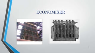
  • 4. WHAT IS ECONOMISER? • Economiser is a device which increases temperature of feed water using heat of flue gases leaving boiler through chimney. • Flue gases are the combustion exhaust gases produced at power plants consist of mostly nitrogen, carbon dioxide, water vapor, soot carbon monoxide etc. • It has been estimated that every 1% of fuel cost can be saved for every 6 degree centigrade rise in temperature of boiler feed water. 4
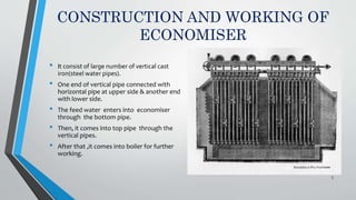
  • 5. CONSTRUCTION AND WORKING OF ECONOMISER • It consist of large number of vertical cast iron(steel water pipes). • One end of vertical pipe connected with horizontal pipe at upper side & another end with lower side. • The feed water enters into economiser through the bottom pipe. • Then, it comes into top pipe through the vertical pipes. • After that ,it comes into boiler for further working. 5
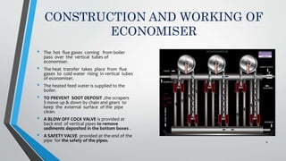
  • 6. CONSTRUCTION AND WORKING OF ECONOMISER • The hot flue gases coming from boiler pass over the vertical tubes of economiser. • The heat transfer takes place from flue gases to cold water rising in vertical tubes of economiser. • The heated feed water is supplied to the boiler. • TO PREVENT SOOT DEPOSIT ,the scrapers S move up & down by chain and gears to keep the external surface of the pipe clean. • A BLOW OFF COCK VALVE is provided at back end of vertical pipes to remove sediments deposited in the bottom boxes . • A SAFETY VALVE provided at the end of the pipe for the safety of the pipes. 6
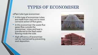
  • 8. TYPES OF ECONOMISER 1)Plain tube type economiser: • In this type of economizer tubes are made from cast iron to resist corrosive action of flue gases. • In this economiser the waste flue gases flow outside the economiser tubes and heat is transferred to the feed water flowing inside the tube. • High efficiency of economiser can be maintained by preventing soot deposition. 8
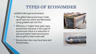
  • 9. TYPES OF ECONOMISER 2)Gilled tube type economiser: • The gilled tube economiser made up of cast iron which are fabricated using graded cast iron fins. • Efficiency is higher than plain type economiser because in this type of economiser there is a reduction in size and higher heat transmission due to gills on bare tube wall. • Economiser also may have bare and finned tubes. 9
  • 10. CORROSION OF ECONOMISER AND IT’S PREVENTION • The corrosion and its prevention are very important for safe and efficient working of economiser. • Threre are two types of corrosion in economiser: • 1) Internal corrosion • 2) external corrosion 10
  • 11. INTERNAL CORROSION • CO2 forms carbonic acid(H2SO3)when dissolve in water. It is unstable and it ionizes into HCO3- and H+ Ions and HCO3- further deform into CO3- and H+ ion. • The H2SO3 is only one that exerting gas pressure and it must be removed at low PH level. • NH3 forms ammonium hydroxide(NH4OH). It breaks into NH4+ and OH- Ions. • Therefore NH4OH is responsible for exerting gas pressure and it must be removed at high PH value. • corrosion can be prevented by maintaining the pH value of water between 8 to 9 to reduce its acidic effect. 11
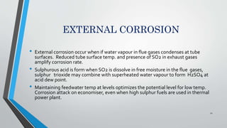
  • 12. EXTERNAL CORROSION • External corrosion occur when if water vapour in flue gases condenses at tube surfaces. Reduced tube surface temp. and presence of SO2 in exhaust gases amplify corrosion rate. • Sulphurous acid is form when SO2 is dissolve in free moisture in the flue gases, sulphur trioxide may combine with superheated water vapour to form H2SO4 at acid dew point. • Maintaining feedwater temp at levels optimizes the potential level for low temp. Corrosion attack on economiser, even when high sulphur fuels are used in thermal power plant. 12
  • 13. ADVANTAGES AND DISADVANTAGES ADVANTAGES • Higher feed water temperature tend to reduce boiler thermal stresses, so life of boiler increased. • Economisers utilized waste heat from flue gases, so fuel consumption of boiler reduces. • Increased evaporate capacity of boiler. DISADVANTAGES • Economisers placed at passage of the flow of flue gases , so pressure drop take place of flue gases (loss of draught) 13
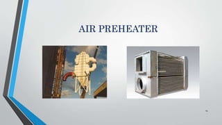
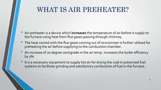
  • 15. WHAT IS AIR PREHEATER? • Air preheater is a device which increases the temperature of air before it supply to the furnace using heat from flue gases passing through chimney. • The heat carried with the flue gases coming out of economiser is further utilised for preheating the air before supplying to the combustion chamber. • An increase of 20 degree centigrade in the air temp. increases the boiler efficiency by 1%. • It is a necessary equipment to supply hot air for drying the coal in pulverised fuel systems to facilitate grinding and satisfactory combustion of fuel in the furnace. 15
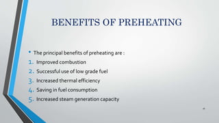
  • 16. BENEFITS OF PREHEATING • The principal benefits of preheating are : 1. Improved combustion 2. Successful use of low grade fuel 3. Increased thermal efficiency 4. Saving in fuel consumption 5. Increased steam generation capacity 16
  • 17. TYPES OF AIR PREHEATERS • There are mainly two types of air preheaters: 1. Recuperative type 2. Regenerative type 17
  • 18. TYPES OF AIR PREHEATERS Recuperative type • The recuperative heaters continuously transfer the heat from hot gases to cold air. Regenerative type • The regenerative heater alternately gets heated and cooled by the hot gases and cold air. • Unlike recuperative type , the regenerative type is discontinuous in action and operates on cycle. 18
  • 19. RECUPERATIVE TYPE AIR PREHEATER • The two recuperative types of heat exchangers which are commonly used for air-heating are described below: 1. Tubular air-heater 2. Plate type air-heater 19
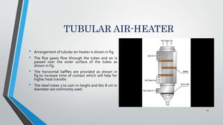
  • 20. TUBULAR AIR-HEATER • Arrangement of tubular air-heater is shown in fig. • The flue gases flow through the tubes and air is passed over the outer surface of the tubes as shown in fig. • The horizontal baffles are provided as shown in fig.to increase time of contact which will help for higher heat transfer. • The steel tubes 3 to 10m in height and 6to 8 cm in diameter are commonly used. 20
  • 22. PLATE AIR-HEATER 22 • A plate type heater is shown in fig. • It consists of rectangular flat plates spaced from 1.5 to 2.5cm apart leaving alternative air and gas passages. • This types of air heater is not used in modern installations as it is more expansive both as to flat cost and maintenance cost compared with tubular air heaters.
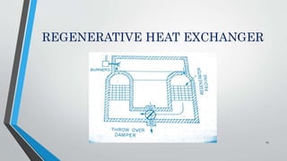
  • 24. REGENERATIVE HEAT EXCHANGER • A typical type of stationary regenerative heat exchanger is shown in fig. • The transfer of heat from hot gases to cold air is divided into two stages. 1.heating period 2.cooling period • The heat of the hot gases flowing through the heat exchanger is transferred to the packing of the heater and it is accumulated on the packing and the hot gases are cooled to sufficiently low temp. before exhaust to atm.This stages is known as “Heating Period ”. • In second stage, the cold air is passed through the hot packing where the heat is accumulated and heat from the packing is transferred to the cold air.This stage is known as “Cooling period”. 24
  • 25. ACID CORROSION AND IT’S PREVENTION • Combustion of sulphur in coal results in formation of SO2 and about 3to5% of the SO2 is oxidized to SO3 depending on O2 content, moisture and temp. of flue gas. • The SO2 and SO3 may then combine with moisture in the flue gas to form sulphurous and sulphuric acids. • Sulphurous acid will not form above dew point temp. and is seldom a problem. • Sulphur trioxide is hygroscopic and absorbs moisture at temp. well above the dew point ,resulting in the formation of sulphuric acid mist. 25
  • 26. ACID CORROSION AND IT’S PREVENTION • The temp. at which this acid mist condenses to form sulphuric acid is called acid dew point. • The condensed acid causes heavy corrosion of the metal surfaces. • High excess air promotes oxidation of SO2 to SO3 which raises acid dew point as well as high moisture content also increases the acid dew point. • To avoid acid condensation and corrosion, air heater manufactures recommend minimum cold end temperature and experience. • The manufacturers have recommended 155 to 160 F cold end temperatures for tubular air heaters when burning coal containing 1% sulphur. • For coal containing 1 to 5% sulphur, recommended minimum cold end temperature lies betwwen 180 to 185 F. 26
  • 27. ADVANTAGES AND DISADVANTAGES ADVANTAGES • Preheated air increases combustion rate and then increases steam generations of boiler. • Due to higher temp. of air , furnace temp. increases, so low grade coal can be burnt efficiently. • Air heated by heat of exhaust gases. It reduces fuel consumptions. Therefore thermal efficiency of boiler increased. DISADVANTAGES • There are formation of clinkers, on the grate due to higher combustion temp. • Natural draught is not possible with air preheater because of temp. of flue gases is reduced, also pressure drop take place in the flow of the flue gases. therefore forced draught is required. 27
  • 29. INTRODUCTION • The function of Super heater in the thermal power plant is to remove the last traces of moisture from the saturated steam coming out of boiler and to increase its temperature above saturation temperature as per requirement at inlet of steam turbine. • Superheating raises overall efficiency as well as avoids too much condensation in last stages of turbine which avoids blade erosion. 29
  • 30. INTRODUCTION • The heat of combustion gases from furnace is utilised for removal of moisture from steam and to superheat the steam. • Super-heaters usually have several tube circuits in parallel with one or more return bends, connected between headers. • Heat from the hot gases to the vapour in the superheater is transferred at high temperatures. • Therefore primary section of superheater is arranged in counterflow and secondary section in parallel flow to reduce the temp. stressing of the tube wall. 30
  • 31. PRINCIPLE OF SUPERHEATER • Principle of superheater is similar to steam generating tubes of boiler. • The hot gases at high temperature sweep over superheater tubes and raise the temperature of steam which magnitude depends upon exit gas temperature leaving the superheater and gas velocity. 31
  • 33. CLASSIFICATION OF SUPERHEATERS • Based on the mode of heat transfer: 1) Convective Superheater 2) Radiant Superheater 3) Pendant Superheater (Combined Superheater) 33
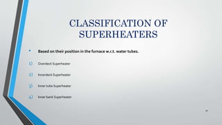
  • 34. CLASSIFICATION OF SUPERHEATERS • Based on their position in the furnace w.r.t. water tubes. 1) Overdeck Superheater 2) Innerdeck Superheater 3) Inner tube Superheater 4) Inner bank Superheater 34
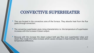
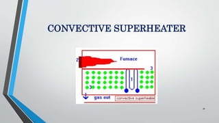
  • 35. CONVECTIVE SUPERHEATER • They are located in the convective zone of the furnace. They absorbs heat from the flue gases through convection. • The convective superheater gives rising characteristics i.e. the temperature of superheater increases with the increase in steam output. • Because with the increase the steam output both gas flow over superheater tubes and steam flow inside the tubes increase which causes increase in heat transfer rate and mean temperature difference. 35
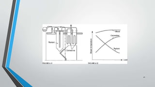
  • 37. RADIENT SUPERHEATER • They are located in the furnace between the furnace walls. It absorbs heat from burning fuel through radiation. • It has two main disadvantages: 1) It may get overheated due to high temperature of furnace. 2) It has a dropping characteristics i .e. the temperature of superheat falls with the increase in steam output. Because with the increase in steam output the furnace temperature rises at a much less rate than the steam output. 37
  • 39. PENDANT SUPERHEATER • In this Superheater both Convective and Radiant Superheaters are arranged in series in the path of the flue gases. • Radiant superheater receives heat from the flue gases by radiation and convective superheater receives heat by convection. • About 3/4th of convective surface is made counter flow while the remaining l/4th is parallel flow. If the entire coils are counter flow then exit end of the superheater will be subjected maximum temperature difference. 39
  • 40. 40
  • 41. INNERDECK SUPERHEATER • In case of the Innerdeck Superheater, Superheater is placed between the evaporator water tubes. • Here, the heat is carried by the convection. But it also receives some heat by radiation. 41
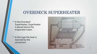
  • 42. OVERDECK SUPERHEATER • In the Overdeck Superheater, Superheater is placed above the evaporator tubes. • In this type the heat is received by the convection. 42
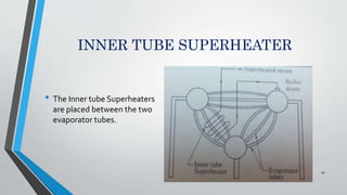
  • 43. INNER TUBE SUPERHEATER • The Inner tube Superheaters are placed between the two evaporator tubes. 43
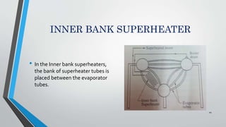
  • 44. INNER BANK SUPERHEATER • In the Inner bank superheaters, the bank of superheater tubes is placed between the evaporator tubes. 44
  • 45. METHOD FOR CONTROLLING SUPERHEAT TEMPERATURE 1. Bypassing the furnace gas around the superheater 2. Tilting burners in furnace 3. Auxiliary burners 4. Desuperheater using water supply 5. Pre condensing using water sprey 6. Gas recirulation 7. Twin furnace arrangement 8. Coil immersion in the boiler drum 45
  • 46. 46
  • 47. REHEATERS • The function of the Reheater is to resuperheat the partly expanded steam from the turbine. • This is done so that the steam remains dry as far as possible through the last stage of the turbine. • The reheater is generally located before or after the convective superheater in the convective one of utility boilers. • In modern high pressure boilers the reheaters are in two sections. A primary section is placed in the convective zone and the secondary section is placed just at the furnace exit hanging from the top. 47
  • 48. 48