Calculation note suez canal cable stayed bridge
•
37 likes•8,821 views

This document provides details on the design of a cable-stayed bridge project over the Suez Canal. The key aspects are: 1) The bridge has a total length of 730m with a 165m side span and 400m main span. It consists of a concrete box girder deck, H-shaped concrete pylons that are 150m tall, and 16 pre-tensioned steel strand cables on each side. 2) Analyses were conducted to determine cable forces, member forces and deformations due to self-weight, live loads, wind, and earthquakes. The bridge was found to meet design criteria. 3) The main components of the deck, pylons, and cables are
Report
Share

Calculation note suez canal cable stayed bridge
- 1. 1 Kafr El Sheikh University Faculty of Engineering Civil Engineering Department Suez-Canal Cable-Stayed Bridge Project (The Graduation Project) Prepared By / Mohamed Ahmed Elfeky Mohammed Abdelkawy Ahmed Bahgat Zamil 4th Year Civil
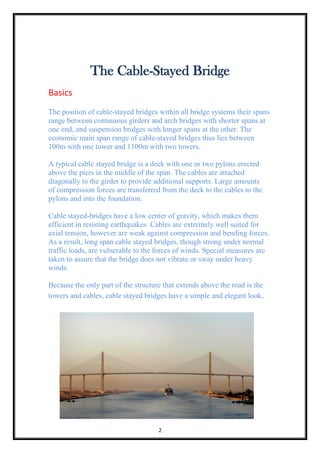
- 2. 2 The Cable-Stayed Bridge Basics The position of cable-stayed bridges within all bridge systems their spans range between continuous girders and arch bridges with shorter spans at one end, and suspension bridges with longer spans at the other. The economic main span range of cable-stayed bridges thus lies between 100m with one tower and 1100m with two towers. A typical cable stayed bridge is a deck with one or two pylons erected above the piers in the middle of the span. The cables are attached diagonally to the girder to provide additional supports. Large amounts of compression forces are transferred from the deck to the cables to the pylons and into the foundation. Cable stayed-bridges have a low center of gravity, which makes them efficient in resisting earthquakes. Cables are extremely well suited for axial tension, however are weak against compression and bending forces. As a result, long span cable stayed bridges, though strong under normal traffic loads, are vulnerable to the forces of winds. Special measures are taken to assure that the bridge does not vibrate or sway under heavy winds. Because the only part of the structure that extends above the road is the towers and cables, cable stayed bridges have a simple and elegant look.
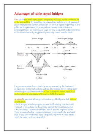
- 3. 3 Advantages of cable-stayed bridges: First of all the bending moments are greatly reduced by the load transfer of the stay cables, By installing the stay cables with their predetermined precise lengths the support conditions for a beam rigidly supported at the cable anchor points can be achieved and thus the moments from permanent loads are minimized, Even for live loads the bending moments of the beam elastically supported by the stay cables remain small. Large compression forces in the beam are caused by the horizontal components of the inclined stay cables. The normal forces in the main and side span equal one another so that only uplift forces have to be anchored in the abutments which act as hold-down piers. A second important advantage of cable-stayed bridges is their ease of construction; - Arch bridges with large spans are not stable during erection until The arch is closed and the horizontal support forces are anchored. - Self-anchored suspension bridges, which may be required when Their horizontal cable component cannot economically be anchored Due to bad soil conditions, need temporary supports of their beams until the main cables are installed.
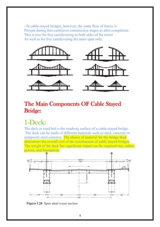
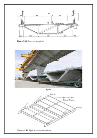
- 4. 4 - In cable-stayed bridges, however, the same flow of forces is Present during free-cantilever construction stages as after completion. This is true for free cantilevering to both sides of the tower As well as for free cantilevering the main span only. The Main Components OF Cable Stayed Bridge: 1-Deck: The deck or road bed is the roadway surface of a cable-stayed bridge. The deck can be made of different materials such as steel, concrete or composite steel-concrete. The choice of material for the bridge deck determines the overall cost of the construction of cable stayed bridges. The weight of the deck has significant impact on the required stay cables, pylons, and foundation.
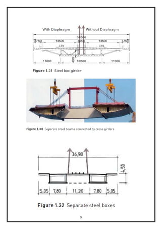
- 5. 5
- 6. 6 Pylon
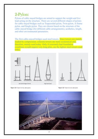
- 7. 7 2-Pylon: Pylons of cable stayed bridges are aimed to support the weight and live load acting on the structure. There are several different shapes of pylons for cable stayed bridges such as Trapezoidal pylon, Twin pylon, A-frame pylon, and Single pylon. They are chosen based on the structure of the cable stayed bridge (for different cable arrangements), aesthetics, length, and other environmental parameters. The first cable-stayed bridges used steel towers. Since towers are mainly loaded by compression, concrete towers are more economical and, therefore, mainly used today. Only if extremely bad foundation conditions would require very long piles, are the lighter steel towers used today.
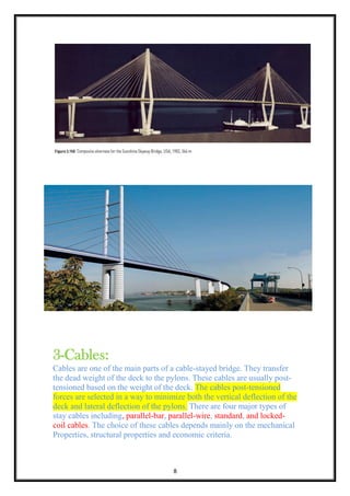
- 8. 8 3-Cables: Cables are one of the main parts of a cable-stayed bridge. They transfer the dead weight of the deck to the pylons. These cables are usually post- tensioned based on the weight of the deck. The cables post-tensioned forces are selected in a way to minimize both the vertical deflection of the deck and lateral deflection of the pylons. There are four major types of stay cables including, parallel-bar, parallel-wire, standard, and locked- coil cables. The choice of these cables depends mainly on the mechanical Properties, structural properties and economic criteria.
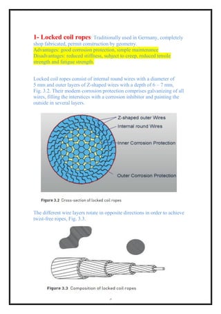
- 9. 9 1- Locked coil ropes: Traditionally used in Germany, completely shop fabricated, permit construction by geometry. Advantages: good corrosion protection, simple maintenance Disadvantages: reduced stiffness, subject to creep, reduced tensile strength and fatigue strength. Locked coil ropes consist of internal round wires with a diameter of 5 mm and outer layers of Z-shaped wires with a depth of 6 – 7 mm, Fig. 3.2. Their modern corrosion protection comprises galvanizing of all wires, filling the interstices with a corrosion inhibitor and painting the outside in several layers. The different wire layers rotate in opposite directions in order to achieve twist-free ropes, Fig. 3.3.
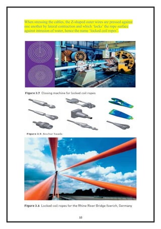
- 10. 10 When stressing the cables, the Z-shaped outer wires are pressed against one another by lateral contraction and which ‘locks’ the rope surface against intrusion of water, hence the name ‘locked coil ropes’.
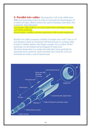
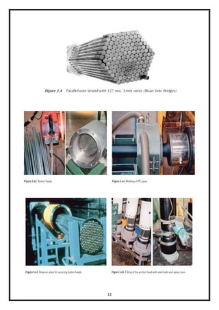
- 11. 11 2- Parallel wire cables: Developed by LAP in the 1960s from BBR post-tensioning system in order to overcome the disadvantages of Locked coil ropes, almost exclusively used in Germany since then, also completely shop-fabricated. Advantages: high stiffness, no creep, high tensile and fatigue strength with Hiam-anchorage Disadvantage: complex corrosion protection with several components Parallel wire cables comprise a bundle of straight wires with 7 mm or 1⁄4 inch diameter which are anchored with button heads in a retainer plate. In order to further improve the fatigue strength, the so-called ‘HiAm’ anchorage was developed and investigated in many tests. The basic design idea is to anchor the individual wires gradually by lateral pressure exerted by small steel balls into which the wires are broomed-out inside a conical anchor head.
- 12. 12
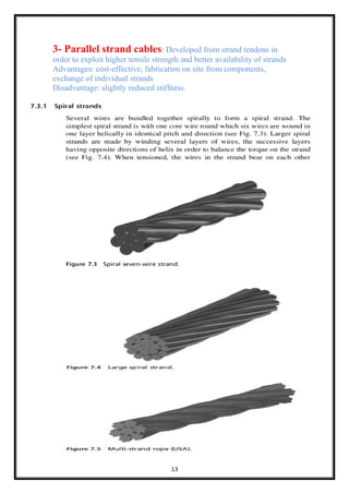
- 13. 13 3- Parallel strand cables: Developed from strand tendons in order to exploit higher tensile strength and better availability of strands Advantages: cost-effective, fabrication on site from components, exchange of individual strands Disadvantage: slightly reduced stiffness.
- 14. 14
- 15. 15
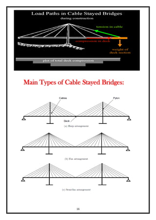
- 16. 16 Main Types of Cable Stayed Bridges:
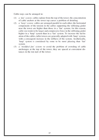
- 17. 17
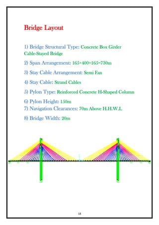
- 18. 18 Bridge Layout 1) Bridge Structural Type: Concrete Box Girder Cable-Stayed Bridge 2) Span Arrangement: 165+400+165=730m 3) Stay Cable Arrangement: Semi Fan 4) Stay Cable: Strand Cables 5) Pylon Type: Reinforced Concrete H-Shaped Column 6) Pylon Height: 150m 7) Navigation Clearances: 70m Above H.H.W.L 8) Bridge Width: 20m
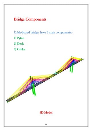
- 19. 19 Bridge Components Cable-Stayed bridges have 3 main components:- 1) Pylon 2) Deck 3) Cables 3D Model
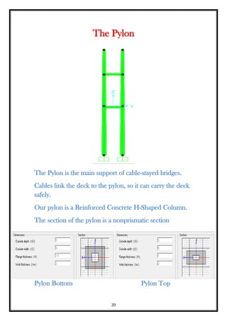
- 20. 20 The Pylon The Pylon is the main support of cable-stayed bridges. Cables link the deck to the pylon, so it can carry the deck safely. Our pylon is a Reinforced Concrete H-Shaped Column. The section of the pylon is a nonprismatic section Pylon Bottom Pylon Top
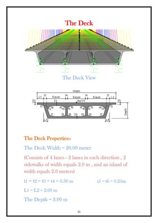
- 21. 21 The Deck The Deck View The Deck Properties:- The Deck Width = 20.00 meter (Consists of 4 lanes - 2 lanes in each direction , 2 sidewalks of width equals 2.0 m , and an island of width equals 2.0 meters) t1 = t2 = t3 = t4 = 0.30 m t5 = t6 = 0.25m L1 = L2 = 2.00 m The Depth = 3.00 m
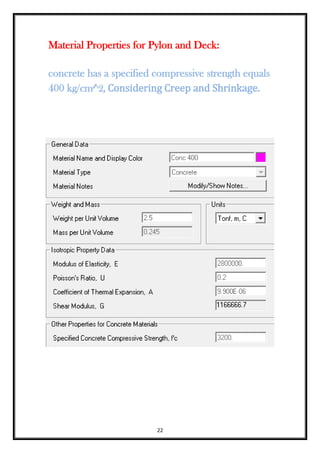
- 22. 22 Material Properties for Pylon and Deck: concrete has a specified compressive strength equals 400 kg/cm^2, Considering Creep and Shrinkage.
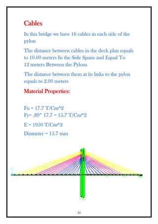
- 23. 23 Cables In this bridge we have 16 cables in each side of the pylon The distance between cables in the deck plan equals to 10.00 meters In the Side Spans and Equal To 12 meters Between the Pylons The distance between them at its links to the pylon equals to 2.00 meters Material Properties: Fu = 17.7 T/Cm^2 Fy= .89* 17.7 = 15.7 T/Cm^2 E = 1950 T/Cm^2 Diameter = 15.7 mm
- 24. 24 Modeling Steps (Using CSI Bridge Program) 1) Drawing the layout line of the bridge. The layout has 2 stations the 1st at 0.0 and the 2nd at 730.00. 2) Defining the deck sec. which is box girder has 3 vents. 3) Defining Lanes. 4) Defining and drawing the pylon. 5) Defining and drawing the rigid links to link the deck sec. to cables as one unit. 6) Defining springs. 7) Solving the model to get the deformation due to dead load. 8) Defining the cables (Diameter & Pretension Force) which achieve deformation equals to zero. 9) Defining the design vehicle and vehicle class. 10) Defining All Cases Of Moving Load. 11) Solving due to moving load and getting deformation.
- 25. 25 12) Defining the Earthquake loads Using Static Analysis (Seismic Coefficient Method) and Safety Was Checked by Dynamic Analysis (Time History Method). 15) Solving the model due to earthquake forces. 16) Defining the wind loads. 17) Solving. 18) Defining load combinations. 19) Design the bridge. Philosophy of Analysis: 1-Find the value of cable tension that will give optimum deck profile for final model. 2- Stage construction analysis to find cable force during erection. 3- Final checks with seismic, Wind and other effects
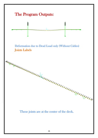
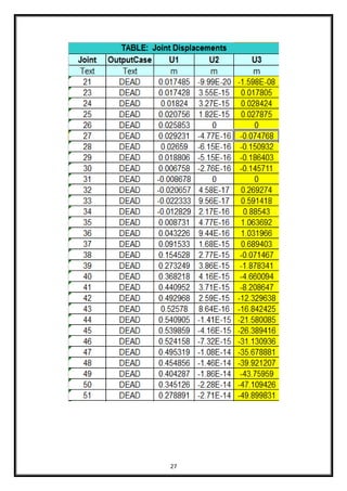
- 26. 26 The Program Outputs: Deformation due to Dead Load only (Without Cables) Joints Labels These joints are at the center of the deck.
- 27. 27
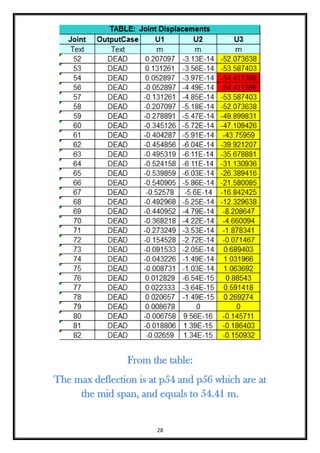
- 28. 28 From the table: The max deflection is at p54 and p56 which are at the mid span, and equals to 54.41 m.
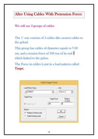
- 29. 29 We will use 3 groups of cables The 1st one consists of 5 cables (the nearest cables to the pylon) This group has cables of diameter equals to 7.00 cm, and a tension force of 340 ton of its end I which linked to the pylon. The Force in cables is put in a load pattern called Target. After Using Cables With Pretension Force:
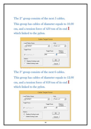
- 30. 30 The 2nd group consists of the next 5 cables. This group has cables of diameter equals to 10.00 cm, and a tension force of 450 ton of its end I which linked to the pylon. The 3rd group consists of the next 6 cables. This group has cables of diameter equals to 12.00 cm, and a tension force of 618 ton of its end I which linked to the pylon.
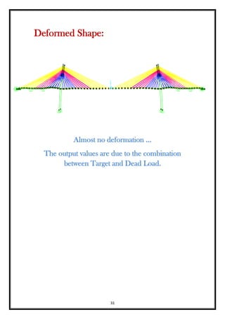
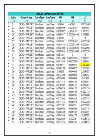
- 31. 31 Deformed Shape: Almost no deformation … The output values are due to the combination between Target and Dead Load.
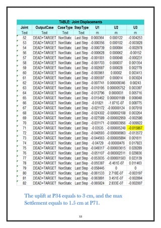
- 32. 32
- 33. 33 The uplift at P34 equals to 3 cm, and the max Settlement equals to 1.5 cm at P71.
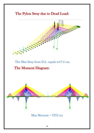
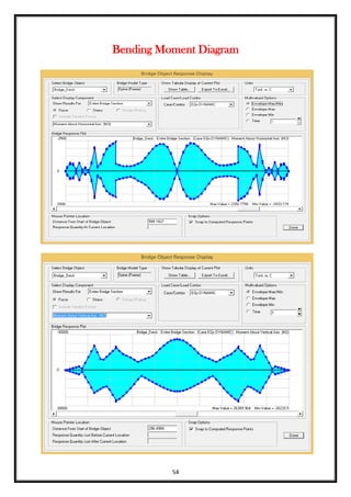
- 34. 34 The Pylon Sway due to Dead Load: The Max Sway from D.L. equals to17.6 cm. The Moment Diagram: Max Moment = 7272 t.m
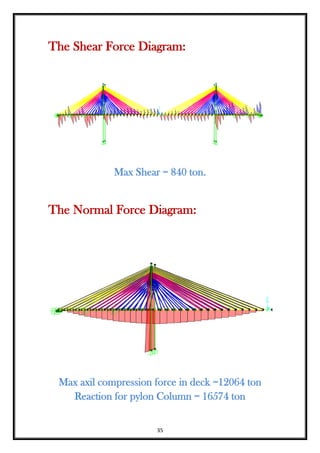
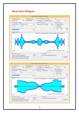
- 35. 35 The Shear Force Diagram: Max Shear = 840 ton. The Normal Force Diagram: Max axil compression force in deck =12064 ton Reaction for pylon Column = 16574 ton
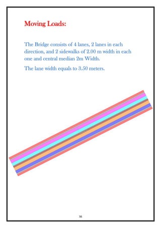
- 36. 36 Moving Loads: The Bridge consists of 4 lanes, 2 lanes in each direction, and 2 sidewalks of 2.00 m width in each one and central median 2m Width. The lane width equals to 3.50 meters.
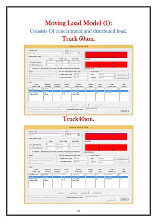
- 37. 37 Moving Load Model (1): Consists Of concentrated and distributed load. Truck 60ton. Truck40ton.
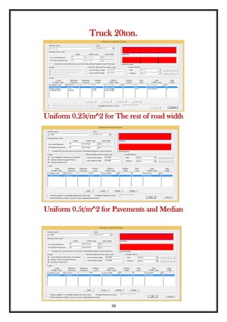
- 38. 38 Truck 20ton. Uniform 0.25t/m^2 for The rest of road width Uniform 0.5t/m^2 for Pavements and Median
- 39. 39
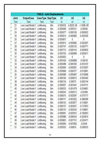
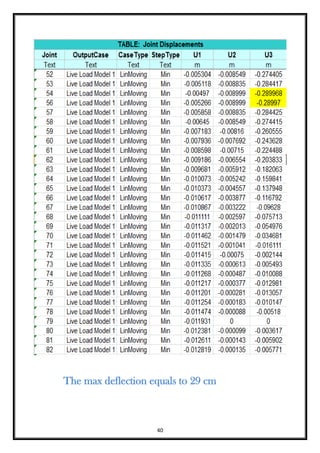
- 40. 40 The max deflection equals to 29 cm
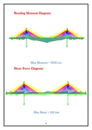
- 41. 41 Bending Moment Diagram: Max Moment = 3956 t.m Shear Force Diagram: Max Shear = 243 ton
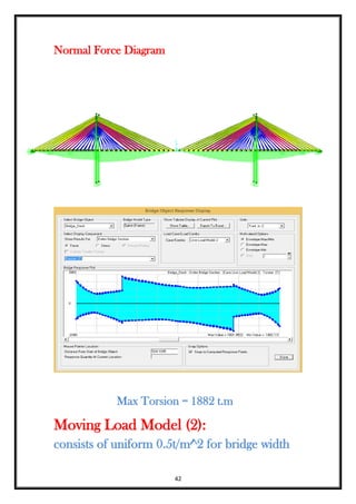
- 42. 42 Normal Force Diagram Max Torsion = 1882 t.m Moving Load Model (2): consists of uniform 0.5t/m^2 for bridge width
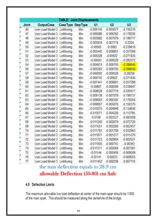
- 43. 43 the max deflection equals to 28.9 cm allowable Deflection (50-80) cm Safe
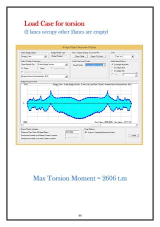
- 44. 44 Load Case for torsion (2 lanes occupy other 2lanes are empty) Max Torsion Moment = 2606 t.m
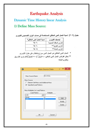
- 45. 45 Earthquake Analysis Dynamic Time History linear Analysis 1) Define Mass Source:
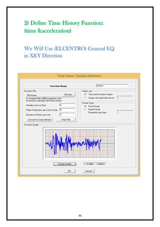
- 46. 46 2) Define Time History Function: (time &acceleration) We Will Use (ELCENTRO) General EQ in X&Y Direction
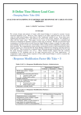
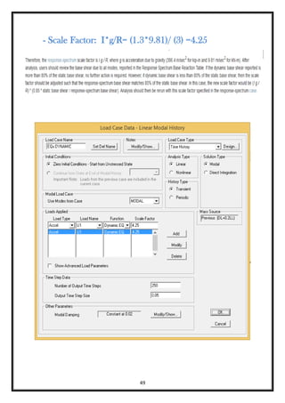
- 47. 47 3) Define Time History Load Case: - Damping Ratio: Take (2%) - Response Modification Factor (R): Take = 3
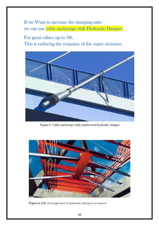
- 48. 48 If we Want to increase the damping ratio we can use cable anchorage with Hydraulic Damper For great values up to 5%. This is reducing the response of the super structure.
- 49. 49 - Scale Factor: I*g/R= (1.3*9.81)/ (3) =4.25
- 50. 50
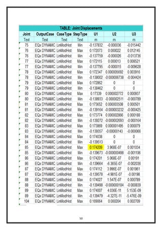
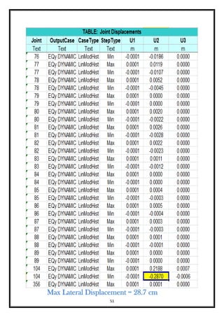
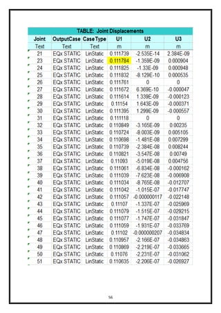
- 51. 51 Max Lateral Displacement = 28.7 cm
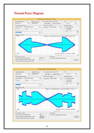
- 52. 52 Normal Force Diagram
- 53. 53 Shear Force Diagram
- 54. 54 Bending Moment Diagram
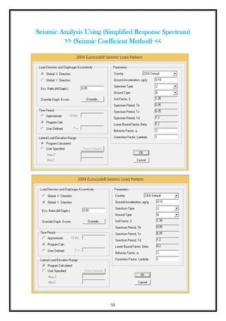
- 55. 55 Seismic Analysis Using (Simplified Response Spectrum) >> (Seismic Coefficient Method) <<
- 56. 56
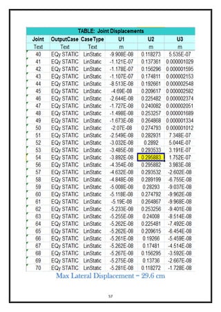
- 57. 57 Max Lateral Displacement = 29.6 cm
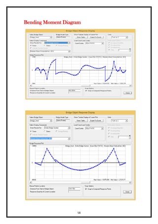
- 58. 58 Bending Moment Diagram
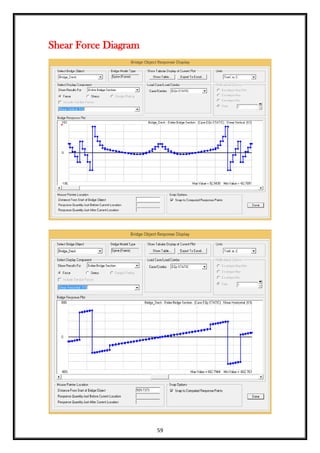
- 59. 59 Shear Force Diagram
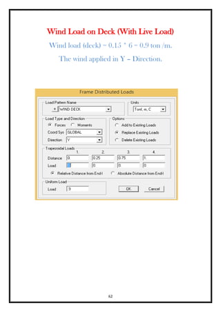
- 61. 61 Wind Loads Wind load which affect on the deck of the bridge and on the trucks can be calculated from the EGYPTIAN code of loads as following:
- 62. 62 Wind Load on Deck (With Live Load) Wind load (deck) = 0.15 * 6 = 0.9 ton /m. The wind applied in Y – Direction.
- 63. 63
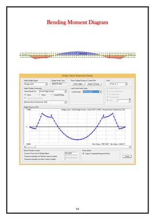
- 64. 64 Bending Moment Diagram
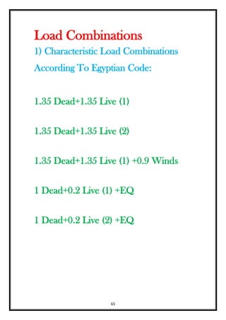
- 65. 65 Load Combinations 1) Characteristic Load Combinations According To Egyptian Code: 1.35 Dead+1.35 Live (1) 1.35 Dead+1.35 Live (2) 1.35 Dead+1.35 Live (1) +0.9 Winds 1 Dead+0.2 Live (1) +EQ 1 Dead+0.2 Live (2) +EQ
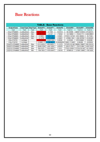
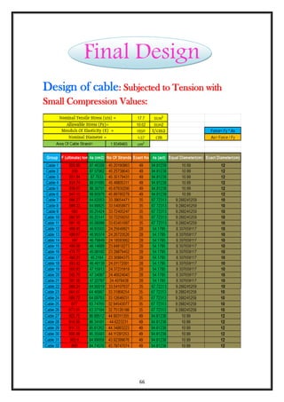
- 66. 66 Final Design Design of cable: Subjected to Tension with Small Compression Values:
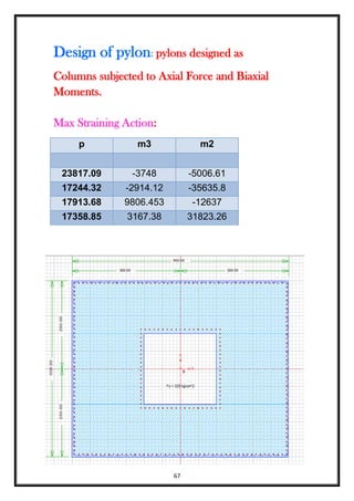
- 67. 67 Design of pylon: pylons designed as Columns subjected to Axial Force and Biaxial Moments. Max Straining Action: p m3 m2 23817.09 -3748 -5006.61 17244.32 -2914.12 -35635.8 17913.68 9806.453 -12637 17358.85 3167.38 31823.26
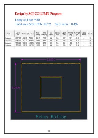
- 68. 68 Design by SCI COLUMN Program: Using 254 bar ᶲ 22 Total area Steel=966 Cm^2 Steel ratio = 0.4%
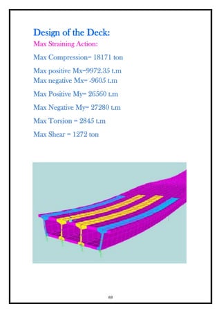
- 69. 69 Design of the Deck: Max Straining Action: Max Compression= 18171 ton Max positive Mx=9972.35 t.m Max negative Mx= -9605 t.m Max Positive My= 26560 t.m Max Negative My= 27280 t.m Max Torsion = 2845 t.m Max Shear = 1272 ton
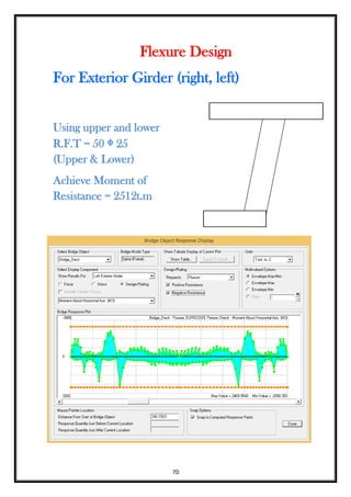
- 70. 70 Flexure Design For Exterior Girder (right, left) Using upper and lower R.F.T = 50 ᶲ 25 (Upper & Lower) Achieve Moment of Resistance = 2512t.m
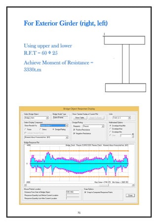
- 71. 71 For Exterior Girder (right, left) Using upper and lower R.F.T = 60 ᶲ 25 Achieve Moment of Resistance = 3330t.m
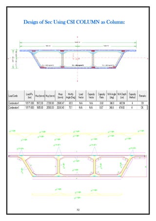
- 72. 72 Design of Sec Using CSI COLUMN as Column:
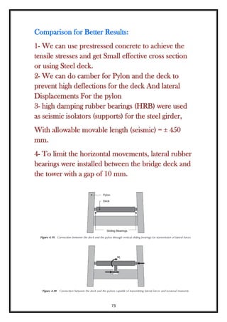
- 73. 73 Comparison for Better Results: 1- We can use prestressed concrete to achieve the tensile stresses and get Small effective cross section or using Steel deck. 2- We can do camber for Pylon and the deck to prevent high deflections for the deck And lateral Displacements For the pylon 3- high damping rubber bearings (HRB) were used as seismic isolators (supports) for the steel girder, With allowable movable length (seismic) = ± 450 mm. 4- To limit the horizontal movements, lateral rubber bearings were installed between the bridge deck and the tower with a gap of 10 mm.
- 74. 74