catalog44
- 1. 02.2014 www.keddco.com SARNIA | EDMONTON | HOUSTON
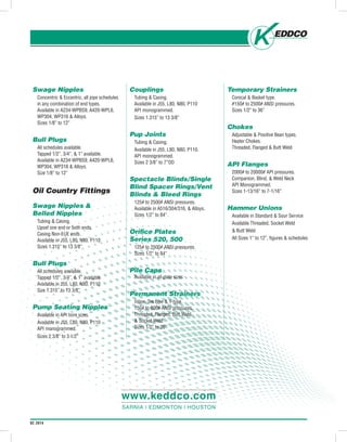
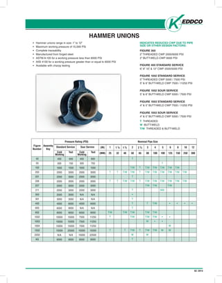
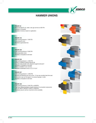
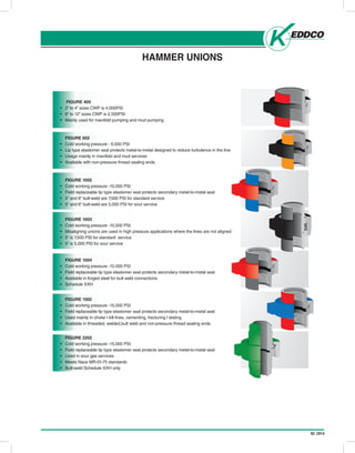
- 2. 02.2014 Swage Nipples Concentric & Eccentric, all pipe schedules in any combination of end types. Available in A234-WPBS9, A420-WPL6, WP304, WP316 & Alloys. Sizes 1/8” to 12” Bull Plugs All schedules available. Tapped 1/2”, 3/4”, & 1” available. Available in A234-WPBS9, A420-WPL6, WP304, WP316 & Alloys. Size 1/8” to 12” Oil Country Fittings Swage Nipples & Belled Nipples Tubing & Casing. Upset one end or both ends. Casing Non-EUE ends. Available in J55, L80, N80, P110 Sizes 1.315” to 13 3/8” Bull Plugs All schedules available. Tapped 1/2”, 3/4”, & 1” available. Available in J55, L80, N80, P110 Size 1.315” to 13 3/8” Pump Seating Nipples Available in API bore sizes. Available in J55, L80, N80, P110 API monogrammed. Sizes 2 3/8” to 3 1/2” Couplings Tubing & Casing. Available in J55, L80, N80, P110 API monogrammed. Sizes 1.315” to 13 3/8” Pup Joints Tubing & Casing. Available in J55, L80, N80, P110. API monogrammed. Sizes 2 3/8” to 7”OD Spectacle Blinds/Single Blind Spacer Rings/Vent Blinds & Bleed Rings 125# to 2500# ANSI pressures. Available in A516/304/316, & Alloys. Sizes 1/2” to 84”. Orifice Plates Series 520, 500 125# to 2500# ANSI pressures. Sizes 1/2” to 84” Pile Caps Available in all plate sizes Permanent Strainers Inline, Tee type & Y-type. 150# to 600# ANSI pressures. Threaded, Flanged, Butt Weld & Socket Weld Sizes 1/2” to 36” Temporary Strainers Conical & Basket type. #150# to 2500# ANSI pressures. Sizes 1/2” to 36” Chokes Adjustable & Positive Bean types. Heater Chokes. Threaded, Flanged & Butt Weld API Flanges 2000# to 20000# API pressures. Companion, Blind, & Weld Neck API Monogrammed. Sizes 1-13/16” to 7-1/16” Hammer Unions Available in Standard & Sour Service Available Threaded, Socket Weld & Butt Weld All Sizes 1” to 12”, figures & schedules www.keddco.com SARNIA | EDMONTON | HOUSTON
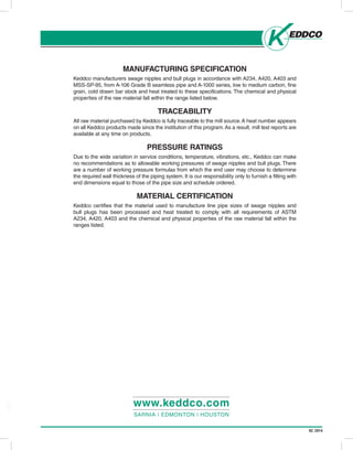
- 3. 02.2014 MANUFACTURING SPECIFICATION Keddco manufacturers swage nipples and bull plugs in accordance with A234, A420, A403 and MSS-SP-95, from A-106 Grade B seamless pipe and A-1000 series, low to medium carbon, fine grain, cold drawn bar stock and heat treated to these specifications. The chemical and physical properties of the raw material fall within the range listed below. TRACEABILITY All raw material purchased by Keddco is fully traceable to the mill source.A heat number appears on all Keddco products made since the institution of this program.As a result, mill test reports are available at any time on products. PRESSURE RATINGS Due to the wide variation in service conditions, temperature, vibrations, etc., Keddco can make no recommendations as to allowable working pressures of swage nipples and bull plugs. There are a number of working pressure formulas from which the end user may choose to determine the required wall thickness of the piping system. It is our responsibility only to furnish a fitting with end dimensions equal to those of the pipe size and schedule ordered. MATERIAL CERTIFICATION Keddco certifies that the material used to manufacture line pipe sizes of swage nipples and bull plugs has been processed and heat treated to comply with all requirements of ASTM A234, A420, A403 and the chemical and physical properties of the raw material fall within the ranges listed. www.keddco.com SARNIA | EDMONTON | HOUSTON
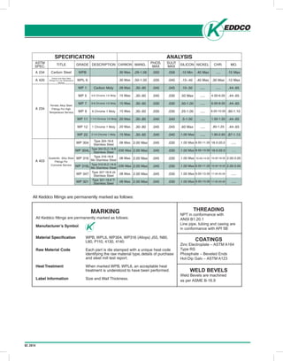
- 4. 02.2014 Head Office: P.O. Box 999, 645 Keddco Street, Sarnia, Ontario N7T 7K6 Telephone (519) 336-2960 Fax (519) 344-3181 4120 - 78 Avenue, Edmonton, Alberta T6B 3M8 Telephone (780) 438-4944 Fax (780) 435-3917 Toll Free 1-800-661-3809 www.keddco.com ISSUE-2005/10 .045 .030WP 321 Type 321-18-8 Ti Stainless Steel 2.00 Max .1.00 Max 9.00-13.00 17.00-20.00 ......08 Max. A3 FOR CARBON AND ALLOY STEEL FITTINGS FERRETIC ALLOY STEEL FITTINGS AUSTENTIC ALLOY STEEL FITTINGS SPECIFICATION ASTM SPEC. A 420 A 234 A 403 PHOS. MAX SULP. MAX .040.035 .045 .040 .030 .030 .040 .045 .040 .045 .045 .045 .045 .045 .045 .030 .030 .030 .040 .045 .040 .030 .030 .030 .030 .030 TITLE Carbon and Alloy Steel Fittings For Low Temperature Service Ferretic Alloy Steel Fittings For High Temperature Service Austenitic Alloy Steel Fittings For Corrosive Service GRADE WPL 6 WP 1 WP 5 WP 7 WP 9 WP 11 WP 12 WP 22 WP 304 WP 304L WP 316 WP 316L WP 347 DESCRIPTION Carbon Moly 4-6 Chrome 1/2 Moly 6-8 Chrome 1/2 Moly 9 Chrome 1 Moly 1 Chrome 1 Moly Type 304-18-8 Stainless Steel Type 304 ELC-18-8 Stainless Steel Type 316 ELC-18-8 Mo Stainless Steel Type 316-18-8 Mo Stainless Steel Type 347-18-8 cb Stainless Steel 1 1/4 Chrome 1/2 Moly 2 1/4 Chrome 1 Moly MANG. .50-1.35 .30-.90 .30-.60 .30-.60 .30-.60 .30-.80 .30-.80 .30-.60 2.00 Max 2.00 Max 2.00 Max 2.00 Max 2.00 Max SILICON .15-.40 .10-.50 .50 Max .50-1.00 .25-1.00 .5-1.00 .60 Max .1.00 Max .1.00 Max .1.00 Max .1.00 Max .1.00 Max .1.00 Max NICKEL .40 Max ..... ..... ..... ..... ..... ..... ..... 8.00-11.00 8.00-13.00 10.00-14.00 8.00-11.00 9.00-13.00 CHR. .30 Max ..... 4.00-6.00 6.00-8.00 8.00-10.00 1.00-1.50 .80-1.25 1.90-2.60 18.0-20.0 18.0-20.0 16.00-18.00 16.00-18.00 17.00-20.00 MO. .12 Max .44-.65 .44-.65 .44-.65 .90-1.10 .44-.65 .44-.65 .87-1.13 ..... ..... 2.00-3.00 2.00-3.00 ..... CARBON .30 Max. A 234 .058.050Carbon Steel WPB .29-1.06 .10 Min .40 Max ..... .15 Max.30 Max. .28 Max. .15 Max. .15 Max. .15 Max. .20 Max. .20 Max. .15 Max. .08 Max. .035 Max. .08 Max. .035 Max. .08 Max. ANALYSIS MARKING All Keddco fittings are permanently marked as follows: Manufacturer’s Symbol Material Specification WPB, WPL6, WP304, WP316 (Alloys) J55, N80, L80, P110, 4130, 4140 Raw Material Code Each part is die stamped with a unique heat code identifying the raw material type,details of purchase and steel mill test report. Heat Treatment When marked WPB, WPL6, an acceptable heat treatment is understood to have been performed. Label Information Size and Wall Thickness. THREADING NPT in conformance with ANSI B1.20.1 Line pipe, tubing and casing are in conformance with API 5B COATINGS Zinc Electroplate – ASTM A164 Type RS Phosphate – Beveled Ends Hot-Dip Galv – ASTM A123 WELD BEVELS Weld Bevels are machined as per ASME B-16.9 All Keddco fittings are permanently marked as follows:
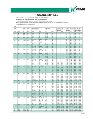
- 5. 02.2014 • Nominal Pipe size range 1/8 NPS / 6 DN – 12 NPS / 200 DN. • Choice of raw material dependant upon size and reduction. • Available standard, extra heavy, schedule 160, or double extra heavy. • End finishes available: current API threads or ANSI, beveled, square cut (for socket-weld), or grooved. • Available concentric and eccentric. SWAGE NIPPLES SIZE PIPE NPS DN IN MM API or O.D. NPS DN REDUCED TO IN MM LENGTH LB KG STANDARD WEIGHT LB KG EXTRA HEAVY WEIGHT LB KG DBL EX. & 160 WEIGHT 1/4 3/8 1/2 3/4 1 1-1/4 1-1/2 2 2-1/2 3 3-1/2 4 5 6 8 10 12 8 10 15 20 25 32 40 50 65 80 90 100 125 150 200 250 300 .540 .675 .840 1.050 1.315 1.660 1.900 2-3/8 2-7/8 3-1/2 4 4-1/2 5-9/16 6-5/8 8-5/8 10-3/4 12-3/4 15 15 20 25 33 42 48 60 73 88 100 114 140 168 219 273 324 1/8 1/8 1/4 1/8 1/4 & 3/8 1/8 1/4 & 3/8 1/2 1/8 1/4 & 3/8 1/2 & 3/4 1/4 & 3/8 1/2 & 3/4 1 1/4 & 3/8 1/2 & 3/4 1 1-1/4 1/4 & 3/8 1/2 & 3/4 1 1-1/4 1-1/2 1/2 & 3/4 1 1-1/4 1-1/2 2 1/2 & 3/4 1 1-1/4 1-1/2 2 & 2-1/2 1/2 thru 1-1/2 2 thru 3 1/2 & 3/4 1 1-1/4 & 1-1/2 2 2-1/2 3 & 3-1/2 1 thru 1-1/2 2 & 2-1/2 3 & 3-1/2 4 1 thru 1-1/2 2 & 2-1/2 3 & 3-1/2 4 5 2 thru 3 4 & 5 6 6 6 8 6 8 & 10 6 8 & 10 15 6 8 & 10 15 & 20 8 & 10 15 & 20 25 8 & 10 15 & 20 25 32 8 & 10 15 & 20 25 32 40 15 & 20 25 32 40 50 15 & 20 25 32 40 50 & 65 15 thru 40 50 thru 80 15 & 20 25 32 & 40 50 65 80 & 90 25 thru 40 50 & 65 80 & 90 100 25 thru 40 50 & 65 80 & 90 100 125 50 thru 80 100 & 125 150 2-1/4 2-1/2 2-1/2 2-3/4 2-3/4 3 3 3 3-1/2 3-1/2 3-1/2 4 4 4 4-1/2 4-1/2 4-1/2 4-1/2 6-1/2 6-1/2 6-1/2 6-1/2 6-1/2 7 7 7 7 7 8 8 8 8 8 8 8 9 9 9 9 9 9 11 11 11 11 12 12 12 12 12 13 13 13 15 18 57 63 63 70 70 76 76 76 88 88 88 102 102 102 114 114 114 114 165 165 165 165 165 178 178 178 178 178 203 203 203 203 203 203 203 229 229 229 229 229 229 279 279 279 279 305 305 305 305 305 330 330 330 381 457 2.00 2.00 2.00 3.00 3.00 3.00 3.00 4.50 4.50 4.50 4.50 5.50 5.50 7.50 7.50 7.50 7.50 7.50 11.50 11.50 11.50 11.50 17.00 17.00 17.00 17.00 17.00 29.00 29.00 29.00 48.00 75.00 .90 .90 .90 1.36 1.36 1.36 1.36 2.00 2.00 2.00 2.00 2.50 2.50 3.40 3.40 3.40 3.40 3.40 5.23 5.23 5.23 5.23 7.73 7.73 7.73 7.73 7.73 13.20 13.20 13.20 22.00 34.00 .25 .25 .33 .33 .50 .50 .50 .66 .66 .66 1.00 1.00 1.00 1.17 1.17 1.17 1.17 3.00 3.00 2.33 2.33 2.33 3.50 3.50 3.50 3.50 3.50 6.00 6.00 6.00 6.00 6.00 7.50 7.50 10.00 10.00 10.00 10.00 10.00 10.00 17.00 17.00 17.00 17.00 25.00 25.00 25.00 25.00 25.00 44.00 44.00 44.00 66.00 98.00 .11 .11 .15 .15 .23 .23 .23 .30 .30 .30 .45 .45 .45 .53 .53 .53 .53 1.36 1.36 1.06 1.06 1.06 1.60 1.60 1.60 1.60 1.60 2.73 2.73 2.73 2.73 2.73 3.40 3.40 4.50 4.50 4.50 4.50 4.50 4.50 7.73 7.73 7.73 7.73 11.40 11.40 11.40 11.40 11.40 20.00 20.00 30.00 45.00 .25 .38 .38 .50 .50 .75 .75 .75 1.00 1.00 1.00 1.50 1.50 1.50 2.00 2.00 2.00 2.00 4.25 4.25 4.25 4.25 4.25 8.00 8.00 8.00 8.00 8.00 11.00 11.00 11.00 11.00 11.00 13.50 13.50 18.00 18.00 18.00 18.00 18.00 18.00 33.00 33.00 33.00 33.00 46.00 46.00 46.00 46.00 46.00 78.00 78.00 78.00 130.00 180.00 .11 .17 .17 .23 .23 .34 .34 .34 .45 .45 .45 .68 .68 .68 .91 .91 .91 .91 1.93 1.93 1.93 1.93 1.93 3.64 3.64 3.64 3.64 3.64 5.00 5.00 5.00 5.00 5.00 6.14 6.14 8.20 8.20 8.20 8.20 8.20 8.20 15.00 15.00 15.00 15.00 21.00 21.00 21.00 21.00 21.00 36.00 36.00 36.00 59.00 85.00
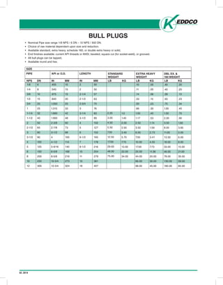
- 6. 02.2014 • Nominal Pipe size range 1/8 NPS / 6 DN – 12 NPS / 300 DN. • Choice of raw material dependant upon size and reduction. • Available standard, extra heavy, schedule 160, or double extra heavy or solid. • End finishes available: current API threads or ANSI, beveled, square cut (for socket-weld), or grooved. • All bull plugs can be tapped. • Available round and hex. BULL PLUGS SIZE PIPE NPS DN IN MM API or O.D. IN MM LENGTH LB KG STANDARD WEIGHT LB KG EXTRA HEAVY WEIGHT LB KG DBL EX. & 160 WEIGHT 1/8 1/4 3/8 1/2 3/4 1 1-1/4 1-1/2 2 2-1/2 3 3-1/2 4 5 6 8 10 12 6 8 10 15 20 25 32 40 50 65 80 90 100 125 150 200 250 300 .405 .540 .675 .840 1.050 1.315 1.660 1.900 2-3/8 2-7/8 3-1/2 4 4-1/2 5-9/16 6-5/8 8-5/8 10-3/4 12-3/4 10 15 15 20 25 33 42 48 60 73 88 100 114 140 168 219 273 324 2 2 2-1/4 2-1/2 2-3/4 3 3-1/4 3-1/2 4 5 6 6-1/2 7 8-1/2 10 11 15 18 50 50 57 63 70 76 83 89 102 127 152 165 178 216 254 279 381 457 2.25 3.00 4.50 5.50 7.50 12.50 17.00 29.00 48.00 75.00 1.0 1.40 2.00 2.50 3.40 5.70 7.70 13.00 22.00 34.00 .10 .11 .14 .33 .50 .66 1.00 1.17 2.50 3.50 6.00 7.50 10.00 17.00 25.00 44.00 66.00 98.00 .05 .05 .06 .15 .23 .30 .45 .53 1.14 1.59 2.73 3.41 4.55 7.73 11.36 20.00 30.00 45.00 .40 .40 .28 .50 .75 1.00 1.50 2.00 3.50 8.00 11.00 13.50 18.00 33.00 46.00 78.00 130.00 180.00 .20 .20 .13 .23 .34 .45 .70 .90 1.60 3.60 5.00 6.00 8.00 15.00 21.00 35.00 59.00 85.00
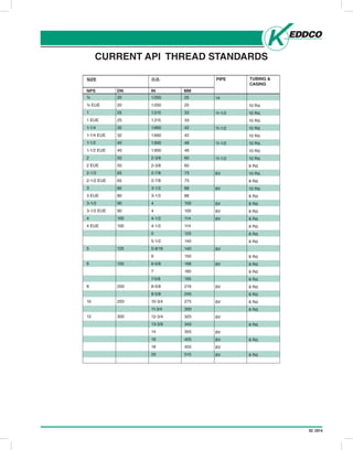
- 7. 02.2014 CURRENT API THREAD STANDARDS NPS DN SIZE IN MM O.D. PIPE TUBING & CASING ¾ ¾ EUE 1 1 EUE 1-1/4 1-1/4 EUE 1-1/2 1-1/2 EUE 2 2 EUE 2-1/2 2-1/2 EUE 3 3 EUE 3-1/2 3-1/2 EUE 4 4 EUE 5 6 8 10 12 20 20 25 25 32 32 40 40 50 50 65 65 80 80 90 90 100 100 125 150 200 250 300 1.050 1.050 1.315 1.315 1.660 1.660 1.900 1.900 2-3/8 2-3/8 2-7/8 2-7/8 3-1/2 3-1/2 4 4 4-1/2 4-1/2 5 5-1/2 5-9/16 6 6-5/8 7 7-5/8 8-5/8 9-5/8 10-3/4 11-3/4 12-3/4 13-3/8 14 16 18 20 25 25 33 33 42 42 48 48 60 60 73 73 88 88 100 100 114 114 125 140 140 150 168 180 195 219 245 275 300 325 340 355 405 455 510 14 11-1/2 11-1/2 11-1/2 11-1/2 8V 8V 8V 8V 8V 8V 8V 8V 8V 8V 8V 8V 8V 8V 10 Rd. 10 Rd. 10 Rd. 10 Rd. 10 Rd. 10 Rd. 10 Rd. 10 Rd. 8 Rd. 10 Rd. 8 Rd. 10 Rd. 8 Rd. 8 Rd. 8 Rd. 8 Rd. 8 Rd. 8 Rd. 8 Rd. 8 Rd. 8 Rd. 8 Rd. 8 Rd. 8 Rd. 8 Rd. 8 Rd. 8 Rd. 8 Rd. 8 Rd. 8 Rd.
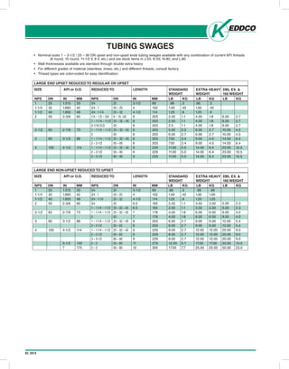
- 8. 02.2014 • Nominal sizes 1 – 3-1/2 / 25 – 90 DN upset and non-upset ends tubing swages available with any combination of current API threads (8 round, 10 round, 11-1/2 V, 8 V, etc.) and are stock items in J-55, K-55, N-80, and L-80 • Wall thicknesses available are standard through double extra heavy • For different grades of material (stainless, brass, etc.) and different threads, consult factory • Thread types are color-coded for easy identification. TUBING SWAGES LARGE END UPSET REDUCED TO REGULAR OR UPSET SIZE NPS DN IN MM API or O.D. NPS DN REDUCED TO IN MM LENGTH LB KG STANDARD WEIGHT LB KG EXTRA HEAVY WEIGHT LB KG DBL EX. & 160 WEIGHT 1 1-1/4 1-1/2 2 2-1/2 3 4 25 32 40 50 65 80 100 1.315 1.660 1.900 2-3/8 2-7/8 3-1/2 4-1/2 33 42 48 60 73 88 114 3/4 3/4 - 1 3/4 - 1-1/4 1/4 – 1/2 – 3/4 1 – 1-1/4 – 1-1/2 2-1/16 O.D. 1 – 1-1/4 – 1-1/2 2 1 – 1-1/4 – 1-1/2 2 – 2-1/2 1 – 1-1/4 – 1-1/2 2 – 2-1/2 3 – 3-1/2 20 20 – 25 20 – 32 8 – 15 –20 25 – 32 – 40 52 25 – 32 – 40 50 25 – 32 – 40 50 – 65 25 – 32 – 40 50 – 65 80 – 90 3-1/2 4 4-1/2 8 8 8 8 8 8 8 9 9 9 89 102 114 203 203 203 203 203 203 203 229 229 229 .66 1.00 1.25 2.50 2.50 2.5 5.00 6.00 7.50 7.50 11.00 11.00 11.00 .3 .45 .6 1.1 1.1 1.1 2.2 2.7 3.4 3.4 5.0 5.0 5.0 .66 1.00 1.25 4.00 4.00 4.00 6.00 6.00 9.00 9.00 14.00 14.00 14.00 .3 .45 .6 1.8 1.8 1.8 2.7 2.7 4.0 4.0 6.4 6.4 6.4 6.00 6.00 6.00 10.00 10.00 14.00 14.00 23.00 23.00 23.00 2.7 2.7 2.7 4.5 4.5 6.4 6.4 10.5 10.5 10.5 LARGE END NON-UPSET REDUCED TO UPSET SIZE NPS DN IN MM API or O.D. NPS DN REDUCED TO IN MM LENGTH LB KG STANDARD WEIGHT LB KG EXTRA HEAVY WEIGHT LB KG DBL EX. & 160 WEIGHT 1 1-1/4 1-1/2 2 2-1/2 3 4 25 32 40 50 65 80 100 1.315 1.660 1.900 2-3/8 2-7/8 3-1/2 4-1/2 5-1/2 7 33 42 48 60 73 88 114 140 175 3/4 3/4 - 1 3/4 - 1-1/4 3/4 1 – 1-1/4 – 1-1/2 1 – 1-1/4 – 1-1/2 2 1 – 1-1/4 – 1-1/2 2 – 2-1/2 1 – 1-1/4 – 1-1/2 2 – 2-1/2 3 – 3-1/2 2 – 3 2 – 3 20 20 – 25 20 – 32 20 25 – 32 – 40 25 – 32 – 40 50 25 – 32 – 40 50 – 65 25 – 32 – 40 50 – 65 80 – 90 50 – 80 50 – 80 3-1/2 4 4-1/2 6.5 6.5 7 7 8 8 9 9 9 11 12 89 102 114 165 165 178 178 203 203 229 229 229 279 305 .66 1.00 1.25 2.50 2.50 4.00 4.00 6.00 6.00 8.00 8.00 8.00 12.50 17.00 .3 .45 .6 1.1 1.1 1.8 1.8 2.7 2.7 2.7 2.7 2.7 5.7 7.7 .66 1.00 1.25 3.50 3.50 6.00 6.00 9.00 9.00 12.00 12.00 12.00 17.00 25.00 .66 1.00 1.25 3.50 3.50 6.00 6.00 9.00 9.00 12.00 12.00 12.00 17.00 25.00 5.00 5.00 9.00 9.00 12.00 12.00 20.00 20.00 20.00 33.00 50.00 2.3 2.3 4.0 4.0 5.4 5.4 9.0 9.0 9.0 15.0 23.0
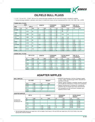
- 9. 02.2014 • 4-1/2” / 114 mm O.D. – 13-3/8” / 340 mm O.D. casing bull plugs available with all current API threads or beveled for welding • Casing bull plugs available in standard, extra heavy or double extra heavy, and are manufactured from J-55, K-55, N-80, L-80, or WPB OILFIELD BULL PLUGS TUBING BULL PLUGS PIPE NPS DN IN MM API or IN MM LB KG LENGTH LB KG STANDARD WEIGHT LB KG EXTRA HEAVY WEIGHT DBL EX. & 160 WEIGHT 3/4 EUE 1 1 EUE 1-1/4 1-1/4 EUE 1-1/2 1-1/2 EUE 2 2 EUE 2-1/2 2-1/2 EUE 3 3 EUE 4 4 EUE 20 25 25 32 32 40 40 50 50 65 65 80 80 10 10 1.315 1.660 1.900 2-3/8 2-7/8 3-1/2 4-1/2 35 40 50 60 75 90 114 3 3 3 3-1/4 3-1/4 3-1/2 3-1/2 4 5 5 5-1/2 6 6-1/2 7 7 76 76 76 83 83 89 89 102 127 127 140 153 165 178 178 1.50 1.50 1.50 1.50 1.50 1.50 2.00 2.00 3.50 3.00 4.25 4.50 10.00 20.00 20.00 .68 .68 .68 .68 .68 .68 .9 .9 1.6 1.40 1.9 1.9 4.5 9 10 .50 .66 1.00 1.06 2.25 3.00 4.00 3.50 6.00 5.00 15.00 25.00 27.00 .23 .3 .45 .48 1.0 1.4 1.8 1.6 2.7 2.3 7.0 11.4 12.3 4.25 9.00 8.00 14.00 11.00 25.00 30.00 33.00 1.9 4.0 3.6 6.4 5.0 11.4 13.6 15 SIZE CASING BULL PLUGS IN MM API or O.D. IN MM LB KG LENGTH LB KG STANDARD WEIGHT LB KG EXTRA HEAVY WEIGHT DBL EX. & 160 WEIGHT 4-1/2 5 5-1/2 6-5/8 7 7-5/8 8-5/8 113 127 140 168 175 194 219 7 8 8-1/2 10 10 11 11 178 203 216 254 254 279 279 7.50 9.50 12.50 17.00 17.00 24.00 29.00 3.4 4.3 5.7 7.7 7.7 11.0 13.0 10.00 15.00 17.00 25.00 25.00 32.00 44.00 4.5 6.8 7.7 11.4 11.4 14.5 20.0 18.00 24.00 33.00 46.00 50.00 53.00 78.00 8.2 11.0 15.0 21.0 23.0 24.0 35.0 • KEDDCO manufactures a full line of adapter nipples in sizes 1 NPS / 25 DN through 8 NPS / 200 DN from seamless A106 pipe • Adapter nipples available in threaded, beveled, grooved and virtually all combinations of these end connections • Nipples manufactured in schedule 40, schedule 80, schedule 160 and double extra heavy wall thickness • Full traceability and mill certification available upon request at time of order ADAPTER NIPPLES BELL NIPPLES NPS MM O.D. SIZE IN MM WEIGHT 4-1/2 5-1/2 7 8-5/8 9-5/8 113 140 175 219 245 4.5 9 13.2 15 2 4 6 7 ADAPTER NIPPLES IN MM API or IN MM LB KG LENGTH LB KG STANDARD WEIGHT EXTRA HEAVY WEIGHT 3/4 1 1-1/4 1-1/2 2 2-1/2 3 20 25 32 40 50 65 80 3.65 5.79 7.58 5.48 8.68 11.35 4 5 6 8 10 12 100 125 150 200 250 300 10.79 14.62 18.97 28.55 40.48 49.56 16.14 21.88 28.38 42.74 60.59 74.18 SEAMLESS SCHEDULE 40 • Std bull plugs listed above are made from J-55 (or better). Such items in XH and XXH are made from J-55, K-55, N-80 or the most appropriate material available.
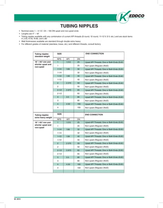
- 10. 02.2014 TUBING NIPPLES • Nominal sizes 1 – 4-1/2 / 25 – 100 DN upset and non-upset ends • Lengths are 4” – 18” • Tubing nipples available with any combination of current API threads (8 round, 10 round, 11-1/2 V, 8 V, etc.) and are stock items in J-55, K-55, N-80, and L-80 • Wall thicknesses available are standard through double extra heavy • For different grades of material (stainless, brass, etc.) and different threads, consult factory NPS DN SIZE END CONNECTIONTubing nipples standard weight 18” / 457 mm and shorter upset and non-upset Tubing nipples extra heavy weight 18” / 457 mm and shorter upset and non-upset 1 1 1-1/4 1-1/4 1-1/2 1-1/2 2 2 2-1/2 2-1/2 3 3 4 4 1 1 1-1/4 1-1/4 1-1/2 1-1/2 2 2 2-1/2 2-1/2 3 3 4 4 25 25 32 32 40 40 50 50 65 65 80 80 100 100 25 25 32 32 40 40 50 50 65 65 80 80 100 100 Upset API Threads: One or Both Ends (EUE) Non-upset (Regular) (NUE) Upset API Threads: One or Both Ends (EUE) Non-upset (Regular) (NUE) Upset API Threads: One or Both Ends (EUE) Non-upset (Regular) (NUE) Upset API Threads: One or Both Ends (EUE) Non-upset (Regular) (NUE) Upset API Threads: One or Both Ends (EUE) Non-upset (Regular) (NUE) Upset API Threads: One or Both Ends (EUE) Non-upset (Regular) (NUE) Upset API Threads: One or Both Ends (EUE) Non-upset (Regular) (NUE) END CONNECTION Upset API Threads: One or Both Ends (EUE) Non-upset (Regular) (NUE) Upset API Threads: One or Both Ends (EUE) Non-upset (Regular) (NUE) Upset API Threads: One or Both Ends (EUE) Non-upset (Regular) (NUE) Upset API Threads: One or Both Ends (EUE) Non-upset (Regular) (NUE) Upset API Threads: One or Both Ends (EUE) Non-upset (Regular) (NUE) Upset API Threads: One or Both Ends (EUE) Non-upset (Regular) (NUE) Upset API Threads: One or Both Ends (EUE) Non-upset (Regular) (NUE) NPS DN SIZE API 1.315 1.66 1.99 2.375 2.875 3.5 4.50 1.315 1.66 1.99 2.375 2.875 3.5 4.50 API
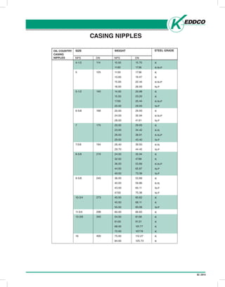
- 11. 02.2014 CASING NIPPLES NPS DN SIZE STEEL GRADEOIL COUNTRY CASING NIPPLES 4-1/2 5 5-1/2 6-5/8 7 7-5/8 8-5/8 9-5/8 10-3/4 11-3/4 13-3/8 16 114 125 140 168 175 194 219 245 273 298 340 400 K K-N-P K K K-N-P N-P K K K-N-P N-P K K-N-P N-P K K-N K-N-P N-P K-N N-P K K K-N-P N-P N-P K K-N N-P N-P K K N-P K K K K K K K NPS DN WEIGHT 10.50 11.60 11.50 13.00 15.00 18.00 14.00 15.50 17.00 20.00 20.00 24.00 28.00 20.00 23.00 26.00 29.00 26.40 29.70 24.00 32.00 36.00 44.00 49.00 36.00 40.00 43.50 47.00 40.50 45.50 55.50 60.00 54.50 61.00 68.00 72.00 75.00 84.00 15.70 17.36 17.36 19.47 22.44 26.93 20.98 23.20 25.44 29.93 29.93 35.94 41.91 29.93 34.42 38.91 43.40 39.50 44.45 35.94 47.88 53.89 65.87 73.36 53.89 59.86 65.11 70.36 60.62 68.11 83.06 89.83 81.58 91.31 101.77 107.78 112.27 125.73
- 12. 02.2014
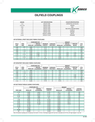
- 13. 02.2014 OILFIELD COUPLINGS GRADE H-40 J-55, K-55 N-80 L-80 C-90 C-95 P110 Q-125 5CT SPECIFICATION GROUP ONE GROUP ONE GROUP ONE GROUP TWO GROUP TWO GROUP TWO GROUP THREE GROUP FOUR COLOR SPECIFICATION UNPAINTED OR BLACK GREEN RED RED WITH BROWN BAND PURPLE BROWN WHITE ORANGE CPLG SIZE REGULAR SPECIAL CLEARANCE REGULAR SPECIAL BEVEL WEIGHT CTN QTY 1.050 1.315 1.660 1.900 2 3/8 2 7/8 3 1/2 4 4 1/2 3/4 1 1 1/4 1 1/2 2 2 1/2 3 3 1/2 4 1.660 1.990 2.200 2.500 3.063 3.668 4.500 5.000 5.563 ----- ----- ----- ----- 2.910 3.460 4.180 ----- ----- 3 1/4 3 1/2 3 3/4 3 7/8 4 7/8 5 1/4 5 3/4 6 6 1/4 10 10 10 10 8 8 8 8 8 0.84 1.26 1.49 1.85 3.42 5.29 9.02 10.62 13.31 ----- ----- ----- ----- 2.38 3.45 5.22 ----- ----- ----- ----- ----- ----- 3.29 5.07 8.55 ----- ----- 1500 1200 800 600 1144 792 448 245 210 COUPLING O.D. PIPE SIZE MINIMUM LENGTH THREADS PER INCH SPECIAL CLEARANCE API EXTERNAL UPSET END (EUE) TUBING COUPLINGS CPLG SIZE REGULAR SPECIAL CLEARANCE REGULAR SPECIAL BEVEL WEIGHT CTN QTY 1.315 1.660 1.900 2 3/8 2 7/8 3 1/2 4 4 1/2 1 1 1/4 1 1/2 2 2 1/2 3 3 1/2 4 1.660 2.054 2.200 2.875 3.500 4.250 4.750 5.200 ----- ----- ----- ----- ----- ----- ----- ----- 3 1/4 3 1/2 3 3/4 4 1/4 5 1/8 5 5/8 5 3/4 6 1/8 10 10 10 10 10 10 8 8 0.84 1.26 1.25 2.82 5.15 8.17 9.57 10.76 ----- ----- ----- ----- ----- ----- ----- ----- ----- ----- ----- 2.69 4.90 7.73 ----- ----- 1500 1000 800 1144 792 256 360 235 COUPLING O.D. PIPE SIZE MINIMUM LENGTH THREADS PER INCH SPECIAL CLEARANCE API NONUPSET END (EUE) TUBING COUPLINGS REGULAR SPECIAL CLEARANCE REGULAR WEIGHT CARTON QUANTITY 4 1/2 5 5 1/2 6 5/8 7 7 5/8 8 5/8 9 5/8 10 3/4 11 3/4 13 3/8 16 18 5/8 20 5.000 5.563 6.050 7.390 7.656 8.500 9.625 10.625 11.750 12.750 14.375 17.000 20.000 21.000 4.875 5.375 5.875 7.000 7.375 8.125 9.125 10.125 11.250 ----- ----- ----- ----- ----- 8 7/8 9 1/8 9 1/4 9 5/8 10 10 3/8 10 5/8 10 5/8 10 5/8 10 5/8 10 5/8 10 5/8 10 5/8 10 5/8 10.11 12.99 14.14 24.46 23.22 34.84 45.94 50.99 56.68 61.74 69.95 87.56 138.03 110.33 7.67 8.81 9.84 12.44 13.82 20.45 23.77 26.47 29.49 ----- ----- ----- ----- ----- 196 196 136 100 84 64 52 40 45 40 25 20 12 8 COUPLING O.D. PIPE SIZE MINIMUM LENGTH SPECIAL CLEARANCE API BUTTRESS THREAD CASING COUPLINGS Note: All buttress couplings are 5 threads per inch with 4 1/2 thru 13 3/8 taper tapped 3/4” per foot on diameter and 16” thru 20” taper tapped 1” per foot.
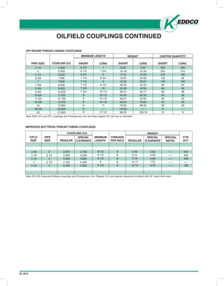
- 14. 02.2014 OILFIELD COUPLINGS CONTINUED API ROUND THREAD CASING COUPLINGS COUPLING O.D. WEIGHT 4 1/2 5 5 1/2 6 5/8 7 7 5/8 8 5/8 9 5/8 10 3/4 11 3/4 13 3/8 16 18 5/8 20 5.000 5.563 6.050 7.390 7.656 8.500 9.625 10.625 11.750 12.750 14.375 17.000 20.000 21.000 6 1/4 6 1/2 6 3/4 7 1/4 7 1/4 7 1/2 7 3/4 7 3/4 8 8 8 9 9 9 PIPE SIZE MINIMUM LENGTH CARTON QUANTITY SHORT LONG SHORT LONG SHORT LONG 7 7 3/4 8 8 3/4 9 9 1/4 10 10 1/2 10 1/2 10 1/2 10 1/2 11 ----- 11 1/2 8.05 10.18 11.44 19.97 18.34 26.93 35.58 39.51 45.53 49.61 56.23 79.00 118.94 98.25 9.07 12.56 14.03 24.82 23.67 34.23 47.48 55.77 62.02 67.39 76.63 96.55 ----- 126.74 294 252 216 120 120 80 60 50 45 40 25 20 8 8 294 210 180 92 100 64 60 36 36 40 20 20 ----- 8 Note: Both LTC and STC couplings are 8 threads per inch and taper tapped 3/4” per foot on diameter CPLG SIZE REGULAR SPECIAL CLEARANCE REGULAR SPECIAL BEVEL WEIGHT CTN QTY 2 3/8 2 7/8 3 1/2 4 4 1/2 2 2 1/2 3 3 1/2 4 2.875 3.500 4.250 4.750 5.200 2.700 3.220 3.865 4.400 4.920 8 1/2 8 1/2 8 1/2 9 9 1/2 8 8 8 8 8 5.46 8.14 11.74 14.17 15.72 3.62 4.59 5.83 7.75 9.73 ----- ----- ----- ----- ----- 644 400 248 ----- 196 COUPLING O.D. PIPE SIZE MINIMUM LENGTH THREADS PER INCH SPECIAL CLEARANCE IMPROVED BUTTRESS THREAD TUBING COUPLINGS Note: All USS Improved Buttress couplings are 8 threads per inch. Regular O.D. and special clearance furnished with 20° bevel both ends.
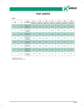
- 15. 02.2014 2 ft.End ConnectionsNPS 3 ft. 4 ft. 6 ft. 8 ft. 10 ft. 12 ft. UPSET Perforation Only - Upset Standard Performations 3/8” hole. PUP JOINTS Weight EachWeight EachWeight EachWeight EachWeight EachWeight EachWeight Each 2” 2” 2” 2 1/2” 2 1/2” 2 1/2” 3” 3” Upset A.P.I. Thds. One or Both Ends Non-upset (Regular) Integral Joint Box & Pin Upset A.P.I. Thds. One or Both Ends Non-upset (Regular) Integral Joint Box & Pin Upset A.P.I. Thds. One or Both Ends Non-upset (Regular) 8 3/4 9 9 12 1/2 12 1/2 12 1/2 17 1/2 17 1/2 13 1/4 13 13 1/4 18 1/2 18 1/2 18 1/2 26 1/2 26 1/2 17 3/4 18 18 25 1/2 24 1/2 25 1/2 35 1/4 35 26 1/2 26 1/2 26 1/2 38 37 38 52 3/4 53 35 1/2 35 1/2 35 1/2 50 1/4 49 50 1/4 70 1/4 70 44 1/4 44 1/4 44 1/4 62 1/2 61 1/2 62 1/2 88 88 52 1/2 53 53 76 74 76 105 1/2 105 API 2 3/8” 2 3/8” 2 3/8” 2 7/8” 2 7/8” 2 7/8” 3 1/2” 3 1/2”
- 16. 16 01.2014
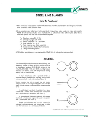
- 17. 02.2014 STEEL LINE BLANKS Head Office: P.O. Box 999, 645 Keddco Street, Sarnia, Ontario N7T 7K6 Telephone (519) 336-2960 Fax (519) 344-3181 4120 - 78 Avenue, Edmonton, Alberta T6B 3M8 Telephone (780) 438-4944 Fax (780) 435-3917 Toll Free 1-800-661-3809 www .keddco.com MFG. LTD. ISSUE-2005/10 C2 Steel Line Blanks Note To Purchaser 1.If the purchaser needs a steel line blank that deviates from this standard, the deviating requirements shall be stated in the puchase order. 2.If no exceptions are to be taken to this standard, the purchase order need only make reference to ASME B16.48 and specify the items marked with an asterisk (*) in the following list. Other items listed are options that may also be specified if required. *a. Size (see pages C4 - C17). *b. Class (see pages C4 - C17). *c. Facing (Standard 125 - 250 RMS). *d. Style (see Fig. 1, 2 or 3). *e. Plate material (see Table page C3). f. Inside diameter (if other than standard). g. Lifting or handling device. 3.All Keddco spec blinds are manufactured to ASME B16.48 unless otherwise specified. GENERAL FIG. 1 FIG. 2 FIG. 3 This standard provides dimensions for operating line blanks (or "blinds") in sizes NPS 1/2 through NPS 24 for installation between ANSI B16.5 flanges in the 150,300, 600, 900, 1500, and 2500 pound pressure classes. Line blanks used only for pressure testing are not part of this standard. A Figure 8 blank (also called a spectacle blind) is a pressure retaining plate with one solid end and one open end connected with a web or tie bar (see Figure 1) Keddco reserves the right to supply the web design (integral, double tie-bar, single wedge) that best suits the use of the raw material in the construction of the spectable blind.. A paddle blank is similar to the solid end of a figure 8 blank (with a handle) and is generally used in conjuction with a paddle spacer in large sizes (see Figure 2). A paddle spacer is similar to the open end figure 8 blank (with a handle) and is generally used in conjuction with a paddle blank (see Figure 3). Paddle spacer handles shall have one 1/2 inch (13 millimeter) minimum diameter hole located near the outer end. This hole serves as a remote visual indicator. CAUTION: Paddle blanks shall not be supplied with indicator or bolt holes.
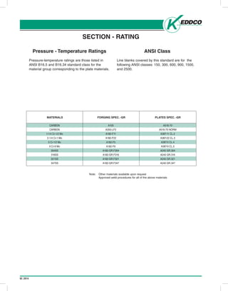
- 18. 02.2014 Head Office: P.O. Box 999, 645 Keddco Street, Sarnia, Ontario N7T 7K6 Telephone (519) 336-2960 Fax (519) 344-3181 4120 - 78 Avenue, Edmonton, Alberta T6B 3M8 Telephone (780) 438-4944 Fax (780) 435-3917 Toll Free 1-800-661-3809 www.keddco.com MFG. LTD. ISSUE-2005 SECTION - RATINGS Pressure - Temperature Ratings Pressure-temperature ratings are those listed in ANSI B16.5 and B16.34 standard class for the material group corresponding to the plate materials. ANSI Class Line blanks covered by this standard are for the following ANSI classes: 150, 300, 600, 900, 1500, and 2500. C3 FORGING PLATES MATERIALS SPEC.-GR SPEC.-GR CARBON A105 A516-70 CARBON A350-LF2 A516-70 NORM 1-1/4 Cr-1/2 Mo A182-F11 A387-11 CL.2 2-1/4 Cr-1 Mo A182-F22 A387-22 CL.3 5 Cr-1/2 Mo A182-F5 A387-5 CL.4 9 Cr-9 Mo A182-F9 A387-9 CL.5 304SS A182-GR.F304 A240 GR.304 316SS A182-GR.F316 A240 GR.316 321SS A182-GR.F321 A240 GR.321 347SS A182-GR.F347 A240 GR.347 NOTE: - Other materials available upon request - Approved weld procedures for all of the above materials SECTION - RATING Note: Other materials available upon request Approved weld procedures for all of the above materials MATERIALS CARBON CARBON 1-1/4 Cr-1/2 Mo 2-1/4 Cr-1 Mo 5 Cr-1/2 Mo 9 Cr-9 Mo 304SS 316SS 321SS 347SS FORGING SPEC. -GR PLATES SPEC. -GR A105 A350-LF2 A182-F11 A182-F22 A182-F5 A182-F9 A182-GR.F304 A182-GR.F316 A182-GR.F321 A182-GR.F347 A516-70 A516-70 NORM A387-11 CL.2 A387-22 CL.3 A387-5 CL.4 A387-9 CL.5 A240 GR.304 A240 GR.316 A240 GR.321 A240 GR.347
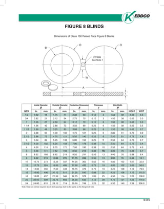
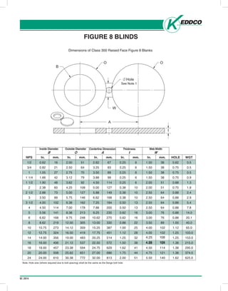
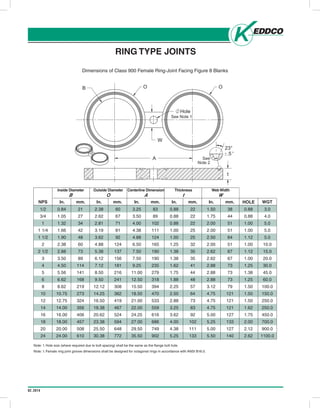
- 19. 02.2014 Head Office: P.O. Box 999, 645 Keddco Street, Sarnia, Ontario N7T 7K6 Telephone (519) 336-2960 Fax (519) 344-3181 4120 - 78 Avenue, Edmonton, Alberta T6B 3M8 Telephone (780) 438-4944 Fax (780) 435-3917 Toll Free 1-800-661-3809 www.keddco.com MFG. LTD. ISSUE-2005/10 FIGURE 8 BLINDS Dimensions of Class 150 Raised Face Figure 8 Blanks C4 NPS In. mm. In. mm. In. mm. In. mm. In. mm. HOLE WGT 1/2 0.62 16 1.75 44 2.38 60 0.12 3 1.50 38 0.62 0.3 3/4 0.82 21 2.12 54 2.75 70 0.12 3 1.50 38 0.62 0.3 1 1.05 27 2.50 64 3.12 79 0.12 6 1.50 38 0.62 0.3 1 1/4 1.66 42 2.88 73 3.50 89 0.25 6 1.50 38 0.62 0.5 1 1/2 1.90 48 3.25 83 3.88 99 0.25 6 1.50 38 0.62 0.7 2 2.38 60 4.00 102 4.75 121 0.25 6 2.00 51 0.75 0.9 2 1/2 2.88 73 4.75 121 5.50 140 0.25 6 2.00 51 0.75 1.8 3 3.50 89 5.25 133 6.00 152 0.25 10 2.50 64 0.75 2.7 3 1/2 4.00 102 6.25 159 7.00 178 0.38 10 2.50 64 0.75 3.4 4 4.50 114 6.75 171 7.50 190 0.38 10 2.50 64 0.75 4.0 5 5.56 141 7.62 194 8.50 216 0.38 13 3.00 76 0.88 6.7 6 6.62 168 8.62 219 9.50 241 0.50 13 3.00 76 0.88 9.4 8 8.62 219 10.88 276 11.75 298 0.50 13 3.00 76 0.88 19.1 10 10.75 273 13.25 337 14.25 362 0.62 16 4.00 102 1.00 32.0 12 12.75 324 16.00 406 17.00 432 0.75 19 4.00 102 1.00 56.0 14 14.00 356 17.62 448 18.75 476 0.75 19 4.25 108 1.12 79.0 16 16.00 406 20.12 511 21.25 540 0.88 22 4.25 108 1.12 115.0 18 18.00 457 21.50 546 22.75 578 1.00 25 4.50 114 1.25 138.0 20 20.00 508 23.75 603 25.00 635 1.12 28 4.75 121 1.25 179.0 24 24.00 610 28.12 714 29.50 749 1.25 32 5.50 140 1.38 306.0 Inside Diameter B Outside Diameter O Centerline Dimension A Thickness t Web Width W NOTE: Hole size (where required due to bolt spacing) shall be the same as the flange bolt hole. FIGURE 8 BLINDS Note: Hole size (where required due to bolt spacing) shall be the same as the flange bolt hole. Inside Diameter B In. Outside Diameter O Centerline Dimension A Thickness t Web Width W mm. In. mm. In. mm. In. mm. In. mm.NPS HOLE WGT See Note 1 O O B W Hole A t Dimensions of Class 150 Raised Face Figure 8 Blanks 6 10
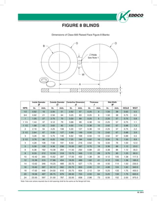
- 20. 02.2014 Head Office: P.O. Box 999, 645 Keddco Street, Sarnia, Ontario N7T 7K6 Telephone (519) 336-2960 Fax (519) 344-3181 4120 - 78 Avenue, Edmonton, Alberta T6B 3M8 Telephone (780) 438-4944 Fax (780) 435-3917 Toll Free 1-800-661-3809 www.keddco.com MFG. LTD. ISSUE-2005/10 NOTE: Hole size (where required due to bolt spacing) shall be the same as the flange bolt hole. FIGURE 8 BLINDS Dimensions of Class 300 Raised Face Figure 8 Blanks C5 NPS In. mm. In. mm. In. mm. In. mm. In. mm. HOLE WGT 1/2 0.62 16 2.00 51 2.62 67 0.25 6 1.50 38 0.62 0.5 3/4 0.82 21 2.50 64 3.25 83 0.25 6 1.50 38 0.75 0.5 1 1.05 27 2.75 70 3.50 89 0.25 6 1.50 38 0.75 0.5 1 1/4 1.66 42 3.12 79 3.88 99 0.25 6 1.50 38 0.75 0.9 1 1/2 1.90 48 3.62 92 4.50 114 0.25 6 2.00 51 0.88 1.3 2 2.38 60 4.25 108 5.00 127 0.38 10 2.00 51 0.75 1.8 2 1/2 2.88 73 5.00 127 5.88 149 0.38 10 2.50 64 0.88 2.4 3 3.50 89 5.75 146 6.62 168 0.38 10 2.50 64 0.88 2.9 3 1/2 4.00 102 6.38 162 7.25 184 0.50 13 2.50 64 0.88 5.4 4 4.50 114 7.00 178 7.88 200 0.50 13 2.50 64 0.88 7.8 5 5.56 141 8.38 213 9.25 235 0.62 16 3.00 76 0.88 14.0 6 6.62 168 9.75 248 10.62 270 0.62 16 3.00 76 0.88 20.1 8 8.62 219 12.00 305 13.00 330 0.88 22 3.50 89 1.00 40.0 10 10.75 273 14.12 359 15.25 387 1.00 25 4.00 102 1.12 65.0 12 12.75 324 16.50 419 17.75 451 1.12 28 4.00 102 1.25 103.0 14 14.00 356 19.00 483 20.25 514 1.25 32 4.75 121 1.25 153.0 16 16.00 406 21.12 537 22.50 572 1.50 38 4.88 124 1.38 215.0 18 18.00 457 23.38 594 24.75 629 1.62 41 4.50 114 1.38 295.0 20 20.00 508 25.62 651 27.00 686 1.75 44 4.75 121 1.38 374.0 24 24.00 610 30.38 772 32.00 813 2.00 51 5.50 140 1.62 625.0 Inside Diameter B Outside Diameter O Centerline Dimension A Thickness t Web Width W FIGURE 8 BLINDS Note: Hole size (where required due to bolt spacing) shall be the same as the flange bolt hole. Inside Diameter B In. Outside Diameter O Centerline Dimension A Thickness t Web Width W mm. In. mm. In. mm. In. mm. In. mm.NPS HOLE WGT See Note 1 O O B W Hole A t Dimensions of Class 300 Raised Face Figure 8 Blanks 4.25 4.25 108 108
- 21. 02.2014 Head Office: P.O. Box 999, 645 Keddco Street, Sarnia, Ontario N7T 7K6 Telephone (519) 336-2960 Fax (519) 344-3181 4120 - 78 Avenue, Edmonton, Alberta T6B 3M8 Telephone (780) 438-4944 Fax (780) 435-3917 Toll Free 1-800-661-3809 www.keddco.com MFG. LTD. ISSUE-2005/10 NOTE: Hole size (where required due to bolt spacing) shall be the same as the flange bolt hole. FIGURE 8 BLINDS Dimensions of Class 600 Raised Face Figure 8 Blanks C6 NPS In. mm. In. mm. In. mm. In. mm. In. mm. HOLE WGT 1/2 0.62 16 2.00 51 2.62 67 0.25 6 1.50 38 0.62 0.5 3/4 0.82 21 2.50 64 3.25 83 0.25 6 1.50 38 0.75 0.5 1 1.05 27 2.75 70 3.50 89 0.25 6 2.25 57 0.75 0.8 1 1/4 1.44 37 3.12 79 3.88 99 0.38 10 2.25 57 0.75 1.1 1 1/2 1.68 43 3.62 92 4.50 114 0.38 10 2.62 67 0.88 1.3 2 2.16 55 4.25 108 5.00 127 0.38 10 2.25 57 0.75 2.2 2 1/2 2.64 67 5.00 127 5.88 149 0.50 13 2.62 67 0.88 3.9 3 3.26 83 5.75 146 6.62 168 0.50 13 2.62 67 0.88 5.5 3 1/2 3.76 96 6.25 159 7.25 184 0.62 16 3.00 76 1.00 8.8 4 4.26 108 7.50 191 8.50 216 0.62 16 3.00 76 1.00 12.0 5 5.30 135 9.38 238 10.50 267 0.75 19 3.38 86 1.12 23.5 6 6.36 162 10.38 264 11.50 292 0.88 22 3.38 86 1.12 35.0 8 8.33 212 12.50 318 13.75 349 1.12 28 3.75 95 1.25 60.0 10 10.42 265 15.62 397 17.00 432 1.38 35 4.12 105 1.38 117.5 12 12.39 315 17.88 454 19.25 489 1.62 41 4.12 105 1.38 185.0 14 13.62 346 19.25 489 20.75 527 1.75 44 4.50 114 1.50 230.0 16 15.62 397 22.12 562 23.75 603 2.00 51 4.88 124 1.62 340.0 18 17.62 448 24.00 610 25.75 654 2.12 54 5.25 133 1.75 450.0 20 19.56 497 26.75 679 28.50 724 2.50 64 5.25 133 1.75 620.0 24 23.50 597 31.00 787 33.00 838 2.88 73 6.00 152 2.00 975.0 Inside Diameter B Outside Diameter O Centerline Dimension A Thickness t Web Width W FIGURE 8 BLINDS Note: Hole size (where required due to bolt spacing) shall be the same as the flange bolt hole. Inside Diameter B In. Outside Diameter O Centerline Dimension A Thickness t Web Width W mm. In. mm. In. mm. In. mm. In. mm.NPS HOLE WGT See Note 1 O O B W Hole A t Dimensions of Class 600 Raised Face Figure 8 Blanks
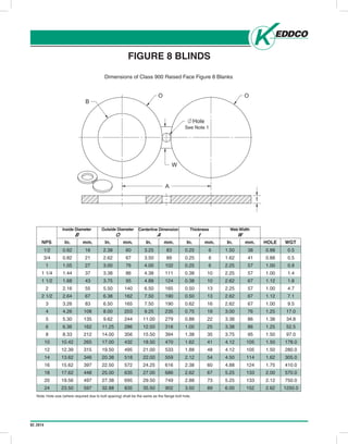
- 22. 02.2014 Head Office: P.O. Box 999, 645 Keddco Street, Sarnia, Ontario N7T 7K6 Telephone (519) 336-2960 Fax (519) 344-3181 4120 - 78 Avenue, Edmonton, Alberta T6B 3M8 Telephone (780) 438-4944 Fax (780) 435-3917 Toll Free 1-800-661-3809 www.keddco.com MFG. LTD. ISSUE-2005/10 NOTE: Hole size (where required due to bolt spacing) shall be the same as the flange bolt hole. FIGURE 8 BLINDS Dimensions of Class 900 Raised Face Figure 8 Blanks C7 NPS In. mm. In. mm. In. mm. In. mm. In. mm. HOLE WGT 1/2 0.62 16 2.38 60 3.25 83 0.25 6 1.50 38 0.88 0.5 3/4 0.82 21 2.62 67 3.50 89 0.25 6 1.62 41 0.88 0.5 1 1.05 27 3.00 76 4.00 102 0.25 6 2.25 57 1.00 0.9 1 1/4 1.44 37 3.38 86 4.38 111 0.38 10 2.25 57 1.00 1.4 1 1/2 1.68 43 3.75 95 4.88 124 0.38 10 2.62 67 1.12 1.8 2 2.16 55 5.50 140 6.50 165 0.50 13 2.25 57 1.00 4.7 2 1/2 2.64 67 6.38 162 7.50 190 0.50 13 2.62 67 1.12 7.1 3 3.26 83 6.50 165 7.50 190 0.62 16 2.62 67 1.00 9.5 4 4.26 108 8.00 203 9.25 235 0.75 19 3.00 76 1.25 17.0 5 5.30 135 9.62 244 11.00 279 0.88 22 3.38 86 1.38 34.8 6 6.36 162 11.25 286 12.50 318 1.00 25 3.38 86 1.25 52.5 8 8.33 212 14.00 356 15.50 394 1.38 35 3.75 95 1.50 97.0 10 10.42 265 17.00 432 18.50 470 1.62 41 4.12 105 1.50 178.0 12 12.39 315 19.50 495 21.00 533 1.88 48 4.12 105 1.50 280.0 14 13.62 346 20.38 518 22.00 559 2.12 54 4.50 114 1.62 305.0 16 15.62 397 22.50 572 24.25 616 2.38 60 4.88 124 1.75 410.0 18 17.62 448 25.00 635 27.00 686 2.62 67 5.25 133 2.00 570.0 20 19.56 497 27.38 695 29.50 749 2.88 73 5.25 133 2.12 750.0 24 23.50 597 32.88 835 35.50 902 3.50 89 6.00 152 2.62 1250.0 Inside Diameter B Outside Diameter O Centerline Dimension A Thickness t Web Width W FIGURE 8 BLINDS Note: Hole size (where required due to bolt spacing) shall be the same as the flange bolt hole. Inside Diameter B In. Outside Diameter O Centerline Dimension A Thickness t Web Width W mm. In. mm. In. mm. In. mm. In. mm.NPS HOLE WGT See Note 1 O O B W Hole A t Dimensions of Class 900 Raised Face Figure 8 Blanks
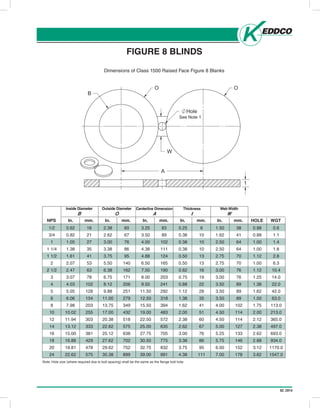
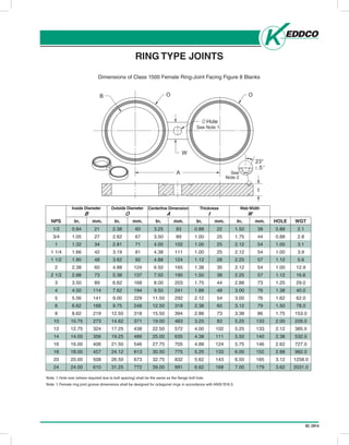
- 23. 02.2014 Head Office: P.O. Box 999, 645 Keddco Street, Sarnia, Ontario N7T 7K6 Telephone (519) 336-2960 Fax (519) 344-3181 4120 - 78 Avenue, Edmonton, Alberta T6B 3M8 Telephone (780) 438-4944 Fax (780) 435-3917 Toll Free 1-800-661-3809 www.keddco.com MFG. LTD. ISSUE-2005/10 FIGURE 8 BLINDS Dimensions of Class 1500 Raised Face Figure 8 Blanks C8 NOTE: Hole size (where required due to bolt spacing) shall be the same as the flange bolt hole. NPS In. mm. In. mm. In. mm. In. mm. In. mm. HOLE WGT 1/2 0.62 16 2.38 60 3.25 83 0.25 6 1.50 38 0.88 0.6 3/4 0.82 21 2.62 67 3.50 89 0.38 10 1.62 41 0.88 1.1 1 1.05 27 3.00 76 4.00 102 0.38 10 2.50 64 1.00 1.4 1 1/4 1.38 35 3.38 86 4.38 111 0.38 10 2.50 64 1.00 1.8 1 1/2 1.61 41 3.75 95 4.88 124 0.50 13 2.75 70 1.12 2.8 2 2.07 53 5.50 140 6.50 165 0.50 13 2.75 70 1.00 6.3 2 1/2 2.47 63 6.38 162 7.50 190 0.62 16 3.00 76 1.12 10.4 3 3.07 78 6.75 171 8.00 203 0.75 19 3.00 76 1.25 14.0 4 4.03 102 8.12 206 9.50 241 0.88 22 3.50 89 1.38 22.0 5 5.05 128 9.88 251 11.50 292 1.12 28 3.50 89 1.62 42.0 6 6.06 154 11.00 279 12.50 318 1.38 35 3.50 89 1.50 63.0 8 7.98 203 13.75 349 15.50 394 1.62 41 4.00 102 1.75 113.0 10 10.02 255 17.00 432 19.00 483 2.00 51 4.50 114 2.00 213.0 12 11.94 303 20.38 518 22.50 572 2.38 60 4.50 114 2.12 365.0 14 13.12 333 22.62 575 25.00 635 2.62 67 5.00 127 2.38 497.0 16 15.00 381 25.12 638 27.75 705 3.00 76 5.25 133 2.62 693.0 18 16.88 429 27.62 702 30.50 775 3.38 86 5.75 146 2.88 934.0 20 18.81 478 29.62 752 32.75 832 3.75 95 6.00 152 3.12 1170.0 24 22.62 575 35.38 899 39.00 991 4.38 111 7.00 178 3.62 1547.0 Inside Diameter B Outside Diameter O Centerline Dimension A Thickness t Web Width W FIGURE 8 BLINDS Note: Hole size (where required due to bolt spacing) shall be the same as the flange bolt hole. Inside Diameter B In. Outside Diameter O Centerline Dimension A Thickness t Web Width W mm. In. mm. In. mm. In. mm. In. mm.NPS HOLE WGT See Note 1 O O B W Hole A t Dimensions of Class 1500 Raised Face Figure 8 Blanks
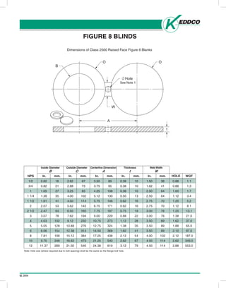
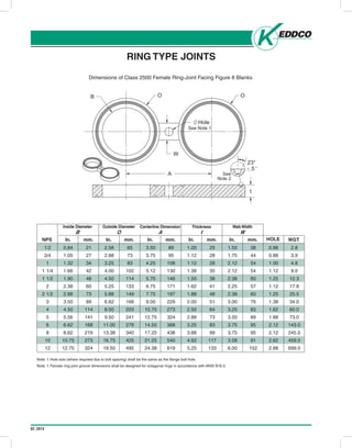
- 24. 02.2014 Head Office: P.O. Box 999, 645 Keddco Street, Sarnia, Ontario N7T 7K6 Telephone (519) 336-2960 Fax (519) 344-3181 4120 - 78 Avenue, Edmonton, Alberta T6B 3M8 Telephone (780) 438-4944 Fax (780) 435-3917 Toll Free 1-800-661-3809 www.keddco.com MFG. LTD. ISSUE-2005/10 NPS In. mm. In. mm. In. mm. In. mm. In. mm. WGT NOTE: Hole size (where required due to bolt spacing) shall be the same as the flange bolt hole. FIGURE 8 BLINDS Dimensions of Class 2500 Raised Face Figure 8 Blanks C9 1/2 0.62 16 2.62 67 3.50 89 0.38 10 1.50 38 0.88 1.1 3/4 0.82 21 2.88 73 3.75 95 0.38 10 1.62 41 0.88 1.3 1 1.05 27 3.25 83 4.25 108 0.38 10 2.50 64 1.00 1.7 1 1/4 1.38 35 4.00 102 5.12 130 0.50 13 2.50 64 1.12 3.4 1 1/2 1.61 41 4.50 114 5.75 146 0.62 16 2.75 70 1.25 5.2 2 2.07 53 5.62 143 6.75 171 0.62 16 2.75 70 1.12 8.1 2 1/2 2.47 63 6.50 165 7.75 197 0.75 19 3.00 76 1.25 13.1 3 3.07 78 7.62 194 9.00 229 0.88 22 3.00 76 1.38 21.0 4 4.03 102 9.12 232 10.75 273 1.12 28 3.50 89 1.62 37.0 5 5.05 128 10.88 276 12.75 324 1.38 35 3.50 89 1.88 65.0 6 6.06 154 12.38 314 14.50 368 1.62 41 3.50 89 2.12 97.0 8 7.81 198 15.12 384 17.25 438 2.12 54 4.00 102 2.12 187.0 10 9.75 248 18.62 473 21.25 540 2.62 67 4.50 114 2.62 349.0 12 11.37 289 21.50 546 24.38 619 3.12 79 4.50 114 2.88 553.0 Inside Diameter B Outside Diameter O Centerline Dimension A Thickness t Web Width W BOLT HOLE FIGURE 8 BLINDS Note: Hole size (where required due to bolt spacing) shall be the same as the flange bolt hole. Inside Diameter B In. Outside Diameter O Centerline Dimension A Thickness t Web Width W mm. In. mm. In. mm. In. mm. In. mm.NPS HOLE WGT See Note 1 O O B W Hole A t Dimensions of Class 2500 Raised Face Figure 8 Blanks
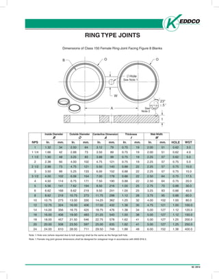
- 25. 02.2014 Head Office: P.O. Box 999, 645 Keddco Street, Sarnia, Ontario N7T 7K6 Telephone (519) 336-2960 Fax (519) 344-3181 4120 - 78 Avenue, Edmonton, Alberta T6B 3M8 Telephone (780) 438-4944 Fax (780) 435-3917 Toll Free 1-800-661-3809 www.keddco.com MFG. LTD. ISSUE-2005/10 RING TYPE JOINTS Dimensions of Class 150 Female Ring-Joint Facing Figure 8 Blanks NOTE: 1. Hole size (where required due to bolt spacing) shall be the same as the flange bolt hole. NOTE: 2. Female ring joint groove dimensions shall be designed for octagonal rings in accordance with ANSI B16.5. C10 NPS In. mm. In. mm. In. mm. In. mm. In. mm. WGT 1 1.32 34 2.50 64 3.12 79 0.75 19 2.00 51 0.62 3.0 1 1/4 1.66 42 2.88 73 3.50 89 0.75 19 2.00 51 0.62 4.0 1 1/2 1.90 48 3.25 83 3.88 99 0.75 19 2.25 57 0.62 5.0 2 2.38 60 4.00 102 4.75 121 0.75 19 2.25 57 0.75 5.0 2 1/2 2.88 73 4.75 121 5.50 140 0.88 22 2.25 57 0.75 10.0 3 3.50 89 5.25 133 6.00 152 0.88 22 2.25 57 0.75 15.0 3 1/2 4.00 102 6.06 154 7.00 178 0.88 22 2.50 64 0.75 17.5 4 4.50 114 6.75 171 7.50 190 0.88 22 2.50 64 0.75 20.0 5 5.56 141 7.62 194 8.50 216 1.00 25 2.75 70 0.88 30.0 6 6.62 168 8.62 219 9.50 241 1.00 25 3.25 83 0.88 40.0 8 8.62 219 10.75 273 11.75 298 1.12 28 3.75 95 0.88 60.0 10 10.75 273 13.00 330 14.25 362 1.25 32 4.00 102 1.00 80.0 12 12.75 324 16.00 406 17.00 432 1.38 35 4.75 121 1.00 100.0 14 14.00 356 16.75 425 18.75 476 1.38 34 5.00 127 1.12 120.0 16 16.00 406 19.00 483 21.25 540 1.50 38 5.00 127 1.12 150.0 18 18.00 457 21.50 546 22.75 578 1.62 41 5.00 127 1.25 200.0 20 20.00 508 23.50 597 25.00 635 1.62 41 5.00 127 1.25 250.0 24 24.00 610 28.00 711 29.50 749 1.88 48 6.00 152 1.38 400.0 Inside Diameter B Outside Diameter O Centerline Dimension A Thickness t Web Width W BOLT HOLE RING TYPE JOINTS Note: 1. Hole size (where required due to bolt spacing) shall be the same as the flange bolt hole. Note: 1. Female ring joint groove dimensions shall be designed for octagonal rings in accordance with ANSI B16.5. Inside Diameter B In. Outside Diameter O Centerline Dimension A Thickness t Web Width W mm. In. mm. In. mm. In. mm. In. mm.NPS HOLE WGT 23° .5 See Note 2 t See Note 1 OB O W Hole A Dimensions of Class 150 Female Ring-Joint Facing Figure 8 Blanks
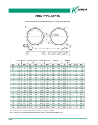
- 26. 02.2014 Head Office: P.O. Box 999, 645 Keddco Street, Sarnia, Ontario N7T 7K6 Telephone (519) 336-2960 Fax (519) 344-3181 4120 - 78 Avenue, Edmonton, Alberta T6B 3M8 Telephone (780) 438-4944 Fax (780) 435-3917 Toll Free 1-800-661-3809 www.keddco.com MFG. LTD. ISSUE-2005/10 RING TYPE JOINTS Dimensions of Class 300 Female Ring-Joint Facing Figure 8 Blanks NOTE: 1. Hole size (where required due to bolt spacing) shall be the same as the flange bolt hole. NOTE: 2. Female ring joint groove dimensions shall be designed for octagonal rings in accordance with ANSI B16.5. C11 NPS In. mm. In. mm. In. mm. In. mm. In. mm. HOLE WGT 1/2 0.84 21 2.00 51 2.62 67 0.62 16 1.50 38 0.62 2.0 3/4 1.05 27 2.50 64 3.25 83 0.75 19 1.75 44 0.75 3.0 1 1.32 34 2.75 70 3.50 89 0.75 19 2.00 51 0.75 3.0 1 1/4 1.66 42 3.12 79 3.88 99 0.88 22 2.00 51 0.75 4.0 1 1/2 1.90 48 3.56 90 4.50 114 0.88 22 2.25 57 0.88 5.0 2 2.38 60 4.25 108 5.00 127 1.00 25 2.25 57 0.75 10.0 2 1/2 2.88 73 5.00 127 5.88 149 1.12 28 2.25 57 0.88 10.0 3 3.50 89 5.75 146 6.62 168 1.12 28 2.25 57 0.88 15.0 3 1/2 4.00 102 6.25 159 7.25 184 1.12 28 2.50 64 0.88 17.5 4 4.50 114 6.88 175 7.88 2 1.25 32 2.50 64 0.88 20.0 5 5.56 141 8.25 210 9.25 235 1.38 35 2.75 70 0.88 30.0 6 6.62 168 9.50 241 10.62 270 1.38 35 3.25 83 0.88 40.0 8 8.62 219 11.88 302 13.00 330 1.62 41 3.75 95 1.00 80.0 10 10.75 273 14.00 356 15.25 387 1.75 44 4.00 102 1.12 100.0 12 12.75 324 16.25 413 17.75 451 2.00 51 4.75 121 1.25 150.0 14 14.00 356 18.00 457 20.25 514 2.12 54 5.00 127 1.25 200.0 16 16.00 406 20.00 508 22.50 572 2.25 57 5.00 127 1.38 250.0 18 18.00 457 22.62 575 24.75 629 2.38 60 5.00 127 1.38 350.0 20 20.00 508 25.00 635 27.00 686 2.75 70 5.00 127 1.38 500.0 24 24.00 610 29.50 749 32.00 813 3.12 79 6.00 152 1.62 800.0 Inside Diameter B Outside Diameter O Centerline Dimension A Thickness t Web Width W RING TYPE JOINTS Note: 1. Hole size (where required due to bolt spacing) shall be the same as the flange bolt hole. Note: 1. Female ring joint groove dimensions shall be designed for octagonal rings in accordance with ANSI B16.5. Inside Diameter B In. Outside Diameter O Centerline Dimension A Thickness t Web Width W mm. In. mm. In. mm. In. mm. In. mm.NPS HOLE WGT 23° .5 See Note 2 t See Note 1 OB O W Hole A Dimensions of Class 300 Female Ring-Joint Facing Figure 8 Blanks
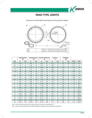
- 27. 02.2014Head Office: P.O. Box 999, 645 Keddco Street, Sarnia, Ontario N7T 7K6 Telephone (519) 336-2960 Fax (519) 344-3181 4120 - 78 Avenue, Edmonton, Alberta T6B 3M8 Telephone (780) 438-4944 Fax (780) 435-3917 Toll Free 1-800-661-3809 www.keddco.com MFG. LTD. ISSUE-2005/10 RING TYPE JOINTS Dimensions of Class 600 Female Ring-Joint Facing Figure 8 Blanks C12 NOTE: 1. Hole size (where required due to bolt spacing) shall be the same as the flange bolt hole. NOTE: 2. Female ring joint groove dimensions shall be designed for octagonal rings in accordance with ANSI B16.5. NPS In. mm. In. mm. In. mm. In. mm. In. mm. WGT 1/2 0.84 21 2.00 51 2.62 67 0.75 19 1.50 38 0.62 2.0 3/4 1.05 27 2.50 64 3.25 83 0.88 22 1.75 44 0.75 3.0 1 1.32 34 2.75 70 3.50 89 0.88 22 2.00 51 0.75 3.0 1 1/4 1.66 42 3.12 79 3.88 99 0.88 22 2.00 51 0.75 4.0 1 1/2 1.90 48 3.56 90 4.50 114 0.88 22 2.25 57 0.88 5.0 2 2.38 60 4.25 108 5.00 127 1.12 28 2.25 57 0.75 10.0 2 1/2 2.88 73 5.00 127 5.88 149 1.25 32 2.25 57 0.88 10.0 3 3.50 89 5.75 146 6.62 168 1.25 32 2.25 57 0.88 15.0 3 1/2 4.00 102 6.25 159 7.25 184 1.38 35 2.50 64 1.00 17.5 4 4.50 114 6.88 175 8.50 216 1.38 35 2.50 64 1.00 20.0 5 5.56 141 8.25 210 10.50 267 1.50 38 2.75 70 1.12 30.0 6 6.62 168 9.50 241 11.50 292 1.75 44 3.25 83 1.12 40.0 8 8.62 219 11.88 302 13.75 349 2.00 51 3.75 95 1.25 80.0 10 10.75 273 14.00 356 17.00 432 2.25 57 4.00 102 1.38 130.0 12 12.75 324 16.25 413 19.25 489 2.50 64 4.75 121 1.38 200.0 14 14.00 356 18.00 457 20.75 527 2.62 67 5.00 127 1.50 250.0 16 16.00 406 20.00 508 23.75 603 2.88 73 5.00 127 1.62 350.0 18 18.00 457 22.62 575 25.75 654 3.12 79 5.00 127 1.75 500.0 20 20.00 508 25.00 635 28.50 724 3.50 89 5.00 127 1.75 650.0 24 24.00 610 29.50 749 33.00 838 4.12 105 6.00 152 2.00 1000.0 Inside Diameter B Outside Diameter O Centerline Dimension A Thickness t Web Width W BOLT HOLE RING TYPE JOINTS Note: 1. Hole size (where required due to bolt spacing) shall be the same as the flange bolt hole. Note: 1. Female ring joint groove dimensions shall be designed for octagonal rings in accordance with ANSI B16.5. Inside Diameter B In. Outside Diameter O Centerline Dimension A Thickness t Web Width W mm. In. mm. In. mm. In. mm. In. mm.NPS BOLT HOLE WGT 23° .5 See Note 2 t See Note 1 OB O W Hole A Dimensions of Class 600 Female Ring-Joint Facing Figure 8 Blanks
- 28. 02.2014 Head Office: P.O. Box 999, 645 Keddco Street, Sarnia, Ontario N7T 7K6 Telephone (519) 336-2960 Fax (519) 344-3181 4120 - 78 Avenue, Edmonton, Alberta T6B 3M8 Telephone (780) 438-4944 Fax (780) 435-3917 Toll Free 1-800-661-3809 www.keddco.com MFG. LTD. ISSUE-2005/10 NOTE: 1. Hole size (where required due to bolt spacing) shall be the same as the flange bolt hole. NOTE: 2. Female ring joint groove dimensions shall be designed for octagonal rings in accordance with ANSI B16.5. RING TYPE JOINTS Dimensions of Class 900 Female Ring-Joint Facing Figure 8 Blanks C13 NPS In. mm. In. mm. In. mm. In. mm. In. mm. WGT 1/2 0.84 21 2.38 60 3.25 83 0.88 22 1.50 38 0.88 3.0 3/4 1.05 27 2.62 67 3.50 89 0.88 22 1.75 44 0.88 4.0 1 1.32 34 2.81 71 4.00 102 0.88 22 2.00 51 1.00 5.0 1 1/4 1.66 42 3.19 81 4.38 111 1.00 25 2.00 51 1.00 5.0 1 1/2 1.90 48 3.62 92 4.88 124 1.00 25 2.50 64 1.12 5.0 2 2.38 60 4.88 124 6.50 165 1.25 32 2.00 51 1.00 10.0 2 1/2 2.88 73 5.38 137 7.50 190 1.38 35 2.62 67 1.12 15.0 3 3.50 89 6.12 156 7.50 190 1.38 35 2.62 67 1.00 20.0 4 4.50 114 7.12 181 9.25 235 1.62 41 2.88 73 1.25 30.0 5 5.56 141 8.50 216 11.00 279 1.75 44 2.88 73 1.38 45.0 6 6.62 168 9.50 241 12.50 318 1.88 48 2.88 73 1.25 60.0 8 8.62 219 12.12 308 15.50 394 2.25 57 3.12 79 1.50 100.0 10 10.75 273 14.25 362 18.50 470 2.50 64 4.75 121 1.50 150.0 12 12.75 324 16.50 419 21.00 533 2.88 73 4.75 121 1.50 250.0 14 14.00 356 18.38 467 22.00 559 3.25 83 4.75 121 1.62 250.0 16 16.00 406 20.62 524 24.25 616 3.62 92 5.00 127 1.75 450.0 18 18.00 457 23.38 594 27.00 686 4.00 102 5.25 133 2.00 700.0 20 20.00 508 25.50 648 29.50 749 4.38 111 5.00 127 2.12 900.0 24 24.00 610 30.38 772 35.50 902 5.25 133 5.50 140 2.62 1100.0 Inside Diameter B Outside Diameter O Centerline Dimension A Thickness t Web Width W BOLT HOLE SIZE RING TYPE JOINTS Note: 1. Hole size (where required due to bolt spacing) shall be the same as the flange bolt hole. Note: 1. Female ring joint groove dimensions shall be designed for octagonal rings in accordance with ANSI B16.5. Inside Diameter B In. Outside Diameter O Centerline Dimension A Thickness t Web Width W mm. In. mm. In. mm. In. mm. In. mm.NPS HOLE WGT 23° .5 See Note 2 t See Note 1 OB O W Hole A Dimensions of Class 900 Female Ring-Joint Facing Figure 8 Blanks
- 29. 02.2014 Head Office: P.O. Box 999, 645 Keddco Street, Sarnia, Ontario N7T 7K6 Telephone (519) 336-2960 Fax (519) 344-3181 4120 - 78 Avenue, Edmonton, Alberta T6B 3M8 Telephone (780) 438-4944 Fax (780) 435-3917 Toll Free 1-800-661-3809 www.keddco.com MFG. LTD. ISSUE-2005/10 NOTE: 1. Hole size (where required due to bolt spacing) shall be the same as the flange bolt hole. NOTE: 2. Female ring joint groove dimensions shall be designed for octagonal rings in accordance with ANSI B16.5. RING TYPE JOINTS Dimensions of Class 1500 Female Ring-Joint Facing Figure 8 Blanks C14 NPS In. mm. In. mm. In. mm. In. mm. In. mm. WGT 1/2 0.84 21 2.38 60 3.25 83 0.88 22 1.50 38 0.88 2.1 3/4 1.05 27 2.62 67 3.50 89 1.00 25 1.75 44 0.88 2.8 1 1.32 34 2.81 71 4.00 102 1.00 25 2.12 54 1.00 3.1 1 1/4 1.66 42 3.19 81 4.38 111 1.00 25 2.12 54 1.00 3.9 1 1/2 1.90 48 3.62 92 4.88 124 1.12 28 2.25 57 1.12 5.6 2 2.38 60 4.88 124 6.50 165 1.38 35 2.12 54 1.00 12.9 2 1/2 2.88 73 5.38 137 7.50 190 1.50 38 2.25 57 1.12 16.6 3 3.50 89 6.62 168 8.00 203 1.75 44 2.88 73 1.25 29.0 4 4.50 114 7.62 194 9.50 241 1.88 48 3.00 76 1.38 40.0 5 5.56 141 9.00 229 11.50 292 2.12 54 3.00 76 1.62 62.0 6 6.62 168 9.75 248 12.50 318 2.38 60 3.12 79 1.50 78.0 8 8.62 219 12.50 318 15.50 394 2.88 73 3.38 86 1.75 153.0 10 10.75 273 14.62 371 19.00 483 3.25 83 5.25 133 2.00 226.0 12 12.75 324 17.25 438 22.50 572 4.00 102 5.25 133 2.12 385.0 14 14.00 356 19.25 489 25.00 635 4.38 111 5.50 140 2.38 532.0 16 16.00 406 21.50 546 27.75 705 4.88 124 5.75 146 2.62 727.0 18 18.00 457 24.12 613 30.50 775 5.25 133 6.00 152 2.88 982.0 20 20.00 508 26.50 673 32.75 832 5.62 143 6.50 165 3.12 1258.0 24 24.00 610 31.25 772 39.00 991 6.62 168 7.00 179 3.62 2031.0 Inside Diameter B Outside Diameter O Centerline Dimension A Thickness t Web Width W BOLT HOLE RING TYPE JOINTS Note: 1. Hole size (where required due to bolt spacing) shall be the same as the flange bolt hole. Note: 1. Female ring joint groove dimensions shall be designed for octagonal rings in accordance with ANSI B16.5. Inside Diameter B In. Outside Diameter O Centerline Dimension A Thickness t Web Width W mm. In. mm. In. mm. In. mm. In. mm.NPS HOLE WGT 23° .5 See Note 2 t See Note 1 OB O W Hole A Dimensions of Class 1500 Female Ring-Joint Facing Figure 8 Blanks
- 30. 02.2014 Head Office: P.O. Box 999, 645 Keddco Street, Sarnia, Ontario N7T 7K6 Telephone (519) 336-2960 Fax (519) 344-3181 4120 - 78 Avenue, Edmonton, Alberta T6B 3M8 Telephone (780) 438-4944 Fax (780) 435-3917 Toll Free 1-800-661-3809 www.keddco.com MFG. LTD. ISSUE-2005/10 C15 NOTE: 1. Hole size (where required due to bolt spacing) shall be the same as the flange bolt hole. NOTE: 2. Female ring joint groove dimensions shall be designed for octagonal rings in accordance with ANSI B16.5. RING TYPE JOINTS Dimensions of Class 2500 Female Ring-Joint Facing Figure 8 Blanks NPS In. mm. In. mm. In. mm. In. mm. In. mm. WGT 1/2 0.84 21 2.56 65 3.50 89 1.00 25 1.50 38 0.88 2.8 3/4 1.05 27 2.88 73 3.75 95 1.12 28 1.75 44 0.88 3.9 1 1.32 34 3.25 83 4.25 108 1.12 28 2.12 54 1.00 4.8 1 1/4 1.66 42 4.00 102 5.12 130 1.38 35 2.12 54 1.12 9.0 1 1/2 1.90 48 4.50 114 5.75 146 1.50 38 2.38 60 1.25 12.3 2 2.38 60 5.25 133 6.75 171 1.62 41 2.25 57 1.12 17.8 2 1/2 2.88 73 5.88 149 7.75 197 1.88 48 2.38 60 1.25 25.5 3 3.50 89 6.62 168 9.00 229 2.00 51 3.00 76 1.38 34.0 4 4.50 114 8.00 203 10.75 273 2.50 64 3.25 83 1.62 60.0 5 5.56 141 9.50 241 12.75 324 2.88 73 3.50 89 1.88 73.0 6 6.62 168 11.00 279 14.50 368 3.25 83 3.75 95 2.12 143.0 8 8.62 219 13.38 340 17.25 438 3.88 99 3.75 95 2.12 245.0 10 10.75 273 16.75 425 21.25 540 4.62 117 3.58 91 2.62 459.0 12 12.75 324 19.50 495 24.38 619 5.25 133 6.00 152 2.88 699.0 Inside Diameter B Outside Diameter O Centerline Dimension A Thickness t Web Width W BOLT HOLE RING TYPE JOINTS Note: 1. Hole size (where required due to bolt spacing) shall be the same as the flange bolt hole. Note: 1. Female ring joint groove dimensions shall be designed for octagonal rings in accordance with ANSI B16.5. Inside Diameter B In. Outside Diameter O Centerline Dimension A Thickness t Web Width W mm. In. mm. In. mm. In. mm. In. mm.NPS HOLE WGT 23° .5 See Note 2 t See Note 1 OB O W Hole A Dimensions of Class 2500 Female Ring-Joint Facing Figure 8 Blanks
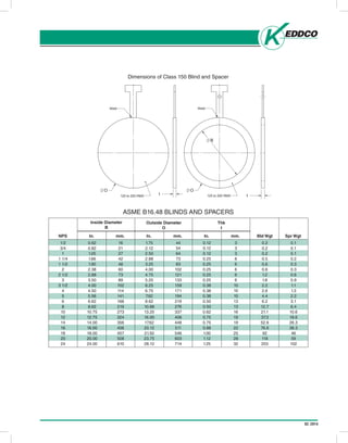
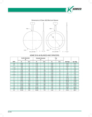
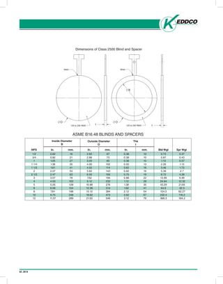
- 31. 02.2014 Dimensions of Class 150 Blind and Spacer t Weld 125 to 250 RMS O Weld 125 to 250 RMS O B t ASME B16.48 BLINDS AND SPACERS Outside Diameter O 1/2 3/4 1 1 1/4 1 1/2 2 2 1/2 3 3 1/2 4 5 6 8 10 12 14 16 18 20 24 0.62 0.82 1.05 1.66 1.90 2.38 2.88 3.50 4.00 4.50 5.56 6.62 8.62 10.75 12.75 14.00 16.00 18.00 20.00 24.00 NPS Inside Diameter B Thk t In. mm. In. mm. In. mm. 16 21 27 42 48 60 73 89 102 114 141 168 219 273 324 356 406 457 508 610 1.75 2.12 2.50 2.88 3.25 4.00 4.75 5.25 6.25 6.75 7.62 8.62 10.88 13.25 16.00 17.62 20.12 21.50 23.75 28.12 44 54 64 73 83 102 121 133 159 171 194 219 276 337 406 448 511 546 603 714 0.12 0.12 0.12 0.25 0.25 0.25 0.25 0.25 0.38 0.38 0.38 0.50 0.50 0.62 0.75 0.75 0.88 1.00 1.12 1.25 3 3 3 6 6 6 6 6 10 10 10 13 13 16 19 19 22 25 28 32 Bld Wgt Spr Wgt 0.2 0.2 0.2 0.5 0.6 0.6 1.2 1.8 2.2 2.6 4.4 6.2 12.7 21.1 37.3 52.6 76.6 92 118 203 0.1 0.1 0.1 0.2 0.3 0.3 0.6 0.9 1.1 1.3 2.2 3.1 6.4 10.6 18.6 26.3 38.3 46 59 102
- 32. 02.2014 Dimensions of Class 300 Blind and Spacer t Weld 125 to 250 RMS O Weld 125 to 250 RMS O B t ASME B16.48 BLINDS AND SPACERS Outside Diameter O 1/2 3/4 1 1 1/4 1 1/2 2 2 1/2 3 3 1/2 4 5 6 8 10 12 14 16 18 20 24 0.62 0.82 1.05 1.66 1.90 2.38 2.88 3.50 4.00 4.50 5.56 6.62 8.62 10.75 12.75 14.00 16.00 18.00 20.00 24.00 NPS Inside Diameter B Thk t In. mm. In. mm. In. mm. 16 21 27 42 48 60 73 89 102 114 141 168 219 273 324 356 406 457 508 610 2.00 2.50 2.75 3.12 3.62 4.25 5.00 5.75 6.38 7.00 8.38 9.75 12.00 14.12 16.50 19.00 21.12 23.38 25.62 30.38 51 64 70 79 92 108 127 146 162 178 213 248 305 359 419 483 537 594 651 772 0.25 0.25 0.25 0.25 0.25 0.38 0.38 0.38 0.50 0.50 0.62 0.62 0.88 1.00 1.12 1.25 1.50 1.62 1.75 2.00 6 6 6 6 6 10 10 10 13 13 16 16 22 25 28 32 38 41 44 51 Bld Wgt Spr Wgt 0.33 0.33 0.33 0.6 0.87 1.2 1.6 1.93 3.6 5.19 9.32 13.39 26.64 43.29 68.6 101.9 143.2 196.5 249 416.3 0.17 0.17 0.17 0.3 0.43 0.6 0.8 0.97 1.8 2.6 4.66 6.69 13.32 21.65 34.3 50.95 71.6 98.24 124.5 208.1
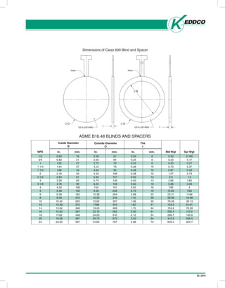
- 33. 02.2014 Dimensions of Class 600 Blind and Spacer t Weld 125 to 250 RMS O Weld 125 to 250 RMS O B t ASME B16.48 BLINDS AND SPACERS Outside Diameter O 1/2 3/4 1 1 1/4 1 1/2 2 2 1/2 3 3 1/2 4 5 6 8 10 12 14 16 18 20 24 0.62 0.82 1.05 1.44 1.68 2.16 2.64 3.26 3.76 4.26 5.30 6.36 8.33 10.42 12.39 13.62 15.62 17.62 19.56 23.50 NPS Inside Diameter B Thk t In. mm. In. mm. In. mm. 16 21 27 37 43 55 67 83 96 108 135 162 212 265 315 346 397 448 497 597 2.00 2.50 2.75 3.12 3.62 4.25 5.00 5.75 6.25 7.50 9.38 10.38 12.50 15.62 17.88 19.25 22.12 24.00 26.75 31.00 51 64 70 79 92 108 127 146 159 191 238 264 318 397 454 489 562 610 679 787 0.25 0.25 0.25 0.38 0.38 0.38 0.50 0.50 0.62 0.62 0.75 0.88 1.12 1.38 1.62 1.75 2.00 2.12 2.50 2.88 6 6 6 10 10 10 13 13 16 16 19 22 28 35 41 44 51 54 64 73 Bld Wgt Spr Wgt 0.33 0.33 0.53 0.73 0.87 1.47 2.6 3.66 5.86 7.99 15.65 23.31 39.96 78.26 123.2 153.2 226.4 299.7 412.9 649.4 0.165 0.17 0.27 0.37 0.43 0.73 1.3 1.83 2.93 4 7.83 11.66 19.98 39.13 61.61 76.59 113.2 149.9 206.5 324.7
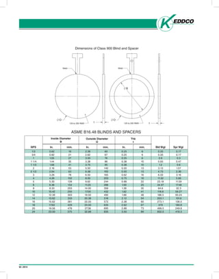
- 34. 02.2014 Dimensions of Class 900 Blind and Spacer t Weld 125 to 250 RMS O Weld 125 to 250 RMS O B t ASME B16.48 BLINDS AND SPACERS Outside Diameter O 1/2 3/4 1 1 1/4 1 1/2 2 2 1/2 3 4 5 6 8 10 12 14 16 18 20 24 0.62 0.82 1.05 1.44 1.68 2.16 2.64 3.26 4.26 5.30 6.36 8.33 10.42 12.39 13.62 15.62 17.62 19.56 23.50 NPS Inside Diameter B Thk t In. mm. In. mm. In. mm. 16 21 27 35 41 53 63 78 102 128 154 203 255 303 333 381 429 478 575 2.38 2.62 3.00 3.38 3.75 5.50 6.38 6.50 8.00 9.62 11.25 14.00 17.00 19.50 20.38 22.50 25.00 27.38 32.88 60 67 76 86 95 140 162 165 203 244 286 356 432 495 518 572 635 695 835 0.25 0.25 0.25 0.38 0.38 0.50 0.50 0.62 0.75 0.88 1.00 1.38 1.62 1.88 2.12 2.38 2.62 2.88 3.50 6 6 6 10 10 13 13 16 19 22 25 35 41 48 54 60 67 73 89 Bld Wgt Spr Wgt 0.33 0.33 0.6 0.93 1.2 3.13 4.73 6.33 11.32 23.18 34.97 64.6 118.6 186.5 203.1 273.1 379 499.5 832.5 0.17 0.17 0.3 0.47 0.6 1.57 2.36 3.16 5.66 11.59 17.48 32.3 59.27 93.24 101.6 136.5 189.8 249.8 416.3
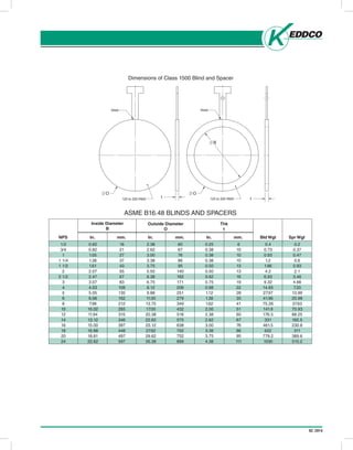
- 35. 02.2014 Dimensions of Class 1500 Blind and Spacer t Weld 125 to 250 RMS O Weld 125 to 250 RMS O B t ASME B16.48 BLINDS AND SPACERS Outside Diameter O 1/2 3/4 1 1 1/4 1 1/2 2 2 1/2 3 4 5 6 8 10 12 14 16 18 20 24 0.62 0.82 1.05 1.38 1.61 2.07 2.47 3.07 4.03 5.05 6.06 7.98 10.02 11.94 13.12 15.00 16.88 18.81 22.62 NPS Inside Diameter B Thk t In. mm. In. mm. In. mm. 16 21 27 37 43 55 67 83 108 135 162 212 265 315 346 397 448 497 597 2.38 2.62 3.00 3.38 3.75 5.50 6.38 6.75 8.12 9.88 11.00 13.75 17.00 20.38 22.62 25.12 27.62 29.62 35.38 60 67 76 86 95 140 162 171 206 251 279 349 432 518 575 638 702 752 899 0.25 0.38 0.38 0.38 0.50 0.50 0.62 0.75 0.88 1.12 1.38 1.62 2.00 2.38 2.62 3.00 3.38 3.75 4.38 6 10 10 10 13 13 16 19 22 28 35 41 51 60 67 76 86 95 111 Bld Wgt Spr Wgt 0.4 0.73 0.93 1.2 1.86 4.2 6.93 9.32 14.65 27.97 41.96 75.26 141.9 176.5 331 461.5 622 779.2 1030 0.2 0.37 0.47 0.6 0.93 2.1 3.46 4.66 7.33 13.99 20.98 37.63 70.93 88.25 165.5 230.8 311 389.6 515.2
- 36. 02.2014 Dimensions of Class 2500 Blind and Spacer t Weld 125 to 250 RMS O Weld 125 to 250 RMS O B t ASME B16.48 BLINDS AND SPACERS Outside Diameter O 1/2 3/4 1 1 1/4 1 1/2 2 2 1/2 3 4 5 6 8 10 12 NPS Inside Diameter B Thk t In. mm. In. mm. In. mm. 16 21 27 35 41 53 63 78 102 128 154 198 248 289 2.62 2.88 3.25 4.00 4.50 5.62 6.50 7.62 9.12 10.88 12.38 15.12 18.62 21.50 67 73 83 102 114 143 165 194 232 276 314 384 473 546 0.38 0.38 0.38 0.50 0.62 0.62 0.75 0.88 1.12 1.38 1.62 2.12 2.62 3.12 10 10 10 13 16 16 19 22 28 35 41 54 67 79 Bld Wgt Spr Wgt 0.73 0.87 1.13 2.26 3.46 5.39 8.72 13.99 24.64 43.29 64.6 124.5 232.4 368.3 0.37 0.43 0.57 1.13 1.73 2.7 4.36 6.99 12.32 21.65 32.3 62.27 116.2 184.2 0.62 0.82 1.05 1.38 1.61 2.07 2.47 3.07 4.03 5.05 6.06 7.81 9.75 11.37
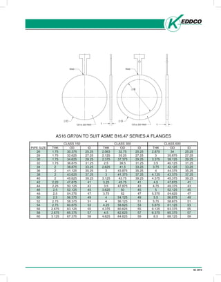
- 37. 02.2014 Head Office: P.O. Box 999, 645 Keddco Street, Sarnia, Ontario N7T 7K6 Telephone (519) 336-2960 Fax (519) 344-3181 4120 - 78 Avenue, Edmonton, Alberta T6B 3M8 Telephone (780) 438-4944 Fax (780) 435-3917 Toll Free 1-800-661-3809 www.keddco.com MFG. LTD. ISSUE-2005/10 C22 A516 GR70N TO SUIT ASME B16.47 SERIES A FLANGES t Weld 125 to 250 RMS O Weld 125 to 250 RMS O B t
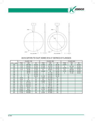
- 38. 02.2014 Head Office: P.O. Box 999, 645 Keddco Street, Sarnia, Ontario N7T 7K6 Telephone (519) 336-2960 Fax (519) 344-3181 4120 - 78 Avenue, Edmonton, Alberta T6B 3M8 Telephone (780) 438-4944 Fax (780) 435-3917 Toll Free 1-800-661-3809 www.keddco.com MFG. LTD. ISSUE-2005/10 C23 A516 GR70N TO SUIT ASME B16.47 SERIES B FLANGES t Weld 125 to 250 RMS O Weld 125 to 250 RMS O B t
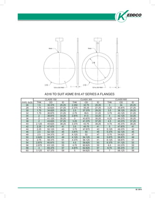
- 39. 02.2014 Head Office: P.O. Box 999, 645 Keddco Street, Sarnia, Ontario N7T 7K6 Telephone (519) 336-2960 Fax (519) 344-3181 4120 - 78 Avenue, Edmonton, Alberta T6B 3M8 Telephone (780) 438-4944 Fax (780) 435-3917 Toll Free 1-800-661-3809 www.keddco.com MFG. LTD. ISSUE-2005/10 C24 A316 TO SUIT ASME B16.47 SERIES A FLANGES t Weld 125 to 250 RMS O Weld 125 to 250 RMS O B t
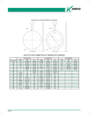
- 40. 02.2014 Head Office: P.O. Box 999, 645 Keddco Street, Sarnia, Ontario N7T 7K6 Telephone (519) 336-2960 Fax (519) 344-3181 4120 - 78 Avenue, Edmonton, Alberta T6B 3M8 Telephone (780) 438-4944 Fax (780) 435-3917 Toll Free 1-800-661-3809 www.keddco.com MFG. LTD. ISSUE-2005/10 C25 A316 TO SUIT ASME B16.47 SERIES B FLANGES Dimensions of Class 900 Bind and Spacer t Weld 125 to 250 RMS O Weld 125 to 250 RMS O B t
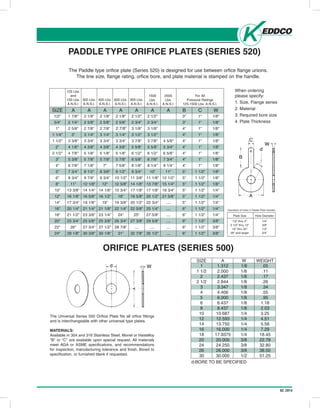
- 41. 02.2014 PADDLE TYPE ORIFICE PLATES (SERIES 520) Head Office: P.O. Box 999, 645 Keddco Street, Sarnia, Ontario N7T 7K6 Telephone (519) 336-2960 Fax (519) 344-3181 4120 - 78 Avenue, Edmonton, Alberta T6B 3M8 Telephone (780) 438-4944 Fax (780) 435-3917 Toll Free 1-800-661-3809 www.keddco.com MFG. LTD. ISSUE-2005/10 PADDLE TYPE ORIFICE PLATES (SERIES 520) (Series 520) The Paddle type orifice plate (Series 520) is designed for use between orfice flange unions. The line size, flange rating, orfice bore, and plate material is stamped on the handle. ORIFICE PLATES (SERIES 500) C26 125 Lbs. and 150 Lbs. A.N.S.I. 300 Lbs. A.N.S.I. 400 Lbs. A.N.S.I. 600 Lbs. A.N.S.I. 900 Lbs. A.N.S.I. 1500 Lbs. A.N.S.I. 2500 Lbs. A.N.S.I. For All Pressure Ratings 125-1500 Lbs. A.N.S.I. SIZE 1/2" 3/4" 1" 1 1/4" 1 1/2" 2" 2 1/2" 3" 4" 5" 6" 8" 10" 12" 14" 16" 18" 20" 22" 24" A 1 7/8" 2 1/4" 2 5/8" 3" 3 3/8" 4 1/8" 4 7/8" 5 3/8" 6 7/8" 7 3/4" 8 3/4" 11" 13 3/8" 16 1/8" 17 3/4" 20 1/4" 21 1/2" 23 3/4" 26" 28 1/8" A 2 1/8" 2 5/8" 2 7/8" 3 1/4" 3 3/4" 4 3/8" 5 1/8" 5 7/8" 7 1/8" 8 1/2" 9 7/8" 12 1/8" 14 1/4" 16 5/8" 19 1/8" 21 1/4" 23 3/8" 25 5/8" 27 3/4" 30 3/8" A 2 1/8" 2 5/8" 2 7/8" 3 1/4" 3 3/4" 4 3/8" 5 1/8" 5 7/8" 7" 8 3/8" 9 3/4" 12" 14 1/8" 16 1/2" 19" 21 1/8" 23 1/4" 25 3/8" 27 1/2" 30 1/8" A 2 1/8" 2 5/8" 3 7/8" 3 1/4" 3 3/4" 4 3/8" 5 1/8" 5 7/8" 7 5/8" 9 1/2" 10 1/2" 12 5/8" 15 3/4" 18" 19 3/8" 22 1/4" 24" 26 3/4" 28 7/8" 31" A 2 1/2" 2 3/4" 3 1/8" 3 1/2" 3 7/8" 5 5/8" 6 1/2" 6 5/8" 8 1/8" 9 3/4" 11 3/8" 14 1/8" 17 1/8" 19 5/8" 20 1/2" 22 5/8" 25" 27 3/8" .... 32 7/8" A 2 1/2" 2 3/4" 3 1/8" 3 1/2" 3 7/8" 5 5/8" 6 1/2" 6 7/8" 8 1/4" 10" 11 1/8" 13 7/8" 17 1/8" 20 1/2" 22 3/4" 25 1/4" 27 5/8" 29 5/8" .... 35 1/2" A 4 5/8" 5 3/4" 6 5/8" 7 3/4" 9 1/4" 11" 12 1/2" 15 1/4" 18 3/4" 21 5/8" .... .... .... .... .... .... B 3" 3" 4" 4" 4" 4" 4" 4" 4" 5" 5" 5" 5" 5" 5" 6" 6" 6" 6" 6" C 1" 1" 1" 1" 1" 1" 1" 1" 1" 1 1/2" 1 1/2" 1 1/2" 1 1/2" 1 1/2" 1 1/2" 1 1/2" 1 1/2" 1 1/2" 1 1/2" 1 1/2" W 1/8" 1/8" 1/8" 1/8" 1/8" 1/8" 1/8" 1/8" 1/8" 1/8" 1/8" 1/8" 1/4" 1/4" 1/4" 1/4" 1/4" 3/8" 3/8" 3/8" When ordering please specify: 1. Size, Flange series 2. Material 3. Required bore size 4. Plate Thickness The Universal Series 500 Orifice Plate fits all orfice fittings and is interchangeable with other universal type plates. MATERIALS: Available in 304 and 316 Stainless Steel, Monel or Hastelloy "B" or "C" are available upon special request. All materials meet AGA or ASME specifications, and recommendations for inspection, manufacturing tolerance and finish. Bored to specification, or furnished blank if requested. SIZE A W WEIGHT .05 .11 .17 .26 .34 .55 .95 1.18 2.03 3.25 4.51 5.58 7.29 18.45 22.78 32.80 38.50 51.25 1/8 1/8 1/8 1/8 1/8 1/8 1/8 1/8 1/8 1/4 1/4 1/4 1/4 1/4 3/8 3/8 3/8 1/2 1.312 2.000 2.437 2.844 3.347 4.406 6.000 6.437 8.437 10.687 12.593 13.750 16.000 17.9375 20.000 24.250 26.000 30.000 1 1 1/2 2 2 1/2 3 4 5 6 8 10 12 14 16 18 20 24 26 30 d-BORE TO BE SPECIFIED Plate Size Hole Diameter 1/2” thru 2” 1/4” 2 1/2” thru 12” 3/8” 14” thru 24” 1/2” 26” and larger 3/4” Diameters of holes in Paddle Plate Handles 2 7/8”
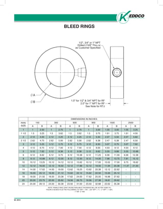
- 42. 02.2014 BLEED RINGS Head Office: P.O. Box 999, 645 Keddco Street, Sarnia, Ontario N7T 7K6 Telephone (519) 336-2960 Fax (519) 344-3181 4120 - 78 Avenue, Edmonton, Alberta T6B 3M8 Telephone (780) 438-4944 Fax (780) 435-3917 Toll Free 1-800-661-3809 www.keddco.com MFG. LTD. ISSUE-2005/10 3/4 NPT. Drilled 5/8 through or Customer Specified C27 BLEED RINGS DIMENSIONS IN INCHES 150 300 600 900 1500 2500PIPE SIZE A 1 1.5 2.12 2.62 3.12 4.12 5.12 6.12 8.12 10.12 12.12 14.00 16.00 18.00 20.00 24.00 1 1 1/2 2 2 1/2 3 4 5 6 8 10 12 14 16 18 20 24 B 2.50 3.25 4.00 4.75 5.25 6.75 7.62 8.62 10.88 13.25 16.00 17.62 20.12 21.50 23.75 28.12 A 1 1.5 2.12 2.62 3.12 4.12 5.12 6.12 8.12 10.12 12.12 14.00 16.00 18.00 20.00 24.00 B 2.75 3.62 4.25 5.00 5.75 7.00 8.38 9.75 12.00 14.12 16.50 19.00 21.12 23.38 25.62 30.38 A 1 1.5 2.12 2.62 3.12 4.12 5.12 6.12 8.12 10.12 12.12 13.62 15.62 17.62 19.56 23.50 B 2.75 3.62 4.25 5.00 5.75 7.50 9.38 10.38 12.50 15.62 17.88 19.25 22.12 24.00 26.75 31.00 A 1 1.5 2.12 2.62 3.12 4.12 5.12 6.12 8.12 10.12 12.12 13.62 15.62 17.62 19.56 23.50 B 3.00 3.75 5.50 6.38 6.50 8.00 9.62 11.25 14.00 17.00 19.50 20.38 22.50 25.00 27.38 32.88 A 1.05 1.61 2.07 2.47 3.07 4.03 5.05 6.06 7.98 10.02 11.94 13.12 15.00 16.88 18.81 22.62 B 3.00 1.05 3.25 4.50 5.62 6.50 7.62 9.12 10.88 12.38 15.12 18.62 21.50 - - - - - 1.61 2.07 2.47 3.07 4.03 5.05 6.06 7.81 9.75 11.37 - - - - - 3.75 5.50 6.38 6.75 8.12 9.88 11.00 13.75 17.00 20.38 22.62 25.12 27.62 29.62 35.38 A B NOTE: FEMALE RING JOINT FACING AVAILABLE THICKNESS WILL BE AS PER A.P.I. RTJ FIGURE 8 BLINDS PLUS THE FOLLOWING (1/2" NPT + 7/8") - (3/4" NPT + 1") - (1" NPT + 1-3/8") : 1” TAP 2” THK Note: 1” NPT becomes 2” thick ASME RTJ B A 1/2", 3/4" or 1" NPT Drilled 5/8" Thru or as Customer Specified 1.5" for 1/2" & 3/4" NPT for RF 2.0" for 1" NPT for RF See Note for RTJ
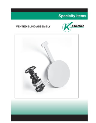
- 43. 02.2014 HEAD OFFICE: P.O. Box 999, 645 Keddco Street, Sarnia Ontario, N7T 7K6 TELEPHONE (519) 336.2960 • FAX (519) 344.3181 EDMONTON OFFICE: 4120 - 78 Avenue, Edmonton, Alberta T6B 3M8 TELEPHONE (780) 438.4944 • FAX (780) 435.3917 • T.F. 1.800.661.3809 www.keddco.com Specialty Items VENTED BLIND ASSEMBLY
- 44. 01.2014
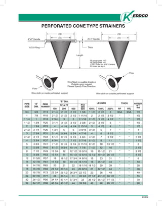
- 45. 02.2014 Head Office: P.O. Box 999, 645 Keddco Street, Sarnia, Ontario N7T 7K6 Telephone (519) 336-2960 Fax (519) 344-3181 4120 - 78 Avenue, Edmonton, Alberta T6B 3M8 Telephone (780) 438-4944 Fax (780) 435-3917 Toll Free 1-800-661-3809 www.keddco.com MFG. LTD. ISSUE-2005/10 PERFORATED CONE TYPE STRAINERS PIPE SIZE "A" DIM. RING NUMBER 150 300 2 1/2 2 1/2 3 3 1/2 4 1/4 5 5 3/4 6 1/4 7 8 1/4 9 3/4 12 14 16 1/2 19 21 23 1/4 25 1/2 30 1/4 37 1/4 43 1/2 600 2 1/2 1 3/8 1 11/16 2 1/16 2 3/8 2 13/16 3 9/16 4 7/16 4 3/4 5 7/16 6 11/16 7 7/8 10 3/16 12 5/16 14 9/16 16 1/16 18 1/16 20 9/16 22 1/2 26 5/8 33 39 3/8 2 1/2 3 3 1/2 4 1/4 5 5 3/4 6 1/4 7 1/2 9 1/4 10 1/4 12 1/2 15 1/2 17 3/4 19 1/4 22 24 26 3/4 31 37 3/4 44 100% 1 1/2 2 2 1/2 2 1/2 3 3 1/2 4 4 1/2 5 1/2 6 1/2 7 1/2 10 12 1/2 15 16 18 1/2 21 23 27 1/2 35 1/2 42 150% 2 1/2 2 1/2 3 1/2 3 1/2 4 1/2 5 6 7 8 10 12 15 1/2 19 1/2 23 25 1/2 29 32 1/2 36 43 1/2 55 1/2 66 200% 3 3 1/2 4 1/2 5 6 7 8 1/2 9 1/2 11 13 1/2 16 21 26 1/2 31 34 39 44 49 58 1/2 74 1/2 89 1/2 RF llGA llGA 1/2 1/2 1/2 1/2 1/2 1 1 1 1/2 1 1/2 2 2 1/2 3 1/2 4 1/2 6 10 20 30 40 55 70 90 " " " " " " " " " " "" " " " " " " " " " " " " " " " " " " " " " " " " " " " " RTJ "B" DIA. RF & FF RTJ 300 600 LENGTH THICK APPROX. WT. lbs 3/4 5/8 R13 2 1/4 2 1/2 2 3/4 3 1/4 4 4 3/4 5 1/4 6 1/4 6 3/4 7 1/2 8 1/2 10 3/4 13 1/4 16 17 1/2 20 21 1/2 23 3/4 28 34 1/4 40 3/4 R16 R18 R20 R23 R26 R31 R34 R37 R41 R45 R49 R53 R57 R61 R65 R69 R73 R77 R95 R98 7/8 1 1 3/8 1 3/4 2 1/4 2 3/4 3 1/4 3 3/4 4 3/4 5 5/8 7 1/2 9 3/8 11 5/8 12 7/8 14 7/8 16 7/8 18 7/8 22 7/8 28 1/2 34 1/2 1 1 1/4 1 1/2 2 2 1/2 3 3 1/2 4 5 6 8 10 12 14 16 18 20 24 30 36 16 GA plate 14 GA plate over 6” 1/8 dia. holes on 3/16 centres 33 holes per sq. in. D2 PERFORATED CONE TYPE STRAINERS PIPE SIZE “A” DIM. RING NUMBER “B” DIA. RF & FF 150 300 600 LENGTH 100% 150% 200% RTJ 300 600 THICK RF RTJ APPROX. WT. lbs B Flow Wire cloth on inside perforated support Flow Wire cloth on outside perforated support Wire Mesh is availble Inside or Outside upon request. Please Specify Flow Direction. 4"x1" Handle A.S.A Ring B A 4"x1" Handle 16 gauge plate < 6" 14 gauge plate > 6" 1/8" Holes on 3/16" Centers 33 Holes per sq.in. Length Thick A
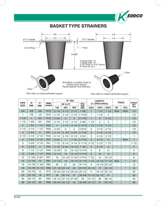
- 46. 02.2014 BASKET TYPE STRAINERS Head Office: P.O. Box 999, 645 Keddco Street, Sarnia, Ontario N7T 7K6 Telephone (519) 336-2960 Fax (519) 344-3181 4120 - 78 Avenue, Edmonton, Alberta T6B 3M8 Telephone (780) 438-4944 Fax (780) 435-3917 Toll Free 1-800-661-3809 www.keddco.com MFG. LTD. ISSUE-2005/10 BASKET TYPE STRAINERS PIPE SIZE "A" DIM. "C" DIM. RING NUMBER B DIA. LENGTH (% OPEN AREA) THICK APPROX WT. lbs. RF & FF 150 2 1/4 2 1/2 2 3/4 3 1/4 4 4 3/4 5 1/4 6 1/4 6 3/4 7 1/2 8 1/2 10 3/4 13 1/4 16 17 1/2 20 21 1/2 23 3/4 28 34 1/4 40 3/4 300 2 1/2 2 1/2 3 3 1/2 4 1/4 5 5 3/4 6 1/4 7 8 1/4 9 3/4 12 14 16 1/2 19 21 23 1/4 25 1/2 30 1/4 37 1/4 43 1/2 600 2 1/2 1 3/8 1 11/16 2 1/16 2 3/8 2 13/16 3 9/16 4 7/16 4 3/4 5 7/16 6 11/16 7 7/8 10 3/16 12 5/16 14 9/16 16 1/16 18 1/16 20 9/16 22 1/2 26 5/8 33 39 3/8 2 1/2 3 3 1/2 4 1/4 5 5 3/4 6 1/4 7 1/2 9 1/4 10 1/4 12 1/2 15 1/2 17 3/4 19 1/4 22 24 26 3/4 31 37 3/4 44 100% 1 1 1 1 1/2 1 1/2 2 3 3 3 3 1/2 4 5 6 7 1/2 7 1/2 9 10 1/2 11 13 1/2 15 1/2 18 1/2 150% 1 1/2 1 1/2 2 2 2 1/2 3 1/2 4 1/2 4 1/2 4 1/2 5 1/2 6 1/2 8 10 12 12 1/2 14 1/2 17 18 1/2 22 1/2 26 31 200% 1 1/2 2 2 1/2 3 3 1/2 4 1/2 5 1/2 5 1/2 6 7 1/2 9 11 14 16 1/2 17 1/2 20 1/2 23 1/2 25 1/2 31 36 1/2 43 1/2 RF llGA " " " " " " " " " " " " " llGA " " " " " " RTJ llGA 1/2 1/2 1/2 1/2 1/2 1/2 1/2 1 1 1 1/2 2 4 6 8 10 12 16 20 30 40 50 " " " " " " " llGA " " " " " " " " " " " " RTJ 300 600 3/4 5/8 7/8 1 1 3/8 1 3/4 2 1/4 2 3/4 3 1/4 3 3/4 4 3/4 5 5/8 7 1/2 9 3/8 11 5/8 12 7/8 14 7/8 16 7/8 18 7/8 22 7/8 28 1/2 34 1/2 3/8 1/2 3/4 3/4 1 1/4 1 1/2 2 2 1/4 2 1/2 3 1/4 4 5 1/2 7 1/4 8 3/4 10 11 3/4 13 1/2 15 18 20 26 R13 R16 R18 R20 R23 R26 R31 R34 R37 R41 R45 R49 R53 R57 R61 R65 R69 R73 R77 R95 R98 1 1 1/4 1 1/2 2 2 1/2 3 3 1/2 4 5 6 8 10 12 14 16 18 20 24 30 36 THICK 16 GA plate up to 6” 14 GA plate over 6” 1/8 dia. holes on 3/16 centres 33 holes per sq. in. D3 PIPE SIZE “A” DIM. “C” DIM. “B” DIA. RF & FF 150 300 600 LENGTH (% OPEN AREA) 100% 150% 200% RTJ 300 600 THICK RF RTJ APPROX. WT. lbs RING NUMBER B Flow Wire cloth on outside perforated support Wire Mesh is availble Inside or Outside upon request. Please Specify Flow Direction. Flow Wire cloth on inside perforated support 4"x1" Handle A.S.A Ring B A 4"x1" Handle 16 gauge plate < 6" 14 gauge plate > 6" 1/8" Holes on 3/16" Centers 33 Holes per sq.in. Thick A Length
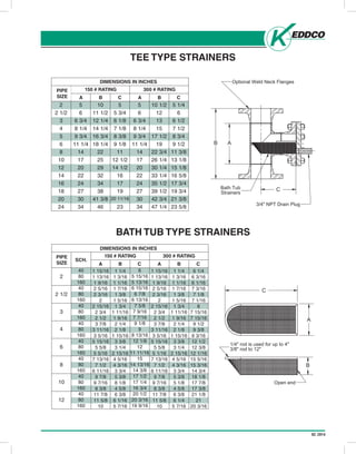
- 47. 02.2014 Head Office: P.O. Box 999, 645 Keddco Street, Sarnia, Ontario N7T 7K6 Telephone (519) 336-2960 Fax (519) 344-3181 4120 - 78 Avenue, Edmonton, Alberta T6B 3M8 Telephone (780) 438-4944 Fax (780) 435-3917 Toll Free 1-800-661-3809 www.keddco.com MFG. LTD. ISSUE-2005/10 TEE TYPE STRAINERS BATH TUB TYPE STRAINERS DIMENSIONS IN INCHES PIPE SIZE 2 2 1/2 3 4 5 6 8 10 12 14 16 18 20 24 A 5 6 6 3/4 8 1/4 9 3/4 11 1/4 14 17 20 22 24 27 30 34 B 10 11 1/2 12 1/4 14 1/4 16 3/4 18 1/4 22 25 29 32 34 38 41 3/8 46 C 5 5 3/4 6 1/8 7 1/8 8 3/8 9 1/8 11 12 1/2 14 1/2 16 17 19 20 11/16 23 A 5 6 6 3/4 8 1/4 9 3/4 11 1/4 14 17 20 22 24 27 30 34 B 10 1/2 12 13 15 17 1/2 19 22 3/4 26 1/4 30 1/4 33 1/4 35 1/2 39 1/2 42 3/4 47 1/4 C 5 1/4 6 6 1/2 7 1/2 8 3/4 9 1/2 11 3/8 13 1/8 15 1/8 16 5/8 17 3/4 19 3/4 21 3/8 23 5/8 150 # RATING 300 # RATING DIMENSIONS IN INCHES PIPE SIZE 2 2 1/2 3 4 6 8 10 12 SCH. A B C A B C 150 300 40 1 15/16 1 1/4 1 3/16 1 1/16 1 7/16 1 3/8 1 5/16 1 3/4 1 11/16 1 9/16 2 1/4 2 1/8 1 15/16 3 3/8 3 1/4 2 15/16 4 5/16 4 3/16 3 3/4 5 3/8 8 1/8 4 5/8 6 3/8 6 1/16 5 7/16 6 5 15/16 5 13/16 6 15/16 6 7/8 6 13/16 7 5/8 7 9/16 7 7/16 9 1/8 9 8 13/16 12 1/8 12 11 11/16 15 14 13/16 14 3/8 17 1/2 17 1/4 16 3/4 20 1/2 20 3/16 19 9/16 1 15/16 1 13/16 1 9/16 2 5/16 2 3/16 2 2 15/16 2 3/4 2 1/2 3 7/8 3 11/16 3 5/16 5 15/16 5 5/8 5 1/16 7 13/16 7 1/2 6 11/16 9 7/8 9 7/16 8 3/8 11 7/8 11 5/8 10 1 1/4 1 3/16 1 1/16 1 7/16 1 3/8 1 5/16 1 3/4 1 11/16 1 9/16 2 1/4 2 1/8 1 15/16 3 3/8 3 1/4 2 15/16 4 5/16 4 3/16 3 3/4 5 3/8 5 1/8 4 5/8 6 3/8 6 1/4 5 7/16 6 1/4 6 3/16 6 1/16 7 3/16 7 1/8 7 1/16 8 7 15/16 7 15/16 9 1/2 9 3/8 9 3/16 12 1/2 12 3/8 12 1/16 15 5/16 15 3/16 14 3/4 18 1/8 17 7/8 17 3/8 21 1/8 21 20 3/16 1 13/16 1 9/16 2 5/16 2 3/16 2 2 15/16 2 3/4 2 1/2 3 7/8 3 11/16 3 5/16 5 15/16 5 5/8 5 5/16 7 13/16 7 1/2 6 11/16 9 7/8 9 7/16 8 3/8 11 7/8 11 5/8 10 80 160 40 80 160 40 80 160 40 80 160 40 80 160 40 80 160 40 80 160 40 80 160 End and side rod are made of similar material. Other sizes and ratings available. D4 TEE TYPE STRAINERS PIPE SIZE BATH TUB TYPE STRAINERS DIMENSIONS IN INCHES 150 # RATING 300 # RATING A B C A B C 150 # RATING 300 # RATING A B C A B C PIPE SIZE SCH. DIMENSIONS IN INCHES C A 3/8" rod to 12" 1/4" rod is used for up to 4" Open end B Optional Weld Neck Flanges Strainers Bath Tub 3/4" NPT Drain Plug AB C
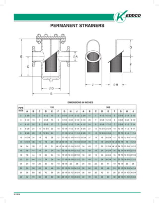
- 48. 02.2014 Head Office: P.O. Box 999, 645 Keddco Street, Sarnia, Ontario N7T 7K6 Telephone (519) 336-2960 Fax (519) 344-3181 4120 - 78 Avenue, Edmonton, Alberta T6B 3M8 Telephone (780) 438-4944 Fax (780) 435-3917 Toll Free 1-800-661-3809 www.keddco.com MFG. LTD. ISSUE-2005/10 PERMANENT STRAINERS PIPE SIZE A 2 3/8 3 1/2 4 1/2 6 5/8 8 5/8 10 3/4 12 3/4 14 16 18 20 24 30 36 42 2 3 4 6 8 10 12 14 16 18 20 24 30 36 42 B 15 18 22 24 28 34 36 39 44 44 44 49 59 69 72 C 7 7 9 12 13 14 16 17 19 19 21 22 26 30 34 D 4 1/2 6 5/8 8 5/8 10 3/4 12 3/4 16 18 20 24 24 24 30 36 42 48 E 15 15 17 22 24 26 29 31 34 34 38 40 48 56 62 F 5 5 7 10 11 12 13 1/2 14 1/2 16 16 18 19 23 26 30 G 8 1/8 8 1/8 8 1/8 10 1/8 11 1/8 12 1/8 13 1/8 14 1/8 15 1/8 15 1/8 17 1/8 18 1/8 22 1/8 26 1/8 28 1/8 H 2 1/4 3 3/4 5 1/2 7 1/2 9 1/4 12 1/4 13 15 1/4 18 1/4 18 1/4 18 1/4 22 30 1/4 35 1/2 41 1/2 J 3 1/2 5 1/2 7 1/4 9 1/4 11 1/4 14 1/2 16 1/2 18 1/2 22 1/2 22 1/2 22 1/2 28 34 1/4 39 3/4 45 3/4 A 2 3/8 3 1/2 4 1/2 6 5/8 8 5/8 10 3/4 12 3/4 14 16 18 20 24 30 36 42 B 17 20 24 27 31 37 40 43 49 49 49 50 60 69 72 C 7 7 9 12 13 14 16 17 19 19 21 22 26 30 34 D 4 1/2 6 5/8 8 5/8 10 3/4 12 3/4 16 18 20 24 24 24 30 36 42 48 E 15 1/2 15 1/2 17 1/2 22 3/4 24 3/4 26 3/4 29 3/4 31 3/4 34 3/4 34 3/4 38 3/4 41 49 57 63 F 5 5 7 10 11 12 13 1/2 14 1/2 16 16 18 19 23 26 30 G 8 5/8 8 5/8 8 5/8 10 7/8 11 7/8 12 7/8 13 7/8 14 7/8 15 7/8 15 7/8 17 7/8 19 1/8 23 1/8 27 1/8 29 1/8 H 2 1/4 3 3/4 5 1/2 7 1/2 9 1/4 12 1/4 13 15 1/4 18 1/4 18 1/4 18 1/4 22 30 1/4 35 1/2 14 1/2 J 3 1/2 5 1/2 7 1/4 9 1/4 11 1/4 14 1/2 16 1/2 18 1/2 22 1/2 22 1/2 22 1/2 28 34 1/4 39 3/4 45 3/4 150 300 DIMENSIONS IN INCHES D5 PERMANENT STRAINERS PIPE SIZE 150 300 DIMENSIONS IN INCHES AAAAAAAA B C D E F G H J A B C D E F G H J J G B C E D A H F
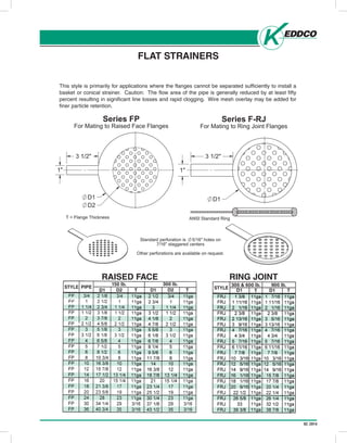
- 49. 02.2014 MFG. LTD. ISSUE-2005/10 FLAT STRAINERS This style is primarily for applications where the flanges cannot be separated sufficiently to install a basket or conical strainer. Caution: The flow area of the pipe is generally reduced by at least fifty percent resulting in significant line losses and rapid clogging. Wire mesh overlay may be added for finer particle retention. SERIES F-RJ FOR MATING TO RING JOINT FLANGES SERIES FP FOR MATING TO RAISED FACE FLANGES FLAT STRAINERS 150 lb. D1 STYLE PIPE RAISED FACE RING JOINT D2 T 300 lb. D1 D2 T STYLE 300 & 600 lb. D1 T 900 lb. D1 T D1 D2 Standard perforation is 5/16" holes on 7/16" staggered centers Other perforations are available on request. ANSI Standard Ring Series F-RJ For Mating to Ring Joint Flanges 1" 3 1/2" D1 T = Flange Thickness Series FP For Mating to Raised Face Flanges 3 1/2" 1" Head Office: P.O. Box 999, 645 Keddco Street, Sarnia, Ontario N7T 7K6 Telephone (519) 336-2960 Fax (519) 344-3181 4120 - 78 Avenue, Edmonton, Alberta T6B 3M8 Telephone (780) 438-4944 Fax (780) 435-3917 Toll Free 1-800-661-3809 www.keddco.com MFG. LTD. ISSUE-2005/10 D6 FLAT STRAINERS This style is primarily for applications where the flanges cannot be separated sufficiently to install a basket or conical strainer. Caution: The flow area of the pipe is generally reduced by at least fifty percent resulting in significant line losses and rapid clogging. Wire mesh overlay may be added for finer particle retention. SERIES F-RJ FOR MATING TO RING JOINT FLANGES SERIES FP FOR MATING TO RAISED FACE FLANGES
- 50. 02.2014 NOTES www.keddco.com SARNIA | EDMONTON | HOUSTON
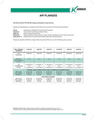
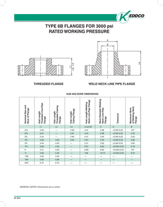
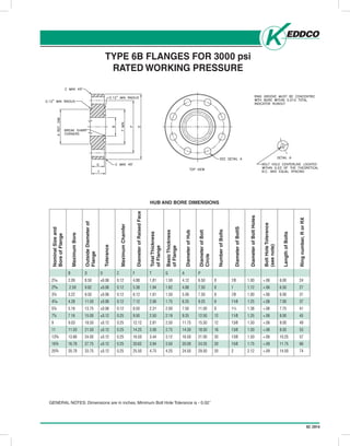
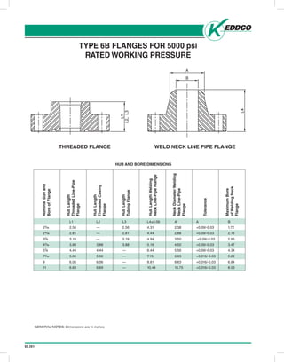
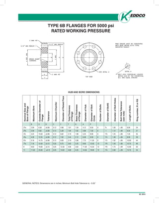
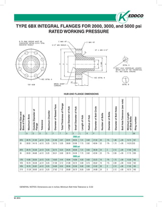
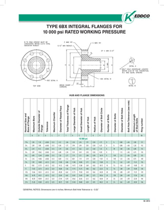
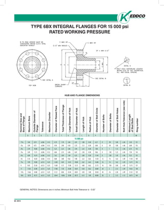
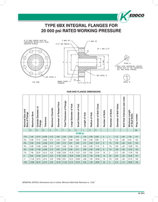
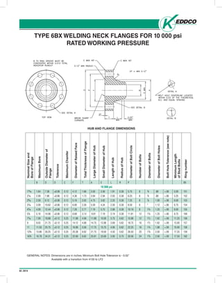
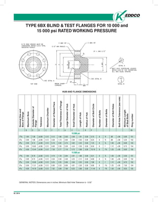
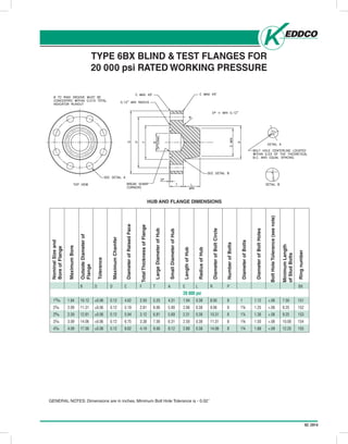
- 51. 02.2014 SECTION 4a API 6A TYPE 6B, 6BX Flanges and Studded Crosses and Tees API FLANGES Flanges and Studded Blocks are designed and manufactured in accordance with the following specifications:- API 6A Specification for Wellhead and Christmas Tree Equipment. ANSI B31.3 Chemical Plant and Petroleum Refinery Piping. ASME VIII Boiler and Pressure Vessel Code. MSS-SP-55 Quality Standards for Steel Castings for Valves, Flanges and Fittings and other Piping Components. NACE MR-01-75 Sulphide Stress Cracking Resistant Metallic Materials for Oilfield Equipment. Flanges are available as Weld Neck, Integral, Blinds, Target & Test Blinds for use with the following pressure ratings:- MAX. WORKING PRESSURE TEST PRESSURE PRODUCT SPECIFICATION LEVELS API TEMPERATURE RATING MIN.YIELD MN. TENSILE MATERIAL MIN.YIELD MIN. TENSILE MATERIAL 2,000 PSI 3,000 PSI 1,2,3 K (-60 DEG C) TO Y (+345 DEG C) 60,000 PSI 85,000 PSI API 60K 45,000 PSI 70,000 PSI API 45K 3000 PSI 4,500 PSI 1,2,3 K (-60 DEG C) TO Y (+345 DEG C) 60,000 PSI 85,000 PSI API 60K 45,000 PSI 70,000 PSI API 45K 5,000 PSI 7,500 PSI 1,2,3 K (-60 DEG C) TO Y (+345 DEG C) 60,000 PSI 85,000 PSI API 60K 45,000 PSI 70,000 PSI API 45K 10,000 PSI 15,000 PSI 1,2,3 K (-60 DEG C) TO Y (+345 DEG C) 60,000 PSI 85,000 PSI API 60K 60,000 PSI 85,000 PSI API 60K 2000 PSI 22,000 PSI 1,2,3 K (-60 DEG C) TO Y (+345 DEG C) 75,000 PSI 95,000 PSI API 75K 75,000 PSI 95,000 PSI API 75K 2000 PSI 30,000 PSI 1,2,3 K (-60 DEG C) TO Y (+345 DEG C) 75,000 PSI 95,000 PSI API 75K 75,000 PSI 95,000 PSI API 75K GENERAL NOTES: Max. working pressures stated are suitable for temperatures up to 121°C. De-rating of max. working pressure will occur as the operating temperature increases above 121°C. INTEGRAL, BLIND,TARGET BLIND & TEST FLANGES AND STUDDED BLOCKS WELD NECK FLANGES
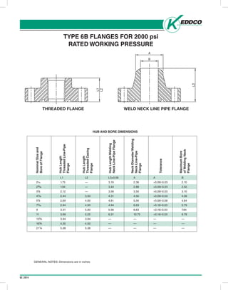
- 52. 02.2014 TYPE 6B FLANGES FOR 2000 psi RATED WORKING PRESSURE NominalSizeand BoreofFlange HUB AND BORE DIMENSIONS HubLength ThreadedLine-Pipe Flange HubLength ThreadedCasing Flange HubLengthWelding NeckLine-PipeFlange NeckDiameterWelding NeckLine-Pipe Flange Tolerance MaximumBore ofWeldingNeck Flange L1 L2 L3±0.06 A A B 21/16 1.75 — 3.19 2.38 +0.09/-0.03 2.10 29⁄16 1.94 — 3.44 2.88 +0.09/-0.03 2.50 31⁄8 2.12 — 3.56 3.50 +0.09/-0.03 3.10 41⁄16 2.44 3.50 4.31 4.50 +0.09/-0.03 4.06 51⁄8 2.69 4.00 4.81 5.56 +0.09/-0.08 4.84 71⁄16 2.94 4.50 4.94 6.63 +0.16/-0.03 5.79 9 3.31 5.00 5.56 8.63 +0.16/-0.03 7.84 11 3.69 5.25 6.31 10.75 +0.16/-0.03 9.78 135⁄8 3.94 3.94 — — — — 16¾ 4.50 4.50 — — — — 21¼ 5.38 5.38 — — — — GENERAL NOTES: Dimensions are in inches THREADED FLANGE WELD NECK LINE PIPE FLANGE
- 53. 02.2014 TYPE 6B FLANGES FOR 2000 psi RATED WORKING PRESSURE NominalSizeand BoreofFlange MaximumBore OutsideDiameterof Flange Tolerance MaximumChamfer Diameterof RaisedFace TotalThickness ofFlange DiameterofHub DiameterofBoltCircle NumberofBolts DiameterofBolts DiameterofBoltHoles BoltHoleTolerance (seenote) LengthofBolts Ringnumber,RorRX HUB AND BORE DIMENSIONS B D D C F T G A P 21⁄16 2.09 6.50 ±0.06 0.12 4.25 1.31 1.00 3.31 5.00 8 5⁄8 0.75 +.06 4.50 23 29⁄16 2.59 7.50 ±0.06 0.12 5.00 1.44 1.12 3.94 5.88 8 ¾ 0.88 +.06 5.00 26 31⁄8 3.22 8.25 ±0.06 0.12 5.75 1.56 1.25 4.62 6.62 8 ¾ 0.88 +.06 5.25 31 41⁄16 4.28 10.75 ±0.06 0.12 6.88 1.81 1.50 6.00 8.50 8 7⁄8 1.00 +.06 6.00 37 51⁄8 5.16 13.00 ±0.06 0.12 8.25 2.06 1.75 7.44 10.50 8 1 1.12 +.06 6.75 41 71⁄16 7.16 14.00 ±0.12 0.25 9.50 2.19 1.88 8.75 11.50 12 1 1.12 +.06 7.00 45 9 9.03 16.50 ±0.12 0.25 11.88 2.50 2.19 10.75 13.75 12 11⁄8 1.25 +.06 8.00 49 11 11.03 20.00 ±0.12 0.25 14.00 2.81 2.50 13.50 17.00 16 1¼ 1.38 +.06 8.75 53 135⁄8 13.66 22.00 ±0.12 0.25 16.25 2.94 2.62 15.75 19.25 20 1¼ 1.38 +.06 9.00 57 16¾ 16.78 27.00 ±0.12 0.25 20.00 3.31 3.00 19.50 23.75 20 1½ 1.62 +.09 10.25 65 21¼ 21.28 32.00 ±0.12 0.25 25.00 3.88 3.50 24.00 28.50 24 15⁄8 1.75 +.09 11.75 73 BasicThickness ofFlange GENERAL NOTES: Dimensions are in inches. Minimum Bolt Hole Tolerance is - 0.02˝
- 54. 02.2014 TYPE 6B FLANGES FOR 3000 psi RATED WORKING PRESSURE NominalSizeand BoreofFlange HUB AND BORE DIMENSIONS HubLength ThreadedLine-Pipe Flange HubLength ThreadedCasing Flange HubLengthWelding NeckLine-PipeFlange NeckDiameterWelding NeckLine-Pipe Flange Tolerance MaximumBore ofWeldingNeck Flange L1 L2 L3 L4±0.06 A A B 21⁄16 2.56 — 2.56 4.31 2.38 +0.09/-0.03 1.97 29⁄16 2.81 — 2.81 4.44 2.88 +0.09/-0.03 2.35 31⁄8 2.44 — 2.94 4.31 3.50 +0.09/-0.03 2.93 41⁄16 3.06 3.50 3.50 4.81 4.50 +0.09/-0.03 3.86 51⁄8 3.44 4.00 — 5.31 5.56 +0.09/-0.03 4.84 71⁄16 3.69 4.50 — 5.81 6.63 +0.016/-0.03 5.79 9 4.31 5.00 — 6.69 8.63 +0.016/-0.03 7.47 11 4.56 5.25 — 7.56 10.75 +0.016/-0.03 9.34 135⁄8 4.94 4.94 — — — — — 16¾ 5.06 5.69 — — — — — 20¾ 6.75 6.75 — — — — — HubLength TubingFlange THREADED FLANGE WELD NECK LINE PIPE FLANGE GENERAL NOTES: Dimensions are in inches
- 55. 02.2014 TYPE 6B FLANGES FOR 3000 psi RATED WORKING PRESSURE NominalSizeand BoreofFlange MaximumBore OutsideDiameterof Flange Tolerance MaximumChamfer DiameterofRaisedFace TotalThickness ofFlange DiameterofHub DiameterofBolt Circle NumberofBolts DiameterofBoltS DiameterofBoltHoles BoltHoleTolerance (seenote) LengthofBolts Ringnumber,RorRX HUB AND BORE DIMENSIONS B D D C F T G A P 21⁄16 2.09 8.50 ±0.06 0.12 4.88 1.81 1.50 4.12 6.50 8 7⁄8 1.00 +.06 6.00 24 29⁄16 2.59 9.62 ±0.06 0.12 5.38 1.94 1.62 4.88 7.50 8 1 1.12 +.06 6.50 27 31⁄8 3.22 9.50 ±0.06 0.12 6.12 1.81 1.50 5.00 7.50 8 7⁄8 1.00 +.06 6.00 31 41⁄16 4.28 11.50 ±0.06 0.12 7.12 2.06 1.75 6.25 9.25 8 11⁄8 1.25 +.06 7.00 37 51⁄8 5.16 13.75 ±0.06 0.12 8.50 2.31 2.00 7.50 11.00 8 1¼ 1.38 +.06 7.75 41 71⁄6 7.16 15.00 ±0.12 0.25 9.50 2.50 2.19 9.25 12.50 12 11⁄8 1.25 +.06 8.00 45 9 9.03 18.50 ±0.12 0.25 12.12 2.81 2.50 11.75 15.50 12 13⁄8 1.50 +.06 9.00 49 11 11.03 21.50 ±0.12 0.25 14.25 3.06 2.75 14.50 18.50 16 13⁄8 1.50 +.06 9.50 53 135⁄8 13.66 24.00 ±0.12 0.25 16.50 3.44 3.12 16.50 21.00 20 13⁄8 1.50 +.06 10.25 57 16¾ 16.78 27.75 ±0.12 0.25 20.62 3.94 3.50 20.00 24.25 20 15⁄8 1.75 +.09 11.75 66 20¾ 20.78 33.75 ±0.12 0.25 25.50 4.75 4.25 24.50 29.50 20 2 2.12 +.09 14.50 74 BasicThickness ofFlange GENERAL NOTES: Dimensions are in inches. Minimum Bolt Hole Tolerance is - 0.02˝
- 56. 02.2014 TYPE 6B FLANGES FOR 5000 psi RATED WORKING PRESSURE NominalSizeand BoreofFlange HUB AND BORE DIMENSIONS HubLength ThreadedLine-Pipe Flange HubLength ThreadedCasing Flange HubLengthWelding NeckLine-PipeFlange NeckDiameterWelding NeckLine-Pipe Flange Tolerance MaximumBore ofWeldingNeck Flange L1 L2 L3 L4±0.06 A A B 21⁄16 2.56 — 2.56 4.31 2.38 +0.09/-0.03 1.72 29⁄16 2.81 — 2.81 4.44 2.88 +0.09/-0.03 2.16 31⁄8 3.19 — 3.19 4.94 3.50 +0.09/-0.03 2.65 41⁄16 3.88 3.88 3.88 5.19 4.50 +0.09/-0.03 3.47 51⁄8 4.44 4.44 — 6.44 5.56 +0.09/-0.03 4.34 71⁄16 5.06 5.06 — 7.13 6.63 +0.016/-0.03 5.22 9 6.06 6.06 — 8.81 8.63 +0.016/-0.03 6.84 11 6.69 6.69 — 10.44 10.75 +0.016/-0.03 8.53 HubLength TubingFlange THREADED FLANGE WELD NECK LINE PIPE FLANGE GENERAL NOTES: Dimensions are in inches
- 57. 02.2014 TYPE 6B FLANGES FOR 5000 psi RATED WORKING PRESSURE NominalSizeand BoreofFlange MaximumBore OutsideDiameterof Flange Tolerance MaximumChamfer DiameterofRaisedFace TotalThickness ofFlange DiameterofHub DiameterofBolt Circle NumberofBolts DiameterofBoltS DiameterofBoltHoles BoltHoleTolerance (seenote) LengthofBolts Ringnumber,RorRX HUB AND BORE DIMENSIONS B D D C F T G A P 21⁄16 2.09 8.50 ±0.06 0.12 4.88 1.81 1.50 4.12 6.50 8 7⁄8 1.00 +.06 6.00 24 29⁄16 2.59 9.62 ±0.06 0.12 5.38 1.94 1.62 4.88 7.50 8 1 1.12 +.06 6.50 27 31⁄8 3.22 10.50 ±0.06 0.12 6.62 2.19 1.88 5.25 8.00 8 11⁄8 1.25 +.06 7.25 35 41⁄16 4.28 12.25 ±0.06 0.12 7.62 2.44 2.12 6.38 9.50 8 1¼ 1.38 +.06 8.00 39 51⁄8 5.16 14.75 ±0.06 0.12 9.00 3.19 2.88 7.75 11.50 8 1½ 1.62 +.06 10.00 44 71⁄16 7.16 15.50 ±0.12 0.25 9.75 3.62 3.25 9.00 12.50 12 13⁄8 1.50 +.06 10.75 46 9 9.03 19.00 ±0.12 0.25 12.50 4.06 3.62 11.50 15.50 12 15⁄8 1.75 +.09 12.00 50 11 11.03 23.00 ±0.12 0.25 14.63 4.69 4.25 14.50 19.00 12 17⁄8 2.00 +.09 13.75 54 BasicThickness ofFlange GENERAL NOTES: Dimensions are in inches. Minimum Bolt Hole Tolerance is - 0.02˝
- 58. 02.2014 TYPE 6BX INTEGRAL FLANGES FOR 2000, 3000, and 5000 psi RATED WORKING PRESSURE NominalSizeand BoreofFlange MaximumBore OutsideDiameterof Flange Tolerance MaximumChamfer DiameterofRaisedFace TotalThicknessofFlange SmallDiameterofHub LengthofHub RadiusofHub DiameterofBoltCircle NumberofBolts DiameterofBolts DiameterofBoltHoles BoltHoleTolerance(seenote) HUB AND FLANGE DIMENSIONS LargeDiameterofHub MinimumLength ofStudBolts Ringnumber B D D C F T A E L R P BX 2000 psi 26¾ 26.78 41.00 ±0.12 0.25 31.69 4.97 32.91 29.25 7.31 0.62 37.50 20 1¾ 1.88 +.09 13.75 167 30 30.03 44.19 ±0.12 0.25 35.75 5.28 36.69 32.80 7.75 0.62 40.94 32 15⁄8 1.75 +.09 14.25 3 03 3000 psi 26¾ 26.78 43.38 ±0.12 0.25 32.75 6.34 34.25 30.56 7.31 0.62 39.38 24 2 2.12 +.09 17.00 168 30 30.03 46.68 ±0.12 0.25 36.31 6.58 38.19 34.30 7.75 0.62 42.94 32 17⁄8 2.00 +.09 17.75 303 5000 psi 133⁄8 13.66 26.50 ±0.12 0.25 18.00 4.44 18.94 16.69 4.50 0.62 23.25 16 15⁄8 1.75 +.09 12.50 160 16¾ 16.78 30.38 ±0.12 0.25 21.06 5.13 21.88 20.75 3.00 0.75 26.62 16 17⁄8 2.00 +.09 14.50 162 18¾ 18.78 35.62 ±0.12 0.25 24.69 6.53 26.56 23.56 6.00 0.62 31.62 20 2 2.12 +.09 17.50 163 21¼ 21.28 39.00 ±0.12 0.25 27.62 7.12 29.88 26.75 6.50 0.69 34.88 24 2 2.12 +.09 18.75 165 GENERAL NOTES: Dimensions are in inches. Minimum Bolt Hole Tolerance is -0.02
- 59. 02.2014 GENERAL NOTES: Dimensions are in inches. Minimum Bolt Hole Tolerance is - 0.02˝ TYPE 6BX INTEGRAL FLANGES FOR 10 000 psi RATED WORKING PRESSURE NominalSizeand BoreofFlange MaximumBore OutsideDiameterof Flange Tolerance MaximumChamfer DiameterofRaisedFace TotalThicknessofFlange SmallDiameterofHub LengthofHub RadiusofHub DiameterofBoltCircle NumberofBolts DiameterofBolts DiameterofBoltHoles BoltHoleTolerance(seenote) HUB AND FLANGE DIMENSIONS LargeDiameterofHub MinimumLength ofStudBolts Ringnumber B D D C F T A E L R P BX 10 000 psi 113⁄16 1.84 7.38 ±0.06 0.12 4.12 1.66 3.50 2.56 1.91 0.38 5.75 8 ¾ 0.88 +.06 5.00 151 21⁄16 2.09 7.88 ±0.06 0.12 4.38 1.73 3.94 2.94 2.03 0.38 6.25 8 ¾ 0.88 +.06 5.20 152 29⁄16 2.59 9.12 ±0.06 0.12 5.19 2.02 4.75 3.62 2.25 0.38 7.25 8 7⁄8 1.00 +.06 6.00 153 31⁄16 3.09 10.62 ±0.06 0.12 6.00 2.30 5.59 4.34 2.50 0.38 8.50 8 1 1.12 +.06 6.75 154 41⁄16 4.09 12.44 ±0.06 0.12 7.28 2.77 7.19 5.75 2.88 0.38 10.19 8 11⁄8 1.25 +.06 8.00 155 51⁄8 5.16 14.06 ±0.06 0.12 8.69 3.12 8.81 7.19 3.19 0.38 11.81 12 11⁄8 1.25 +.06 8.75 169 71⁄16 7.09 18.88 ±0.12 0.25 11.88 4.06 11.88 10.00 3.75 0.62 15.88 12 1½ 1.62 +.09 11.25 156 9 9.03 21.75 ±0.12 0.25 14.12 4.88 14.75 12.88 3.69 0.62 18.75 16 1½ 1.62 +.09 13.00 157 11 11.03 25.75 ±0.12 0.25 16.88 5.56 17.75 15.75 4.06 0.62 22.25 16 1¾ 1.88 +.09 15.00 158 135⁄8 13.66 30.25 ±0.12 0.25 20.38 6.62 21.75 19.50 4.50 0.62 26.50 20 17⁄8 2.00 +.09 17.25 159 16¾ 16.78 34.31 ±0.12 0.25 22.69 6.62 25.81 23.69 3.00 0.75 30.56 24 17⁄8 2.00 +.09 17.50 162 18¾ 18.78 40.94 ±0.12 0.25 27.44 8.78 29.62 26.56 6.12 0.62 36.44 24 2¼ 2.38 +.09 22.50 164 21¼ 21.28 45.00 ±0.12 0.25 30.75 9.50 33.38 30.00 6.50 0.81 40.25 24 2½ 2.62 +.09 24.50 166
- 60. 02.2014 TYPE 6BX INTEGRAL FLANGES FOR 15 000 psi RATED WORKING PRESSURE NominalSizeand BoreofFlange MaximumBore OutsideDiameterof Flange Tolerance MaximumChamfer DiameterofRaisedFace TotalThicknessofFlange SmallDiameterofHub LengthofHub RadiusofHub DiameterofBoltCircle NumberofBolts DiameterofBolts DiameterofBoltHoles BoltHoleTolerance(seenote) HUB AND FLANGE DIMENSIONS LargeDiameterofHub MinimumLength ofStudBolts Ringnumber B D D C F T A E L R P BX 15 000 psi 113⁄16 1.84 8.19 ±0.06 0.12 4.19 1.78 3.84 2.81 1.88 0.38 6.31 8 7⁄8 1.00 +.06 5.50 151 21⁄16 2.09 8.75 ±0.06 0.12 4.50 2.00 4.38 3.25 2.12 0.38 6.88 8 7⁄8 1.00 +.06 6.00 152 29⁄16 2.59 10.00 ±0.06 0.12 5.25 2.25 5.06 3.94 2.25 0.38 7.88 8 1 1.12 +.06 6.75 153 31⁄16 3.09 11.31 ±0.06 0.12 6.06 2.53 6.06 4.81 2.50 0.38 9.06 8 11⁄8 1.25 +.06 7.50 154 41⁄16 4.09 14.19 ±0.06 0.12 7.62 3.09 7.69 6.25 2.88 0.38 11.44 8 13⁄8 1.50 +.06 9.25 155 51⁄8 5.16 16.50 ±0.06 0.12 8.88 3.88 9.62 7.88 3.22 0.62 13.50 12 1½ 1.62 +.09 11.50 169 71⁄16 7.09 19.88 ±0.12 0.25 12.00 4.69 12.81 10.88 2.62 0.62 16.88 16 1½ 1.62 +.09 12.75 156 9 9.03 25.50 ±0.12 0.25 15.00 5.75 17.00 13.75 4.88 0.62 21.75 16 17⁄8 2.00 +.09 15.75 157 11 11.03 32.00 ±0.12 0.25 17.88 7.38 23.00 16.81 9.28 0.62 28.00 20 2 2.12 +.09 19.25 158 135⁄8 13.66 34.88 ±0.12 0.25 21.31 8.06 23.44 20.81 4.50 1.00 30.38 20 2¼ 2.38 +.09 21.25 159 18¾ 18.78 45.75 ±0.12 0.25 28.44 10.06 32.00 28.75 6.12 1.00 40.00 20 3 3.12 +.12 26.75 164 GENERAL NOTES: Dimensions are in inches. Minimum Bolt Hole Tolerance is - 0.02˝
- 61. 02.2014 GENERAL NOTES: Dimensions are in inches. Minimum Bolt Hole Tolerance is - 0.02˝ TYPE 6BX INTEGRAL FLANGES FOR 20 000 psi RATED WORKING PRESSURE NominalSizeand BoreofFlange MaximumBore OutsideDiameterof Flange Tolerance MaximumChamfer DiameterofRaisedFace TotalThicknessofFlange SmallDiameterofHub LengthofHub RadiusofHub DiameterofBoltCircle NumberofBolts DiameterofBolts DiameterofBoltHoles BoltHoleTolerance(seenote) HUB AND FLANGE DIMENSIONS LargeDiameterofHub MinimumLength ofStudBolts Ringnumber B D D C F T A E L R P BX 20 000 psi 113⁄16 1.84 10.12 ±0.06 0.12 4.62 2.50 5.25 4.31 1.94 0.38 8.00 8 1 1.12 +.06 7.50 151 21⁄16 2.09 11.31 ±0.06 0.12 5.19 2.81 6.06 5.00 2.06 0.38 9.06 8 11⁄8 1.25 +.06 8.25 152 29⁄16 2.59 12.81 ±0.06 0.12 5.94 3.12 6.81 5.69 2.31 0.38 10.31 8 1¼ 1.38 +.06 9.25 153 31⁄16 3.09 14.06 ±0.06 0.12 6.75 3.38 7.56 6.31 2.50 0.38 11.31 8 13⁄8 1.50 +.06 10.00 154 41⁄16 4.09 17.56 ±0.06 0.12 8.62 4.19 9.56 8.12 2.88 0.38 14.06 8 1¾ 1.88 +.09 12.25 155 71⁄16 7.09 25.81 ±0.12 0.25 13.88 6.50 15.19 13.31 3.81 0.62 21.81 16 2 2.12 +.09 17.50 156 9 9.03 31.69 ±0.12 0.25 17.38 8.06 18.94 16.88 4.25 1.00 27.00 16 2½ 2.62 +.09 22.38 157 11 11.03 34.75 ±0.12 0.25 19.88 8.81 22.31 20.00 4.06 1.00 29.50 16 2¾ 2.88 +.09 23.75 158 135⁄8 13.66 45.75 ±0.12 0.25 24.19 11.50 27.31 24.75 5.25 1.00 40.00 20 3 3.12 +.12 30.00 159
- 62. 02.2014 TYPE 6BX WELDING NECK FLANGES FOR 10 000 psi RATED WORKING PRESSURE NominalSizeand BoreofFlange MaximumBore OutsideDiameterof Flange Tolerance MaximumChamfer DiameterofRaisedFace TotalThicknessofFlange SmallDiameterofHub LengthofHub RadiusofHub DiameterofBoltCircle NumberofBolts DiameterofBolts DiameterofBoltHoles BoltHoleTolerance(seenote) HUB AND FLANGE DIMENSIONS LargeDiameterofHub MinimumLength ofStudBolts Ringnumber B D D C F T A E L R P BX 10 000 psi 113⁄16 1.84 7.38 ±0.06 0.12 4.12 1.66 3.50 2.56 1.91 0.38 5.75 8 ¾ .88 +.06 5.00 151 21⁄16 2.09 7.88 ±0.06 0.12 4.38 1.73 3.94 2.94 2.03 0.38 6.25 8 ¾ .88 +.06 5.25 152 29⁄16 2.59 9.12 ±0.06 0.12 5.19 2.02 4.75 3.62 2.25 0.38 7.25 8 7⁄8 1.00 +.06 6.00 153 31⁄16 3.09 10.62 ±0.06 0.12 6.00 2.30 5.59 4.34 2.50 0.38 8.50 8 1 1.12 +.06 6.75 154 41⁄16 4.09 12.44 ±0.06 0.12 7.28 2.77 7.19 5.75 2.88 0.38 10.19 8 11⁄8 1.25 +.06 8.00 155 51⁄8 5.16 14.06 ±0.06 0.12 8.69 3.13 8.81 7.19 3.19 0.38 11.81 12 11⁄8 1.25 +.06 8.75 169 71⁄16 7.09 18.88 ±0.12 0.25 11.88 4.06 11.88 10.00 3.75 0.62 15.88 12 1½ 1.62 +.09 11.25 156 9 9.03 21.75 ±0.12 0.25 14.12 4.88 14.75 12.88 3.69 0.62 18.75 16 1½ 1.62 +.09 13.00 157 11 11.03 25.75 ±0.12 0.25 16.88 5.56 17.75 15.75 4.06 0.62 22.25 16 1¾ 1.88 +.09 15.00 158 135⁄8 13.66 30.25 ±0.12 0.25 20.38 6.62 21.75 19.50 4.50 0.62 26.50 20 17⁄8 2.00 +.09 17.25 159 16¾ 16.78 34.31 ±0.12 0.25 22.69 6.62 25.81 23.69 3.00 0.75 30.56 24 17⁄8 2.00 +.09 17.50 162 GENERAL NOTES: Dimensions are in inches. Minimum Bolt Hole Tolerance is - 0.02˝ Available with a transition from 4130 to LF2
- 63. 02.2014 TYPE 6BX WELDING NECK FLANGES FOR 15 000 and 20 000 psi RATED WORKING PRESSURE NominalSizeand BoreofFlange MaximumBore OutsideDiameterof Flange Tolerance MaximumChamfer DiameterofRaisedFace TotalThicknessofFlange SmallDiameterofHub LengthofHub RadiusofHub DiameterofBoltCircle NumberofBolts DiameterofBolts DiameterofBoltHoles BoltHoleTolerance(seenote) HUB AND FLANGE DIMENSIONS LargeDiameterofHub MinimumLength ofStudBolts Ringnumber B D D C F T A E L R P BX 15 000 psi 113⁄16 1.84 8.19 ±0.06 0.12 4.19 1.78 3.84 2.81 1.88 0.38 6.31 8 7⁄8 1.00 +.06 5.50 151 21⁄16 2.09 8.75 ±0.06 0.12 4.50 2.00 4.38 3.25 2.12 0.38 6.88 8 7⁄8 1.00 +.06 6.00 152 29⁄16 2.59 10.00 ±0.06 0.12 5.25 2.25 5.06 3.94 2.25 0.38 7.88 8 1 1.12 +.06 6.75 153 31⁄16 3.09 11.31 ±0.06 0.12 6.06 2.53 6.06 4.81 2.50 0.38 9.06 8 11⁄8 1.25 +.06 7.50 154 41⁄16 4.09 14.19 ±0.06 0.12 7.62 3.09 7.69 6.25 2.88 0.38 11.44 8 13⁄8 1.50 +.06 9.25 155 51⁄8 5.16 16.50 ±0.06 0.12 8.88 3.88 9.62 7.88 3.22 0.62 13.50 12 1½ 1.62 +.09 11.50 169 71⁄16 7.09 19.88 ±0.12 0.25 12.00 4.69 12.81 10.88 3.62 0.62 16.88 16 1½ 1.62 +.09 12.75 156 20 000 psi 113⁄16 1.84 10.12 ±0.06 0.12 4.62 2.50 5.25 4.31 1.94 0.38 8.00 8 1 1.12 +.06 7.50 151 21⁄16 2.09 11.31 ±0.06 0.12 5.19 2.81 6.06 5.00 2.06 0.38 9.06 8 11⁄8 1.25 +.06 8.25 152 29⁄16 2.59 12.81 ±0.06 0.12 5.94 3.12 6.81 5.69 2.31 0.38 10.31 8 1¼ 1.38 +.06 9.25 153 31⁄16 3.09 14.06 ±0.06 0.12 6.75 3.38 7.56 6.31 2.50 0.38 11.31 8 13⁄8 1.50 +.06 10.00 154 41⁄16 4.09 17.56 ±0.06 0.12 8.62 4.19 9.56 8.12 2.88 0.38 14.06 8 1¾ 1.88 +.09 12.25 155 71⁄16 7.09 25.81 ±0.12 0.25 13.88 6.50 15.19 13.31 3.81 0.62 21.81 16 2 2.12 +.09 17.50 156 GENERAL NOTES: Dimensions are in inches. Minimum Bolt Hole Tolerance is - 0.02˝ Available with a transition from 4130 to LF2
