CCNA- Router on stick, VLAN and Trunking
•Download as DOCX, PDF•
1 like•615 views
This document discusses configuring VLAN trunking and routing on a stick between two switches and a router. It explains that VLAN trunking is used to separate broadcast domains and transmit VLAN traffic between switches and routers. The trunk ports between the switches and the switch to router link are configured, as well as subinterfaces on the router with different IP addresses for each VLAN. The configuration of the switches and router is shown, along with ping tests verifying connectivity between hosts in different VLANs works after routing is configured.
Report
Share
Related slideshows

CCNA- Router on stick, VLAN and Trunking
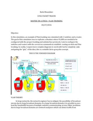
- 1. Rafat Khandaker CCNA PACKET TRACER ROUTER ON A STICK + VLAN TRUNKING 04/27/2016 Objective: In this simulation, an example of Vlan trunking was simulated with 2 switches and a router. The goal of this simulation was to replicate a situation where VLANS are needed to be configured with the proper trunking and subinterface protocols. I aim to configure the switches and routers with the correct ios commands to establish: routing on stick and Vlan trunking. In reality, I expect more complex diagrams to work with but for simplicity sake and geting the "gist," of the idea; this is a suitable lab to grasp the concept. THIS IS THE FINISHED DIAGRAM VLAN THEORY: In large networks, the network engineer has to mitigate the possibility of broadcast storms due to large broadcast domains. In a large broadcast domain, it is possible to over- load the bandwidth because of multiple switches communicating at once. Other problems due to large broadcast domains are network analyzers which can detect traffic from
- 2. multiple stations at once, which can be a security issue as well. To solve these problems, VLANS is a protocol established to separate network broadcast traffic. VLANS are usually also configured with a router because routers are designed to separate broadcast traffic. In order to pass this communications between routers and switches, the "Router on a stick" configuration is used to communicate VLAN traffic between routers and switches. THE PLAN: TRUNKING: Trunking is the link between switches to switches and switches to router, where the VLAN information can be transmitted. This is important because switches need to agree on which vlan packets are being transmitted and recieved from switch to switch. Without this configuration, VLAN information cannot be transmitted and switches will not understand how to filter traffic based VLAN configuration. The ports between switches and switch to router need to be configured with Trunk: switch0 fa(0/1) | switch1 fa(0/1) | switch1 (1/1) command: #(config-t) switchport mode trunk Each fast ethernet interface with different vlan configuration needs to be configured with different ip address switch0 ( VLAN 1 = 192.168.1.253 VLAN 10 = 192.168.10.253 VLAN 20 = 192.168.20.253 ) switch 1 ( VLAN 1 = 192.168.1.254 VLAN 10= 192.168.10.254 VLAN 20=192.168.20.254 ) ROUTER ON A STICK: Router on a stick is a sub interface configuration, where one port can be "virtually," split into multiple ports along with different ip addresses, configured with different subnets. On a router, broadcast domains are separated by subnetworks; so Vlans are usually assigned to a different subnetwork. Router 0 Subinterf ( Fa0/0 = 192.168.1.1 Fa0/0.1=192.168.10.1 Fa0/0.2=192.168.20.1)
- 3. each host belongs to the same subnetwork of their respected VLAN membership, default gateway. PC0 (VLAN 10) IP: 192.168.10.3 PC1 (VLAN 20) IP: 192.168.20.3 PC2 (VLAN 10) IP: 192.168.10.2 PC3 (VLAN 20) IP: 192.168.20.2 Lab0 (Native) IP: 192.168.1.2 Lab1 (Native) IP: 192.168.1.3 IOS CONFIGURATION SWITCH 0
- 4. SWITCH 1
- 6. ROUTER 0
- 8. PINGS FROM PC 0
- 10. In here, we can see that all pings were unsuccessful except for the host connected in the same vlan 10 as pc0, which was pc 2. This is because routing on the router has not been configured. In order for hosts to communicate with hosts on a separate VLAN, a router is needed to be configured to route traffic between hosts. We can also see, using the arp -a command, the arp table shows only hosts with layer 2 address; which can only be communicated through switch and ports configured with the same VLAN. I also tested the ping to default gateway to ensure the subinterface on fa0/0.1. Pings from Lab1
- 11. Pings from PC 1
- 12. CONCLUSION I have successfully created, configured and tested this network for VLAN configuration. I have successfully configured trunk links with proper configuration between switch to switch. I have successfully configured sub interface links between routers and switches to communicate VLAN information.