chter 3 actuators.pdffejvrvfdvkceckevsvd
•
0 likes•16 views
- Hydraulic actuators like cylinders are used to convert fluid pressure into mechanical motion or force. Single-acting cylinders produce force in one direction while double-acting cylinders can produce force in both directions. - Directional control valves include check valves, two/four-way valves, and shuttle valves. They control the direction of fluid flow. Pressure control valves like relief valves limit system pressure while flow control valves regulate fluid flow rate and actuator speed. - Properly selecting and using hydraulic components like actuators, valves, and linkages allows fluid power systems to efficiently control mechanical processes.
Report
Share


chter 3 actuators.pdffejvrvfdvkceckevsvd
- 1. WALLAGA UNIVERSITY COLLEGE OF ENGINEERING AND TECHNOLOGY DEPT : MENG COURSE:FLUID POWER SYSTEM DATE :NOV,2023
- 2. Chapter-3 Fluid power Actuators and pressurization Regulation Objectives ✓Define hydraulic actuators ✓Understanding flow control valves ✓Understanding pressure control valves and its working principle ✓Defining direction control valve and its mechanism
- 3. Fluid power Actuators ❖An actuator is used to convert the energy of fluid back into the mechanical power. ❖The amount of output power developed depends upon the flow rate, the pressure drop across the actuator and its overall efficiency. ❖Thus, hydraulic actuators are devices used to convert pressure energy of the fluid into mechanical energy motion it produces can be either rotary or linear.
- 4. Cont.... • Hydraulic cylinder extend and retract a piston rod to provide a pull or push force to drive the external load along straight path. • The function of a Hydraulic cylinder is to convert the hydraulic power into linear mechanical force or motion. Cont.... Fig.1 Hydraulic cylinder.
- 5. Types of Hydraulic Cylinders Hydraulic cylinders are of the following types: 1. Single-Acting Cylinders 2. Double-Acting Cylinders Single-Acting Actuating Cylinder ✓It produce force only in one direction by hydraulic pressure acting on the piston. ✓The return of the spring not done hydraulically ,it is either done by gravity or spring. Fig.2 single acting cylinder.
- 6. Double-Acting Cylinders • A double acting cylinder with piston on both sides is a cylinder with a rod extending from both ends. • The application involves in a process where work can be done by both the ends of cylinder, thereby making the cylinder more productive. • It can withstand higher side loads. Fig.3 double acting cylinder.
- 7. Cylinder mounting • Various cylinder mounting are widely used. • Main function to anchor the cylinder. • Mounting methods include tie rod, bolt mount,flange,trunnion,sidelugand side tapped, and clevis. • tie rod is the most common Fig.4 cylinder mounting.
- 8. • Mechanical linkages can transform a linear motion into oscillating or rotary motion. • It provide to increase or decrease the effective leverage and stroke of cylinder. • The universal alignment of mounting accessory designed to reduce misalignment problems. Mechanical linkages Fig .5 mechanical linkages
- 9. CONTROL COMPONENTS Three basic types of control devices: ❑ Directional flow valves(control fluid path) ✓ Check valves, ✓ shuttle valves, ✓ 2-way valves,3-way valves and ✓ 4-way valves DCV. ❑ pressure control valves (protect system) ❑ Flow control valves (speed control)
- 10. 1. Directional flow valves Directional control valves perform only three functions: • stop fluid flow • allow fluid flow, and • change direction of fluid flow a.Check valve Fig.6 check valve.
- 11. Cont… • A check valve allows flow in one direction, but blocks the flow in the opposite direction. • It is a two-way valve because it contains two ports. Figure.below shows the graphical symbol of a check valve along with its no-flow and free-flow directions.
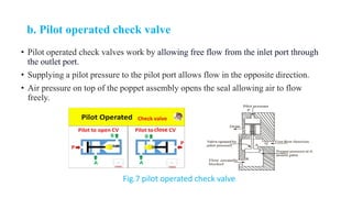
- 12. b. Pilot operated check valve • Pilot operated check valves work by allowing free flow from the inlet port through the outlet port. • Supplying a pilot pressure to the pilot port allows flow in the opposite direction. • Air pressure on top of the poppet assembly opens the seal allowing air to flow freely. Fig.7 pilot operated check valve.
- 13. Cont… c.two-way, four-way valves ✓It is used to allow inlet flow either of two outlet ports and control double acting actuators. ✓Use sliding spool to control flow by 2/3 position. Fig.8 two-way, four-way valves.
- 14. Cont………. Fig.9 two-way, four-way valves. two-way Four -way
- 15. Cont.... A two-way valves • It is sliding spool, directional-control valve. As the spool moves back and forth, it either allows or prevents fluid flow through the valve. A four-way valves • Are capable of controlling double-acting cylinders and bidirectional motors. A spool of DCV can be positioned by: ❖Manually ❖Mechanically ❖Using pilot pressure ❖Using electrical solenoid
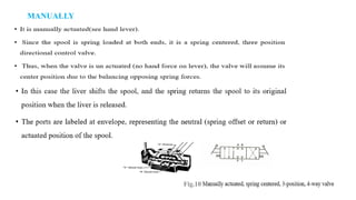
- 16. MANUALLY Fig.10 wo-way, four-way valves
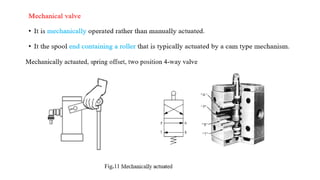
- 17. Fig.11
- 18. Fig.12
- 19. Fig.12 CENTER FLOW PATH CONFIGURATION
- 20. Fig.13 solenoid to shift spool
- 21. Fig.14 solenoid actuated valve
- 22. d.shuttle valve • It allows a system to operate from either of two fluid power sources • One application for safety when the main pump can no longer provide hydraulic power to operate emergency device • The shuttle valve will shift to allow fluid to flow from secondary backup pump. Fig.15 shuttle valves.
- 23. 2.Pressure control valve • Its primary function is to limit the system pressure . • It is found in practically all hydraulic system. • It is normally a closed valve whose function is to limit the pressure to a specified maximum value by diverting pump flow back to the tank.
- 24. Direct type relief valve • It has two basic working port connection. One port connected to pump and the other to tank. • The valve consists of control chamber with adjustable bias spring which pushes the poppet to its seat, closing the valve. • The system pressure opposes the poppet, which is maximum pressure that can be attained within the system. • The poppet is held in position by spring force and when pressure exceed this force ,the poppet is forced off its seat • This permit fluid flow back to the tank as high pressure is takes place.
- 26. Pressure reducing valve • It is used to limit its outlet pressure in hydraulic system. • The valve operates on the principle that pilot pressure from the controlled pressure side opposes an adjustable bias spring normally holding the valve open. • When two forces are equal ,the pressure downstream is controlled at pressure setting. • if spring has greater force ,the valves opens wider and if controlled pressure has greater force ,the valves moves towards the spring to control the flow pressure.
- 27. Cont... Fig.17 pressure reducing valves.
- 28. Unloading valve •Used to allow a pump to operate at minimum load. •It operates on the principle that the pump delivery is diverted to the tank. • Hence, pump has no load it develop minimum amount of power. Fig.18 unloading valve.
- 29. Sequence valve • Its primary function is to divert flow in a predetermined sequence. • It used to control the operational cycle of machine automatically. Fig.19 sequence valve.
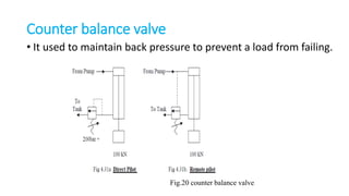
- 30. Counter balance valve • It used to maintain back pressure to prevent a load from failing. Fig.20 counter balance valve.
- 31. Cont.. • Let piston area ,𝐴𝑝 = 100 cm 2=0.01 m2 • Ring area ,𝐴𝑅 =50 cm 2=0.005 m2 • Load ,F = 100 KN • the pressure to support the load is: • p=F/𝐴𝑅 =10000/0.005=2*106 N/ m2 • =200 bar ,hence 200 bar is needed to support the load. • If pilot pressure taken directly as shown in fig.a counter valve should open at 200 bar because of inertia and friction. •
- 32. 3.Flow control valves •It control the rate of flow of a fluid through a hydraulic circuit. • Their function is to provide velocity control of linear actuators, or speed control of rotary actuators.
- 33. Functions of Flow-Control Valves 1. .Regulate the speed of linear and rotary actuators: 2.Regulate the power available to the sub-circuits by controlling the flow to them: 3.Proportionally divide or regulate the pump flow to various branches of the circuit:
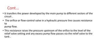
- 34. Cont... • It transfers the power developed by the main pump to different sectors of the circuit . • The orifice or flow-control valve in a hydraulic pressure line causes resistance to pump flow. • This resistance raises the pressure upstream of the orifice to the level of the relief valve setting and any excess pump flow passes via the relief valve to the tank .
- 35. factors that determine the flow rate(Q) across an orifice 1.Cross-sectional area of orifice. 2. Shape of the orifice (round, square or triangular). 3. Length of the restriction. 4. Pressure difference across the orifice (Δp). 5. Viscosity of the fluid. Fig.21simple restrictor-type flow-control valves Thus, the law that governs the flow rate across a given orifice can be approximately defined as: 𝑄2 p
- 36. Cont...... • This implies that any variation in the pressure upstream or downstream of the orifice changes the pressure differential Δp and thus the flow rate through the orifice (Fig.below) Fig.22 .Variation of flow rate with pressure drop
- 37. Compensation type flow control valve • Flow-control valves can be classified as follows: 1. Non-pressure compensated. 2. Pressure compensated 1. Non-pressure compensated ✓ It is used when the system pressure is relatively constant and motoring speeds are not too critical. ✓The flow rate depends on work load hence, the variation in pressure occurs at the outlet that is defined by the work load.
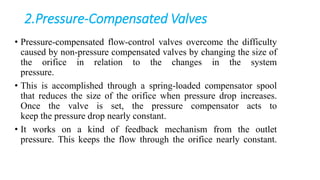
- 38. 2.Pressure-Compensated Valves • Pressure-compensated flow-control valves overcome the difficulty caused by non-pressure compensated valves by changing the size of the orifice in relation to the changes in the system pressure. • This is accomplished through a spring-loaded compensator spool that reduces the size of the orifice when pressure drop increases. Once the valve is set, the pressure compensator acts to keep the pressure drop nearly constant. • It works on a kind of feedback mechanism from the outlet pressure. This keeps the flow through the orifice nearly constant.
- 39. END