Construction of 500 MW Steam Boiler
•Download as PPTX, PDF•
18 likes•8,258 views

It is the Construction of 500 MW Subcritical Boiler. as well as the Steam cycle flow and water cycle flow of a Boiler
Report
Share


Construction of 500 MW Steam Boiler
- 1. Construction of 500 mw boiler by Vaibhav G. Paydelwar ( Project Engineer) Sunil Hi-Tech Engineers Limited
- 2. WHAT DO YOU MEAN BY BOILER ? Boiler means any closed vessel exceeding 22.75 Ltr. in capacity used for steam generation under pressure. The first boiler was developed in 1725 and its working pressure was 10 kg/ cm2. Boiler can be regarded as a number of interconnected heat exchangers arranged in such manner that heat available by burning of fuel is transferred to convert water into steam in most efficient manner.
- 3. FUNCTION OF BOILER To produce the steam at the desired rate at desired pressure and temperature with use of resources such as oil, coal & water for generating the power.
- 4. Types of Boilers Natural circulation Boiler :Drum to down comer - to main ring header – to ww tubes and back -to drum. Due to difference in density of water and steam this types of circulation takes place. Forced circulation (Assisted circulation) Boiler :As per operating pressure of the boiler approaches to the critical pressure, additional pumps are required to install in down comers, because at this pressure there is no appreciable density difference between water and steam to have natural circulation of water.
- 5. NEED FOR ASSISTED CIRCULATION 0.7 Density of Water 0.6 0.5 0.4 Critical Point 0.3 0.2 0.1 Density of Steam 0 80 100 120 140 160 180 Pressure (Kg/cm2) 200 220 240
- 6. According to working pressure Sub critical pressure boiler : when working pressure of boiler is between 130 to 180 kg/ cm2 critical boiler : when working pressure of boiler is 225.56 kg/ cm2 Super critical boiler : when working pressure of boiler is 240.10 kg/ cm2
- 7. Why to go for higher capacity ? 1’-2’ = Work done in turbine from P1 – P2 2’-3 = Heat Rejection in condenser 3-4 = Water pumped to boiler 4-1 = Heat addition in eco and boiler.
- 8. SPECIAL FEATURES OF 500MW BOILER Controlled circulation of feed water in water walls with the help of 3 Nos. of boiler circulating water pumps installed on down comers. Rifled bore water wall tubes as against smooth bore tubes in 210 MW boiler. Provision of Orifices for equal distribution of water in water wall tubes from bottom ring header. All down comers are connected to front header of the bottom ring header.
- 9. DESIGN FACTOR For the construction of boiler parts subjected to pressure and their integral attachment, the designer takes into account several factors Relative Cost Mechanical Properties Manufacturing Method Scaling Resistance Maintenance
- 10. Various parts of Boiler BOILER IS DIVIDED INTO TWO PASS: FIRST PASS SECOND PASS First pass of the boiler consists of:- Furnace water wall. Divisional super heater pendent assembly. Final Super heater pendent assembly. Reheater front pendent assembly. (CRH) Reheater rear pendent assembly. (HRH) Rear Arch Panel. Water Wall screen tubes.
- 11. Second pass of the boiler consists of: Steam cooled wall. Economizer lower bank coils. Economizer middle bank coils. Economizer upper bank coils. LTSH lower bank coils LTSH upper bank coils Eco. Hanger tubes. LTSH terminal tubes.
- 12. ECONOMISER Requirement why ? Advantages • • As the economiser recover the heat in the flue gas that leaves the boiler and transfer to working fluid there will be saving in fuel consumption. As the feed water is preheated in the economiser and enter the boiler tube at an elevated temperature( near to saturation temp.) the heat transfer area required for the evaporation surface required will be reduce considerably. As the size of boiler also will be reduced. Types of Economiser Steaming Non steaming • Plain tube economiser • Fin-tube economiser
- 13. Plain tubes Direction of Gas Flow Direction of Gas Flow Inline Arrangement Staggered Arrangement
- 15. Tube size and spacing The tubes can be made any length and diameter with 38mm to 52mm OD. The side spacing and back spacing can be arranged for good cleaning, absorption of heat and less draught loss. Spacing about 90mm to 140mm. It is composed of three banks of 130 parallel tube elements arranged in horizontal rows in such a manner that each row is in line with the row above and below.
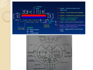
- 16. Drum & Drum Internals Requirement Separation of saturated steam from the steam-water mixture produced by the evaporating tubes Mixing feed water from economiser and water separated from steam – water mixture, and re-circulate through the evaporating tubes. Carrying out blow down for reduction of boiler water salt concentration. Treatment of Boiler water by chemicals construction of drum 1 11 111
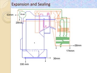
- 17. BOILER DRUM: Construction: Fusion welded Material specification: SA299 Design pressure: 204.9 kg/cm2 Maximum operating press: 193 kg/cm2 Thickness for straight portion: 195/165 mm Overall length of drum : 22070 mm Outside dia. Of Drum : 2138 mm Internal dia. Of Drum :1778 mm Elevation of drum centre above ground level: 71.583 meter No. of distribution headers : 6 No. of cyclonic separator :92 No. of secondary dryers : 92 No. of final dryers : 124 Maximum permissible DT between any two parts of Drum : 50 0C
- 18. Connection to Boiler Drum • • • • • • • • • • • Main connection Feed lines Down comers Up risers Super heater supply tubes Auxiliary connection Blow down line Chemical dosing line Instrumentation tapping Air vents Safety valves Nitrogen filling line High and low level trips
- 20. Drum Internals Feed header Anti vortex spider Steam separator Steam dryers or scrubbers C.B.D. line E.B.D. line chemical dosing line
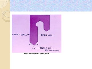
- 22. Water Walled Furnace Requirement Advantages In furnace not only combustion but also heat transfer is taking place simultaneously. The maintenance work involved in repairing the firebricks (which is otherwise necessary) is completely eliminated. Due to heat transfer in the furnace, temperature of the flue gas leaving the furnace is reduced to the acceptable level of the superheating surfaces. Higher heat loading in the furnace is possible, as heat is being simultaneously removed by heat transfer, and hence economy in surfacing. Providing a Gas tight seal to the combustion chamber to prevent air infiltration.
- 23. Water Wall Furnace Constuction
- 26. Buckstay and Furnace Guides
- 27. Superheaters Requirement? By increasing the temperature of the steam, the useful energy that can be recovered economically increases thus the efficiency of the cycle also as can be seen in Fig.3.40. Superheating of steam eliminates the condensation of steam during transporting of steam in pipelines and inside the early stages of turbines which is harmful to the turbine blades and pipe lines. Limits the work done by turbine stages to avoid excessive erosion of blades
- 28. Types of superheater radiant superheater convective superheater
- 29. Relationship in SH Design The steam temperature desired The super heater surface area required The rate of steam flow through the tubes (mass flow) The material best suited for the super heater tubes The gas temperature zones where the surfaces are to be located The arrangement of surfaces to meet the characteristics of the fuel to be used with specific reference to the spacing of tubes
- 30. Material for SH ASME CODE NOMINAL TEMP.LIMIT 0C COMPOSITION SA 213 CARBON STEEL 450 SA 213 T1 C-1/2 Mo. 470 SA 213 T11 11/4 Cr. –1/2 Mo. 550 SA 213 T22 21/4 Cr.-1 Mo. 580 SA 213 T9 9 Cr.-1 Mo. 635 SA 213 TP 304 H 18 Cr.-8 Ni. 705 SA 213 TP 347 H 18 Cr.-10 Ni. 705 SA 213 TP 316 H 16 Cr.-12 Ni.-2 Mo. 705 Description Tube Size Material Radiant Roof Tubes i. ii. Ø 63.5 X 6.3 Ø 57 X 5.6 SA 213, T11 SA 213, T11 wall i. ii. iii. Ø 63.5 X 6.3 Ø 51 X 5 Ø 76.1 X 10 SA 210, Gr C SA 210, Gr C SA 210, Gr C Steam Cooled front wall tubes i. ii. iii. Ø 51 X 5 Ø 63.5 X 6.3 Ø 44.5 X 7.1 SA 210, Gr C SA 210, Gr C SA 210, Gr C Front Wall Hanger Tubes Ø 51 X 5.0 SA 210, Gr C Rear Roof Tubes i. ii. SA 210, Gr C SA 210, Gr C Steam tubes Cooled Eco and tubes Side LTSH Support Ø 51 X 5 Ø 44.5 X 7.1 Ø 47.63 X 8.6 SA 210, Gr C
- 31. Description Tube Size Material Steam Cooled Side Wall tubes Ø 51 X 5 SA 210, Gr C Bifurcate Tubes (Bottom Header) Ø 51 X 5 SA 210, Gr C LTSH Horizontal Tubes i. ii. Ø 51 X 5 Ø 51 X 5.6 SA 210, Gr C SA 210, Gr C Pendent Coil Tubes i. ii. Ø 51 X 5 Ø 51 X 5.6 SA 213, T11 SA 213, T11 Divisional Panel inlet loose tubes i. ii. Ø 51 X 6 Ø 44.5 X 4.5 SA 210, Gr C SA 210, Gr C Divisional Panel Outlet loose tubes i. Ø 51 X 6 SA 213, T11 Steam Cooled Spacer i. ii. iii. iv. v. vi. vii. Ø 63.5 X 8 Ø 51 X 5.6 Ø 63.5 X 6.5 Ø63.5 X 7.1 Ø 63.5 X 7.1 Ø 51 X 5.0 Ø 51 X 5.0 SA SA SA SA SA SA SA 213, 213, 213, 213, 210, 213, 210, T11 TP347H TP347H T11 Gr C T11 Gr C
- 32. Reheater Requirement? Description Tube Size Material Reheater Wall tubes Ø 60.3 X 4 SA 313, T11 Cross over tubes Ø 54 X 3.6 SA 213, T11
- 33. Sr . Heating Surface Type Area in m2 N o. 1 Radiant roof, steam cooled wall LTSH 9620 Horizontal and pendent. 2 Super Heater Divisional Panel 1361 3 Final Super heater Platen 1458 4 Reheater radiant wall front and side, 5075 front platen, rear platen. Total Heating Surface 17514 M2
- 34. Sr. Parameters Rating No. 1 Super heater system flow 1681 TPH 2 Reheater System Flow 1430.64 TPH 3 Pressure at super heater outlet 179 Kg/cm2 4 Temperature at super heater outlet 540 oC 5 Pressure at reheater inlet 44.88 Kg/cm2 (g) 6 Temperature at reheater inlet 342.7 oC 7 Pressure at reheater outlet 42.68 Kg/cm2 (g) 8 Temperature of reheater outlet 540 oC 9 Feed Water temperature 255 oC 10 Ambient air temperature 28 oC 11 Combustion air temperature secondary 335 oC 12 Fuel Quantity 330 TPH 13 Air Quantity (Total Combustion air) 2030 TPH 14 Temperature of Gas at boiler exit 142 oC 15 Total Heat output of the system 1076 Kcal/Hr
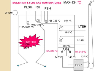
- 35. BOILER AIR & FLUE GAS TEMPERATURES PLSH RH MAX-134 ºC FSH DRUM 758-726 ºC 720 ºC 1020-793 ºC 1135-1020 ºC LTSH 461 ºC ECO 11001250 355 ºC SA-318 ºC APH A B 147 ºC PA-313 ºC 143 ºC 137 ºC ESP
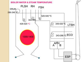
- 36. BOILER WATER & STEAM TEMPERATURE PLSH RH DRUM FSH 286-349 ºC 520-540 ºC 344-540 426-520 ºC 1300-1400 349-426 ºC LTSH 243-286 ºC ECO APH A B ESP
- 37. M.S H. R. H C.R.H 500MW BOILER BCW Pump FROM F.R.S BOTTOM RNG HDR WW PANELS & 1ST PASS W.W. 1ST PASS W.W O/L HDRS ROOF I/L HEADER 2ND 2nd PASS LOWER C-HDRS PASS UPPER C-HDR LTSH I/L HEADER LTSH & O/L HEADER D.P.I/L HEADER D.P.O/L HEADER FINAL S.H. R.H.HEADER 2ND ECONOMISER PASS ROOF O/L HDR(REAR