Nuisance Tripping - True RMS Measurements
•
0 likes•1,183 views

The document discusses nuisance tripping of circuit breakers caused by inrush currents from electronic equipment and under-measurement of distorted load currents. It recommends using true RMS measurement instruments, which account for harmonic distortions, to properly measure load currents. The document presents a case study where nuisance tripping of circuit breakers from computer equipment was resolved by changing to type D circuit breakers, which are less sensitive to high inrush currents. It also explains how under-measuring distorted currents can lead to overheating of wiring and overloads on equipment rated based on heat dissipation from RMS current values.
Report
Share


Nuisance Tripping - True RMS Measurements
- 1. European Copper Institute APPLICATION NOTE NUISANCE TRIPPING (TRUE RMS MEASUREMENTS) David Chapman, European Copper Institute October 2011 ECI Publication No Cu0110 Available from www.leonardo-energy.org/drupal/node/3942
- 2. Publication No Cu0110 Issue Date: October 2011 Page i Document Issue Control Sheet Document Title: Application Note – Nuisance Tripping (formerly called ‘True RMS’) Publication No: Cu0110 Issue: 02 Release: October 2011 Author(s): David Chapman Reviewer(s): / Document History Issue Date Purpose 1 March 2001 Part of the Power Quality Application Guide, published under the name ‘True RMS – the only true measurement’ 2 October 2011 Reworked by the author for adoption in the Good Practice Guide 3 Disclaimer While this publication has been prepared with care, European Copper Institute and other contributors provide no warranty with regards to the content and shall not be liable for any direct, incidental or consequential damages that may result from the use of the information or the data contained. Copyright© European Copper Institute. Reproduction is authorised providing the material is unabridged and the source is acknowledged.
- 3. Publication No Cu0110 Issue Date: October 2011 Page ii CONTENTS Summary ........................................................................................................................................................ 1 Nuisance tripping............................................................................................................................................ 2 Inrush Currents.......................................................................................................................................................2 Case study ................................................................................................................................................2 True RMS – The Only True Measurement ..............................................................................................................5 What is RMS? ...........................................................................................................................................6 The consequences of under measurement..............................................................................................8 Conclusion ...................................................................................................................................................... 9
- 4. Publication No Cu0110 Issue Date: October 2011 Page 1 SUMMARY Nuisance tripping of circuit breakers is a common problem in many commercial and industrial installations. This Application Note explains the need to use ‘True RMS’ measurement instruments when troubleshooting and analyzing the performance of a power system. Nuisance tripping is often caused by the load current being distorted by the presence of harmonic currents drawn by non-linear loads. Harmonic currents distort the current waveform and increase the load current required to deliver energy to the load. Many measurement instruments, even quite modern ones, use an averaging measurement technique that does not measure harmonic currents correctly. ‘True RMS’ meters take the complete distorted waveform into account. If averaging meters are used to measure distorted current, the readings may be as much as 40% too low. Circuit breakers and cable sizes may be underrated as a result.
- 5. Publication No Cu0110 Issue Date: October 2011 Page 2 NUISANCE TRIPPING Many commercial and industrial installations suffer from persistent so-called ‘nuisance tripping’ of circuit breakers. The term refers to the apparently random and inexplicable nature of these events which, although there is no apparent fault, can cause significant disruption and financial loss. Of course, there is always a reason for the nuisance tripping of a breaker and there are two common causes. The first possible cause is the inrush currents that occur when some loads, particularly personal computers and other electronic devices, are switched on. The second possible cause is that the true RMS current flowing in the circuit has been under- measured – in other words, the true current really is too high and the trips are valid. INRUSH CURRENTS Modern electronic equipment, such as personal computers, monitors, television sets and office equipment, uses a type of power supply that converts mains electricity to the low voltage direct current without a low frequency transformer. This type of supply is known as a switched mode power supply (SMPS) and works by rectifying mains current directly and storing the direct voltage on a large capacitor which charges to the peak of the supply voltage. Conversion circuits draw current from the capacitor and generate the required low voltage, usually via a high frequency transformer to provide galvanic isolation. SMPS is very cheap, but it causes problems in installations because it produces large harmonic currents and draws very large inrush currents to initially charge the storage capacitor. Many PCs are never actually ‘turned off’ – in the sense of being electrically isolated from the supply - but remain powered in standby mode and can be ‘woken up’ by user input, modem activity, or by a network message. On wake up, they draw a starting current very similar to that drawn when starting from cold. CASE STUDY In a small computer room at the University of Sheffield (UK) circuit breakers were being tripped apparently at random but particularly during the night. Groups of 16 computers were connected to standard final circuits, each protected by a 32 A miniature circuit breaker. A preliminary investigation revealed nothing – the installation was apparently correctly installed and functioning correctly. As the problem persisted, further tests revealed that the trips occurred at the start of the nightly maintenance procedure as the computers turned back on and it was realized that the inrush current was responsible. Further inspection revealed that the MCBs were type B devices so they were replaced with type D devices of the same rating – this will be discussed in detail later. Although this change resolved the problem, a measurement exercise was undertaken to verify the conclusion. A logic controlled switch was interposed at the load side of one of the breakers together with a transient recorder to measure the applied voltage and current. The switch was capable of applying the supply voltage at a defined point on the voltage waveform. A number of startup cycles were conducted and the inrush currents recorded. Figure 1 shows the inrush current for a typical personal computer and (CRT) monitor set with the supply voltage applied close to the positive voltage peak. At 155 A, this was the worst case – i.e. the maximum – inrush current recorded during the testing for this configuration. The voltage waveform is shown only for clarity but it is interesting to note the resulting distortion of the supply waveform, especially on the first half cycle. The steady state current consumption was 0.75 A. The current and time resolutions of the measurements are 0.28 A and 0.8 mS respectively.
- 6. Publication No Cu0110 Issue Date: October 2011 Page 3 Figure 1 – Inrush current for one computer/monitor pairs fed by a normal final circuit. Figure 2 shows the result with 16 computer/monitor pairs connected, the worst case peak current being 583 A. The current and time resolutions of the measurements in this case are 1.12 A and 0.8 mS respectively. Figure 2 – Inrush current for 16 computer/monitor pairs fed by a normal final circuit.
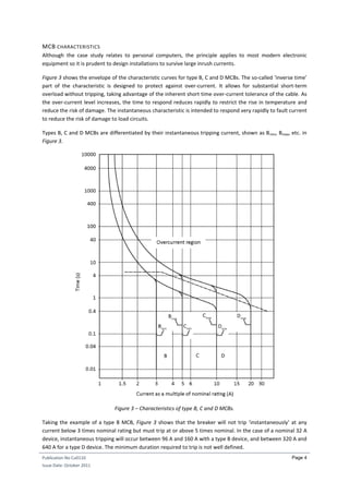
- 7. Publication No Cu0110 Issue Date: October 2011 Page 4 MCB CHARACTERISTICS Although the case study relates to personal computers, the principle applies to most modern electronic equipment so it is prudent to design installations to survive large inrush currents. Figure 3 shows the envelope of the characteristic curves for type B, C and D MCBs. The so-called ‘inverse time’ part of the characteristic is designed to protect against over-current. It allows for substantial short-term overload without tripping, taking advantage of the inherent short time over-current tolerance of the cable. As the over-current level increases, the time to respond reduces rapidly to restrict the rise in temperature and reduce the risk of damage. The instantaneous characteristic is intended to respond very rapidly to fault current to reduce the risk of damage to load circuits. Types B, C and D MCBs are differentiated by their instantaneous tripping current, shown as Bmin, Bmax, etc. in Figure 3. Figure 3 – Characteristics of type B, C and D MCBs. Taking the example of a type B MCB, Figure 3 shows that the breaker will not trip ‘instantaneously’ at any current below 3 times nominal rating but must trip at or above 5 times nominal. In the case of a nominal 32 A device, instantaneous tripping will occur between 96 A and 160 A with a type B device, and between 320 A and 640 A for a type D device. The minimum duration required to trip is not well defined.
- 8. Publication No Cu0110 Issue Date: October 2011 Page 5 From the case study results, it is clear that a type B MCB could trip due to the inrush current from one computer/monitor pair while selecting a type D device would provide a degree of protection against nuisance tripping. Changing the MCB type means that the potential fault current is increased so the loop impedance of the final circuit should be carefully checked to ensure compliance with the applicable regulations. In cases where the inrush is too high for any available breaker, problem loads should be distributed among more final circuits. TRUE RMS – THE ONLY TRUE MEASUREMENT Why do under-measurements occur frequently in modern installations even though digital test instruments are so accurate and reliable? The answer is that many instruments are not suitable for measuring distorted currents - and most currents these days are distorted. Since currents are being under-measured, the real current is much closer to the nominal breaker current than believed, leading to genuine trips that are misinterpreted as nuisance trips. This distortion is due to harmonic currents drawn by non-linear loads, especially electronic equipment such as personal computers, electronically ballasted fluorescent lamps and variable speed drives. Figure 6 shows the typical current waveform drawn by a personal computer. Obviously, this is not a sine wave and all the usual sine wave measurement tools and calculation techniques no longer work. This means that, when troubleshooting or analyzing the performance of a power system, it is essential to use the correct tools for the job – tools that can deal with non-sinusoidal currents and voltages. Figure 4 shows two clamp-meters on the same branch circuit. Both the instruments are functioning correctly and both are calibrated to the manufacturer’s specification. The key difference is in the way the instruments measure. Figure 4 - One current, two readings. Which do you trust? The circuit feeds a non-linear load with distorted current. The True RMS clamp (left) reads correctly but the average responding clamp (right) reads low by 32%.
- 9. Publication No Cu0110 Issue Date: October 2011 Page 6 The left-hand meter is a true RMS instrument and the right-hand one is an averaging reading RMS calibrated instrument. Appreciating the difference requires an understanding of what RMS really means. WHAT IS RMS? The ‘Root Mean Square’ magnitude of an alternating current is the value of equivalent direct current that would produce the same amount of heat in a fixed resistive load. The amount of heat produced in a resistor by an alternating current is proportional to the square of the current averaged over a full cycle of the waveform. In other words, the heat produced is proportional to the mean of the square of the current, so the equivalent current value is proportional to the root of the mean of the square or RMS. (The polarity is irrelevant since the square is always positive.) For a perfect sine wave, such as that seen in Figure 5, the RMS value is 0.707 times the peak value (or the peak value is 2, or 1.414, times the RMS value). In other words the peak value of 1 amp RMS pure sine wave current will be 1.414 amps. If the magnitude of the waveform is simply averaged (inverting the negative half cycle), the mean value is 0.636 times the peak, or 0.9 times the RMS value. There are two important ratios shown in Figure 5: And Figure 5 - A pure sine wave. When measuring a pure sine wave – but only for a pure sine wave – it is quite correct to make a simple measurement of the mean value (0.636 x peak) and multiply the result by the form factor 1.111 (making 0.707 times peak) and call it the RMS value. This is the approach taken in all analogue meters (where the averaging is performed by the inertia and damping of the coil movement) and in all older and many currently available digital multimeters. This technique is described as ‘mean reading, RMS calibrated’ measurement. The problem is that the technique only works for pure sine waves and pure sine waves do not exist in the real world of an electrical installation. The waveform in Figure 6 is typical of the current waveform drawn by a
- 10. Publication No Cu0110 Issue Date: October 2011 Page 7 personal computer. The true RMS value is still 1 amp, but the peak value is much higher, at 2.6 amps, and the average value is much lower, at 0.55 amps. Figure 6 - Typical waveform of current drawn by a personal computer. If this waveform is measured with a mean reading, RMS calibrated meter it would read 0.61 amps, rather than the true value of 1 amp, nearly 40% too low. Figure 7 below gives some examples of the way the two different types of meters respond to different wave shapes. Figure 7 – Response of mean reading and true RMS meters to various waveshapes. A true RMS meter works by taking the square of the instantaneous value of the input current, averaging over time and then displaying the square root of this average. Perfectly implemented, this is absolutely accurate whatever the waveform. Implementation is, of course, never perfect and there are two limiting factors to be taken into account: frequency response and crest factor. For power systems work it is usually sufficient to measure up to the 50 th harmonic, i.e. up to a frequency of about 2500 Hz. The crest factor, the ratio between the peak value and the RMS value, is important; a higher crest factor requires a meter with a greater dynamic range and therefore higher precision in the conversion circuitry. A crest factor capability of at least three is required for accurate measurement in power installations. It is worth noting that, despite giving different readings when used to measure distorted waveforms, meters of both types would agree if used to measure a perfect sine wave. This is the condition under which they are calibrated, so each meter could be certified as calibrated – but only for use on sine waves. True RMS meters have been available for at least the past 30 years, but they used to be specialized and expensive instruments. Advances in electronics have now resulted in true RMS measurement capability being
- 11. Publication No Cu0110 Issue Date: October 2011 Page 8 built into many handheld multimeters. Unfortunately, this feature is generally found only towards the top end of most manufacturers’ ranges, but they are still cheap enough to buy as ordinary instruments for everyone and every day. THE CONSEQUENCES OF UNDER MEASUREMENT The limiting rating for most electrical circuit elements is determined by the amount of heat that can be dissipated so that the element or component does not overheat. Cable ratings, for example, are given for particular installation conditions (which determine how fast heat can escape) and a maximum working temperature. Since harmonic polluted currents have a higher RMS value than that measured by an averaging meter, cables may have been under-rated and will run hotter than expected; the result is degradation of the insulation, premature failure and the risk of fire. Busbars are sized by calculating the rate of heat loss from the bars by convection and radiation and the rate of heat gain due to resistive losses. The temperature at which these rates are equal is the working temperature of the busbar, and it is designed so that the working temperature is low enough so that premature ageing of insulation and support materials does not result. As with cables, errors measuring the true RMS value will lead to higher running temperatures. Since busbars are usually physically large, skin effect is more apparent than for smaller conductors, leading to a further increase in temperature. Other electrical power system components such as fuses and the thermal elements of circuit breakers are rated in RMS current because their characteristics are related to heat dissipation. This is the root cause of nuisance tripping – the current is higher than expected so the circuit breaker is operating in an area where prolonged use will lead to tripping. The response of a breaker in this region is temperature sensitive and may appear to be unpredictable. As with any supply interruption, the cost of failure due to nuisance tripping can be high, causing loss of data in computer systems, disruption of process control systems, etc.
- 12. Publication No Cu0110 Issue Date: October 2011 Page 9 CONCLUSION This paper has described two common causes of nuisance tripping. In each case there are some simple preventive steps. Avoiding tripping due to inrush currents simply requires selection of the correct type of breaker and sensible distribution of loads among circuits. Under-measurement is easily avoided by ensuring that true RMS meters are used routinely. Knowledge of the real current in a circuit allows corrective action to be taken, for example, redistributing loads across final circuits.