This document provides an overview of radiation health and safety concepts for dental assistants. It discusses the discovery of x-rays, atomic structure, how dental x-rays are produced, and the components and operation of dental x-ray machines. The key points are that radiation has the potential to damage living tissues, dental assistants must understand radiation fundamentals to minimize patient and operator exposure, and dental x-rays are produced via the acceleration of electrons in an x-ray tube.
The xeroradiographic plate consists of the following layers:
1. An aluminum substrate that provides a smooth surface for the photoconductor layer.
2. An interface layer of aluminum oxide between the selenium photoconductor and aluminum substrate to prevent charge exchange.
3. A selenium photoconductor layer that becomes electrically conductive upon exposure to x-rays, forming a latent electrostatic image.
4. A protective coating over the selenium layer to prevent degradation and improve shelf life.
The document describes the composition and uses of intraoral and extraoral films and intensifying screens used in dental radiography. It discusses the components of intraoral and extraoral films, including the plastic base, double emulsion containing silver halide crystals, and protective layers. It also describes the composition and function of intensifying screens containing rare earth phosphor crystals that emit light when exposed to x-rays. The document provides details on different film types, speeds, sizes and storage as well as cassette, barrier packets and processing.
This document discusses collimation and filtration in dental x-rays. It explains that collimators are used to restrict the size of the x-ray beam in order to minimize radiation exposure and scattered radiation. There are different types of collimators including diaphragm, round, rectangular, and slit collimators. Filtration is also discussed, which involves removing low-energy photons from the beam to reduce unnecessary radiation exposure while maintaining diagnostic image quality. Common filtration materials mentioned are aluminum, copper, tin, and lead. The effects of proper collimation and filtration are to harden the beam and reduce radiation dose to patients.
There are three key components of an image receptor for conventional radiography: film to record the image, intensifying screens to expose the film by converting x-rays to light, and a cassette to protect the screens and film. Intensifying screens, usually made of phosphors like calcium tungstate or rare earth elements, absorb around 30% of x-rays and emit visible light, allowing lower radiation doses while slightly blurring the image. Most cassettes have a pair of screens sandwiching double emulsion film to contribute evenly to the latent image, which is less than 1% from direct x-ray exposure.
Radiographic intensifying screens are crucial components in radiography that enhance image quality and reduce patient radiation exposure. They consist of three layers - a phosphor layer that converts x-ray energy into visible light, a reflective layer that directs this light towards the film, and a supportive base layer. Together, these screens work with radiographic films to improve diagnostic images while minimizing the needed radiation dose. Regular maintenance of intensifying screens is important to ensure consistent, high-quality images over time.
This document discusses the components and properties of x-ray film. It describes the base, emulsion layer, and other parts of the film. The base provides structural support and is made of polyester or polyethylene terephthalate. The emulsion layer contains silver halide crystals suspended in a gelatin matrix. It responds to x-rays by forming latent images. The document also discusses film speed, types of film for different uses, and the difference between single and double coated films.
A dental x-ray machine consists of a tubehead, support arms, and control panel. The tubehead contains an x-ray tube with a cathode and anode, as well as transformers that convert electrical current. The control panel regulates voltage and current to the x-ray tube. Dental x-rays are collimated and filtered to shape and soften the beam, reducing radiation exposure for patients.
This document provides information on intensifying screens and radiographic grids. It discusses the history, construction, and functions of intensifying screens, including the types of phosphors used. It also covers screen speed, detail, and care. For radiographic grids, it outlines the history and development of grids as well as grid design, patterns, specifications and factors such as ratio and frequency. Research studies evaluating different screen-film combinations and their effects on image quality and radiation dose are also summarized.
Modern medical imaging has been digitized using various technologies which are described here in this presentation.Presented in Department of radiology, ,B.Sc Medical Imaging technology,Institute of Medicine, Nepal.
This document discusses dental radiography and x-rays. It defines key terms like radiograph and radiology. It describes the components of a dental x-ray unit and different types of radiographs like bitewings and panoramic x-rays. It discusses techniques like paralleling, bisecting angle technique and SLOB technique. It also covers topics like indications for radiographs, radiation safety, and advantages and disadvantages of digital radiography compared to conventional film.
The document discusses different types of radiography technologies, including computed radiography (CR), direct digital radiography (DR), and the components and layers of imaging plates (IPs) used in CR. It also covers image processing techniques for CR/DR such as histogram generation, exposure compensation, and potential artifacts that can occur during acquisition, post-acquisition or display.
This document discusses image receptors used in dental radiography. It defines image receptors, provides a brief history, and classifies receptors as analog film or digital sensors. It describes common intra-oral and extra-oral radiographs and films used, and compares analog film speeds and packaging types. Digital receptors like CCD, CMOS, and PSP sensors are also outlined. The document reviews pathogens that can survive on receptors and strategies to reduce cross-contamination risk. Overall, the document provides a comprehensive overview of analog and digital dental image receptors.
"A latent image is an invisible image that is created during the imaging process in medical radiology."
Importance: "Understanding latent images is crucial in medical radiology as it forms the foundation for diagnostic imaging techniques."
State the objectives of this presentation: "Today, we will explore the formation of latent images, their role in various imaging modalities, and their significance in the field of radiology."
Latent Image formation & Dark room Chemistry.pptxssuser71d7b1
This document discusses latent image formation on dental radiographic film and the darkroom chemistry involved in processing the film. It begins by explaining how x-ray photons interact with silver halide crystals in the film emulsion to form a latent image. It then describes the key components and functions of the darkroom, including safe lighting, temperature and humidity control. Finally, it provides details on manual and automatic film processing, the chemical compositions and purposes of developer and fixer solutions, and some additional darkroom techniques.
This document provides information on various types of image receptors used in dental radiography. It discusses the history of x-ray film and describes the components of intraoral and extraoral films. It also covers intensifying screens, digital receptors like CCD, CMOS, and flat panel detectors, and photo stimulable phosphor plates. The document details the composition of films and screens and factors affecting film speed, contrast, and detail. It compares the advantages and disadvantages of screen-film systems and digital receptors.
Dental radiography involves taking images of the teeth, bones, and soft tissues in the mouth to aid in diagnosis and treatment planning. There are several types of dental radiography procedures, including intraoral radiographs like bitewings and periapicals, as well as panoramic and cephalometric images. Radiographs are useful for detecting issues like dental caries, abnormalities, and monitoring treatment. Proper radiation safety protocols must be followed when performing dental radiography to minimize risk to patients and staff.
This document discusses the effects of kVp and mAs on various properties of x-ray images. It explains that kVp determines the highest x-ray energy and quality, while mAs determines the quantity of photons and exposure time. Higher kVp and mAs increase spatial resolution, contrast, and signal-to-noise ratio, but also increase radiation dose. The document covers these parameters for screen-film radiography as well as computed tomography, and how they impact visible properties like image noise, contrast, and resolution.
This document discusses characteristics of x-ray images and artifacts. It defines key terms like image, real image, noise, contrast, sharpness and resolution. Noise appears due to factors like scattered radiation and can be reduced using techniques like high mAs and low kVp. Contrast is the difference in density between structures. Sharpness is related to density gradients at boundaries between areas. Resolution refers to the ability to show small, closely spaced structures separately. Artifacts are unwanted signs produced by technical errors in exposure, processing or handling that interfere with image quality. Understanding these characteristics and sources of artifacts is important for producing high quality medical images.
This document discusses radiographic grids, which are devices placed between the patient and image receptor to absorb scatter radiation and improve image quality. It defines grids and their construction using lead strips and spacers. It describes different grid patterns, ratios, frequencies, and types. It also covers topics like primary transmission, grid conversion factor, contrast improvement, and causes of grid cut-off like decentering errors. The key purpose of grids is to absorb scattered radiation and improve radiographic contrast for diagnostic purposes, while minimizing additional patient dose. Grid selection involves balancing image quality with keeping patient exposure as low as reasonably achievable.
brief description about CONTENTS Introduction Principles of panoramic imaging Image layer Panoramic machines Panoramic film Patient positioning Interpreting the panoramic imaging INDICATION Advantages Disadvantages Conclusion References
3. INTRODUCTION • Panoramic imaging also called pantomography is a technique for producing a single tomographic image of facial structures that includes both the maxillary and mandibular dental arches and their supporting structures . • This is a curvilinear variant of conventional tomography.
4. PRINCIPLES OF PANORAMIC IMAGE FORMATION • Patero and Numata - describe the principles of panoramic radiography • based on the principle of reciprocal movement of x-ray source and an image receptor around a central point or plane called the image layer, in which the OBJECT of image is located. • OBJECT in front or behind this image are not clearly captured because of their movement relative to the centre of rotation of the receptor and the x-ray source.
5. The film and x-ray tubehead move around the patient in opposite directions in panoramic radiography
6. ROTATION CENTER The pivotal point or axis around which the cassette carrier and tube head rotate is termed rotation center Three basic rotation center used in panoramic radiography Double centre rotation Triple centre rotation moving centre rotation The location and number of rotational centers INFLUENCE size and shape of focal trough
7. IMAGE LAYER • Also known as focal trough • It is a three dimensional curved zone where the structures lying within this layer are reasonably well defined on final panoramic image. • The structures seen on a panoramic image are primarily those located within image layer. • OBJECTSoutside the image layer are blurred magnified are reduced in size. Even distorted to the extent of not being recognizable. • This shape of image layer varies with the brand of equipment used.
8. FOCAL TROUGH
9. FACTORS AFFECTING SIZE OF IMAGE LAYER: Arc path Velocity of receptor and X-ray tube head Alignment of x-ray beam Collimator width The location of image layer change with extensive machine used so recalibration may be necessary if consistently suboptimal images are produced. As a position of object is moved within the image layer size and shape of image layer change.
10. PANORAMIC UNIT
11. A, Orthophos XG Plus extraoral x-ray machine. B, Orthoralix 8500 extraoral x-ray machine. C, Example of a digital panoramic system
12. PARTS OF PANORAMIC UNITS a. x-ray tube head b. head positioner: chin rest notched bite block forehead rest lateral head support c. exposure controls
13. X-RAY TUBE HEAD: • Similar to intraoral x-ray tube head • Each has a filament to produce electrons and a target to produce x-rays • Collimator is a lead plate with narrow vertical slit • Narrow x-ray beam emerges from collimator minimize patient exposure to radiation
1
Dental x-rays help visualize parts of the teeth and jaws that cannot be seen normally. There are different types of intra-oral and extra-oral x-rays used for various purposes like detecting decay, evaluating bone quality, and examining the jaw and salivary glands. Modern digital x-ray systems offer advantages over conventional film x-rays like reduced radiation exposure and ability to enhance images electronically.
Panoramic radiography, also known as dental panoramic tomography (DPT), produces a single image of the facial structures including both dental arches. It utilizes a technique called tomography, which produces radiographs of a thin section or slice of the patient. In panoramic radiography, the x-ray tube and film rotate synchronously around the patient's head within a focal trough, producing multiple images that are merged into a single panoramic view. This provides visualization of teeth and jaws while minimizing radiation exposure compared to full mouth x-rays. Exact patient positioning is important for obtaining diagnostic quality images.
A radiographic grid is a device placed between the patient and x-ray film to absorb scattered radiation and improve image contrast. It consists of alternating strips of radiopaque lead and radiolucent material. The grid allows primary x-rays to pass through while blocking scattered x-rays, reducing image blurring. Higher grid ratios and frequencies block more scatter but can also cut off parts of the primary beam if not positioned correctly. Grid selection depends on patient thickness, desired technique, and exam type. While improving contrast, grids also increase patient radiation dose.
Radiation comes in two forms - particulate and electromagnetic. Dental radiographs use x-rays to produce images of teeth and surrounding structures. There are three main types of intraoral dental x-rays: periapical for the tooth apex, bitewing between teeth, and occlusal for larger areas. Dental films contain a silver halide emulsion layered between a transparent base and protective coating to capture x-ray images.
CBCT provides high resolution 3D imaging of the maxillofacial region with lower radiation dose compared to medical CT. It has become an important tool in dentistry since its introduction in the late 1990s. CBCT works by taking X-ray images of the head from different angles and using complex algorithms to reconstruct 3D volumetric images. While it offers advantages over 2D imaging, CBCT is also subject to various artifacts from beam hardening, metal objects, and patient movement. Proper use and understanding of these limitations is important for accurate interpretation of CBCT scans.
Cassettes contain intensifying screens and hold film during x-ray examinations. Intensifying screens convert a small percentage of x-ray photons that pass through the patient into visible light photons, which expose the film. This process increases the number of photons available to expose the film while significantly reducing the radiation dose to the patient compared to directly exposing the film. Modern rare earth screens are most efficient at this conversion but provide less image detail than earlier calcium tungstate screens or direct exposure of film.
An X-ray tube is a critical medical and scientific instrument that plays a fundamental role in generating X-rays for various applications. X-ray tubes are widely used in the field of medicine for diagnostic imaging, as well as in industrial and scientific settings for materials analysis and research.
3.X-RAY PROPERTIES,PRODUCTION AND INTERACTION WITH MATTER.pptx by Ravindra Ku...Ravindra Kumar
On Friday 8th Nov 1895 German physicist Sir Wilhelm Conrad Roentgen discovered X-rays.
X rays belong to a group of radiations called electro magnetic radiation.
Electro magnetic radiation is transport of energy through space as combination of electric and magnetic field.
Born: 27 March 1845, Lennep (Now Germany)Died: 10 February 1923, Munich, GermanyAffiliation at the time of the award: Munich University, Munich, GermanyPrize motivation: "in recognition of the extraordinary services he has rendered by the discovery of the remarkable rays subsequently named after him."Röntgen married Anna Bertha Ludwig of Zürich, whom he had met in the café run by her father.She was a niece of the poet Otto Ludwig. They married in 1872 in Apeldoorn, The Netherlands.They had no children, but in 1887, they adopted Josephine Bertha Ludwig, who was then aged 6 and the daughter of Anna Bertha’s only brother. Four years after his wife, Röntgen died in Munich on February 10, 1923, from carcinoma of the intestine.
Roentgen was awarded the first Nobel Prize in physics in 1901 for his discovery. When asked what his thoughts were at the moment of discovery, he replied, true to form, "I didn't think, I investigated.“Today, Roentgen is widely recognized as a brilliant experimentalist who never sought honors or financial profits for his research. He rejected a title that would have given him entry into the German nobility, and donated his Nobel Prize money to his university. While he accepted the honorary degree of doctor of medicine offered to him by his own university, he never took out any patents on X-rays, to ensure that the world could freely benefit from his work. His altruism came at considerable personal cost: at the time of his death in 1923, Roentgen was nearly bankrupt from the inflation following World War 1.
X-Rays have so much energy and such a short wavelength that they can go right through us.
However, they cannot get through bone as easily as they can get through muscle.
X-rays are generated by electronic transitions involving highly energetic inner atomic electrons.
Properties of x-rays:
X-ray are invisible.
They have no mass, weight, or charge.
X-rays are electrically neutral.
It behaves as waves as well as particles.
It travels at the speed of light with 3*108m/s.
X-rays are produced when fast-moving electrons strike on a metal object.
The kinetic energy of the electron is transformed into electromagnetic energy.
The function of the X-ray machine is to provide a sufficient intensity of electron flow from the cathode to the anode in a controlled manner.
X-RAYS ARE PRODUCED BY TWO PROCESSES
1. BREMSSTRAHLUNG RADIATION: Also called brems, white or general radiation.
Derived from two German words Brems –brake & strahl-ray.
Called braking radiation, the radiation is produced by braking or decelerating high-speed electrons.
2. Characteristic x-rays: result when the interaction is sufficiently violent to ionize the target atom.
The document provides an overview of radiation physics, beginning with the composition of matter and basic atomic structure. It describes the Bohr-Rutherford model of the atom and the development of the quantum mechanical model. Key concepts covered include atomic number, mass number, ionization, electrostatic and centrifugal forces, electron binding energy, and the nature of radiation.
The document then focuses on the history and properties of x-rays, the components and functioning of an x-ray machine, including the x-ray tube, cathode, anode, target, transformers, and power supply. Factors that control the x-ray beam such as exposure time, current and voltage are also summarized.
This document discusses atomic theory and electromagnetic radiation, including x-rays. It provides an overview of the atomic structure, including protons, neutrons, and electrons. It describes the electromagnetic spectrum and different types of ionizing radiation. X-rays are used in diagnostic imaging like radiography, fluoroscopy, mammography, and CT scans. Proper protection methods are needed to reduce radiation exposure for patients, staff, and the public.
it describes about electron beam characteristics and applications and it outlines the following topics introduction, E-beam processing, E-beam equipment and applications.
The Indian Dental Academy is the Leader in continuing dental education , training dentists in all aspects of dentistry and
offering a wide range of dental certified courses in different formats.
radiation physics is important to know for dental student to be able to utlize xray and to know the benefita and overcome the hazards of radiation. in this lecture history of discovery of xray and properties of xrays and properties of elecromagnetic waves. mechanism of xay production and parts of ddental xray machine morreover the factors affecting image quality is also discussed in details . diagrams and images are included for verification
X-rays are a type of electromagnetic radiation that can pass through objects like skin and be used to see inside the body. They are produced when high energy electrons interact with matter. X-rays are used in medical imaging to diagnose bone injuries and examine the inside of the body. They can pass through soft tissue like skin and lungs but are absorbed by dense tissues like bones, causing bones to appear white on X-ray images while lungs appear black. Exposure to X-rays can be harmful and cause health issues like burns, cancer, and birth defects.
Radiological anatomy uses various imaging techniques like X-rays, CT, MRI, ultrasound and nuclear medicine to visualize and study normal human anatomy. X-rays were discovered in 1895 and work by penetrating tissues at different levels based on density. Dense tissues like bone appear white on X-rays while less dense tissues are darker. Radiological anatomy allows inspection of internal structures and functions in a non-invasive manner compared to gross anatomy. Standard views and different types of radiographs are used to study different anatomical regions.
CT uses radiation to produce 3D images of the body. It was originally used for oncology and cardiology but is now used more broadly. During a CT scan, x-rays pass through the body and are measured to construct images. There are several types of interactions between x-rays and matter, such as the photoelectric effect where an x-ray ejects an electron from an atom. X-rays are produced in an x-ray tube, where a stream of electrons accelerated toward a metal target produce x-rays through bremsstrahlung radiation. The x-ray tube is a key component of devices used for medical imaging and radiation therapy.
- There are two main systems for measuring radiation - the conventional US system and the International System of Units (SI).
- Radioactivity is measured in curies (Ci) in the US system and becquerels (Bq) in the SI system. 1 Ci equals 37 billion Bq.
- Exposure rate is measured in roentgens (R) per hour in the US system. The SI unit is the coulomb per kilogram (C/kg).
- Absorbed dose is measured in rads in the US system and grays (Gy) in the SI system. 1 Gy is equal to 100 rads.
The document discusses particle accelerators and nuclear physics. It provides definitions of particle accelerators and describes their basic working principle of using electromagnetic fields to accelerate charged particles. It discusses different types of particle accelerators like linear accelerators, cyclotrons, synchrotrons and their components and working. The largest particle accelerators in the world, like the LHC and RHIC, are mentioned. Applications of particle accelerators discussed include uses in medicine, industry, DNA research and treating cancer.
A synchrotron is a large machine that uses powerful magnets and radio waves to accelerate electrons to near light speed. As the electrons are deflected by magnetic fields, they emit extremely bright light across the electromagnetic spectrum. This synchrotron light is channeled to experimental stations where it is used for research in fields like medicine, materials science, and biology due to its high intensity and tunable wavelengths.
A Review- Basic of Laser and Its Role in Periodontics: Part Iiosrjce
IOSR Journal of Dental and Medical Sciences is one of the speciality Journal in Dental Science and Medical Science published by International Organization of Scientific Research (IOSR). The Journal publishes papers of the highest scientific merit and widest possible scope work in all areas related to medical and dental science. The Journal welcome review articles, leading medical and clinical research articles, technical notes, case reports and others.
The document discusses X-rays, including their history, generation, applications, and challenges. It provides details on how Wilhelm Roentgen accidentally discovered X-rays in 1895 while experimenting with electron beams. X-rays are generated when high-energy electrons strike an anode target, releasing 1% of their kinetic energy as X-rays. X-rays are used widely in medicine for diagnostic imaging like bone structure imaging, as well as in security screening, scientific research, and archaeology. However, diagnostic X-ray radiation poses cancer and tumor risks if overexposed.
- Historically, diagnosis involved observing patients outwardly for symptoms or surgically opening the body, which risked trauma and infection. Modern techniques use externally placed devices like X-rays, ultrasound and MRI to non-invasively obtain internal information.
- X-rays are produced when high-speed electrons bombard a metal target, generating electromagnetic Bremsstrahlung radiation in the X-ray region. The electron's kinetic energy determines the minimum X-ray wavelength.
- A modern X-ray tube contains a heated cathode that emits electrons, which are accelerated towards an anode. The tube current controls intensity, while voltage controls penetration ("hardness") of the X-ray beam. An aluminum
Ultrasound Transducer Constriction And It’s Physics.pptxDr. Dheeraj Kumar
Definition of Ultrasound Transducer: An ultrasound transducer is a critical device used in medical imaging to both emit and receive ultrasound waves for diagnostic purposes.
Importance of Understanding Transducers: Mastering the principles of transducer physics and construction is essential for radiology students, as it forms the foundation for proficient ultrasound operation and interpretation.
Presentation Structure: This presentation will delve into the physics behind ultrasound transducers, the materials used in their construction, and the functions of their key components.
This document contains summaries of chapters from the book "Computer Networks" by Andrew Tanenbaum and David Wetherall. It discusses topics related to computer networks and the application layer, including the Domain Name System (DNS), electronic mail, the World Wide Web, streaming audio and video. For each topic, it provides brief explanations and examples to illustrate key concepts from the text.
The document discusses Transcutaneous Electrical Nerve Stimulation (TENS). TENS uses electrical impulses from a battery-powered pulse generator attached to electrode-tipped wires placed on the skin over painful areas. This electrical stimulation blocks pain signals from reaching the brain through the Gate Control Theory and by stimulating the release of natural pain-blocking endorphins. TENS machines have adjustable settings to control intensity, pulse duration and frequency in order to effectively relieve pain through electrical stimulation of nerve pathways.
The document discusses Transcutaneous Electrical Nerve Stimulation (TENS). TENS uses electrical impulses from a battery-powered device called a TENS unit to relieve pain. Electrodes attached to the skin deliver mild electric pulses that interfere with pain signals traveling to the brain. The TENS unit can be adjusted to control pulse intensity, duration and frequency. TENS is a non-invasive way to reduce pain without side effects of medications.
The review meeting covered responsibilities in the hostel since February 2016 along with the hostel superintendent. Key responsibilities included facility creation and maintenance, handling disciplinary issues, sanctioning leaves, collecting fees, and holding meetings. Facilities created included Wi-Fi, a system with printer, and a television. Two major disciplinary issues involved possession of mobile phones and using laptops without permission. Fees were collected from students in different years. Hostel day was held in March 2016 and April 2017 with chief guests from local hospitals and the college. Areas for improvement included water facilities and managing electronic gadget usage.
The document discusses electromagnetic compatibility (EMC) design considerations for circuits and printed circuit boards (PCBs). It covers topics like noise from relays and switches, nonlinearities in circuits, cross talk control, component selection and mounting, PCB trace impedance, routing, power distribution, decoupling, zoning, grounding, vias and terminations. It provides details on controlled impedance PCB trace design, factors that determine trace impedance, guidelines for board-level decoupling including capacitor placement based on plane spacing.
The review meeting covered responsibilities in the hostel since February 2016 along with the hostel superintendent. Key responsibilities included facility creation and maintenance, handling disciplinary issues, sanctioning leaves, collecting fees, and holding meetings. Facilities created included Wi-Fi, a system with printer, and a television. Two major disciplinary issues addressed were possession of mobile phones and using laptops without permission. Fees collected were detailed by academic year. Hostel day was held in March 2016 and April 2017 with notable chief guests. Areas for improvement included water facilities and regulating electronic gadget usage.
The document proposes a real-time smart epilepsy detection and alert system using IoT. It aims to help epilepsy patients avoid unpredictable violent seizures caused by sudden falling. The proposed system uses a heart rate sensor and MEMS accelerometer sensor to detect epileptic conditions. When a seizure is detected, an alarm is sounded and alerts are sent via messages to caregivers and doctors with the patient's location and details. The low-cost wearable device is designed to allow epilepsy patients to lead safer, more independent lives and receive quick help during seizures.
This document provides information on a presentation for the subject "Electromagnetic Interference and Compatibility" including the course syllabus, outcomes, assessment plan, and details on additional content beyond the syllabus. The syllabus is divided into 5 units covering EMI/EMC concepts, coupling principles, control methods, design for circuits and PCBs, and measurements and standards. The course outcomes are to identify interference types and mechanisms, propose mitigation techniques, and describe EMC standards and measurement methods. Assessment includes exams, assignments, projects, and a practical exam. Additional content involves a case study on health effects of electromagnetic radiation from mobile towers.
1) Optical fiber detectors include PIN photodiodes, avalanche photodiodes (APDs), and metal-semiconductor-metal (MSM) detectors.
2) PIN photodiodes have high bandwidth but lower sensitivity compared to APDs. APDs have higher sensitivity due to internal gain but lower bandwidth.
3) Key detector characteristics include responsivity, quantum efficiency, bandwidth, dark current, and signal-to-noise ratio (SNR). These characteristics involve tradeoffs and are optimized depending on the application requirements.
This document provides information on a course titled "Electromagnetic Interference and Compatibility". It includes 5 units that will be covered: EMI/EMC concepts; EMI coupling principles; EMI control; EMC design for circuits and PCBs; and EMI measurements and standards. Students will learn to identify types and mechanisms of electromagnetic interference, propose EMI mitigation techniques, and describe EMC standards and measurement methods. Assessment methods include exams, assignments, projects, and a presentation on the effects of electromagnetic radiation on human health and the environment. The target pass percentages for this course are 94% for 2021-2022 and 95% for 2022-2023.
This document provides information on mapping course outcomes (COs), program outcomes (POs) and program specific outcomes (PSOs) for the subject Digital Electronics.
It begins with listing the 12 POs that engineering graduates are expected to achieve. It then provides the 3 PEOs and 3 PSOs for the Electronics and Communication Engineering program.
The document maps the 5 COs of the Digital Electronics course to the 12 POs and 3 PSOs, showing the level of contribution of each CO to achieving the outcomes. It also provides a course-PO matrix and course-PSO matrix to summarize this mapping.
The document further provides details of the assessment plan, including the assessment tools to be
This document provides information about electromagnetic interference (EMI) measurements and standards. It discusses EMI test facilities like shielded chambers, open area test sites, and EMI receivers and spectrum analyzers used for testing. It also covers various EMI standards from organizations like CISPR, FCC, IEC, EN, and MIL for both civilian and military applications. Measurement methods for radiated and conducted emissions are described.
Bio potential electrodes are transducers that convert ionic currents in the body into electronic currents that can be measured by electronic equipment. They provide an interface between the body and measuring devices. At the electrode-electrolyte interface, ions carry current in the body while electrons carry current in the electrode. Electrodes change ionic current into electronic current to allow for measurement. Motion artifacts can occur when electrodes are disturbed, but can be reduced by using non-polarizable electrodes like silver-silver chloride electrodes.
Common ground impedance coupling occurs when currents from two different circuits flow through a shared impedance such as a ground wire. Currents also flow in common mode through cables with all currents moving in the same direction on each wire, and these common mode currents are often unrelated to the signal currents. Common mode and ground loop coupling can introduce electromagnetic interference.
This document discusses electromagnetic interference (EMI) and electromagnetic compatibility (EMC). It defines EMI as an electromagnetic disturbance that can degrade or cause malfunctions in electronic equipment. EMC is described as a state where devices function satisfactorily in a common electromagnetic environment without introducing intolerable interference to other systems. The primary mechanisms of EMI transmission are radiation and conduction from the source to the receptor. The document also outlines different types of EMI based on causes, duration, and bandwidth, and lists some effects of radiation on the human body.
This document discusses electromagnetic interference (EMI) and compatibility standards. It explains that EMI standards are needed to ensure trouble-free coexistence between electrical systems and compatibility between different systems. There are two types of standards: military standards, which ensure compatibility in real-time military environments and are more stringent than civilian standards, and civilian standards, which apply to commercial, industrial, and domestic equipment and specify emission limits to protect broadcast services from interference. The document outlines some advantages of EMI standards, including increased compatibility, reliability, and product life.
This document discusses electromagnetic compatibility (EMC) issues in semiconductor manufacturing facilities. It addresses electromagnetic interference (EMI) sources like electrostatic discharge events and mobile phones. It also covers EMI propagation through radiation, conduction, and grounding systems. Maintaining EMC requires managing EMI sources, propagation paths, and equipment susceptibility through comprehensive facility design. The SEMI E33 standard provides guidelines for equipment EMC in semiconductor fabs.
This document discusses biopotential amplifiers used in medical instrumentation to measure weak bioelectric signals such as electrocardiograms (ECGs). It includes figures illustrating cardiac vector loops, lead connections, sources of noise and interference, circuit diagrams for amplifier designs, and applications like fetal monitoring. Protection circuits and filtering techniques are presented to improve signal quality and reduce noise from sources like power lines and muscle activity.
The document discusses biopotential electrodes and how they are used to detect electrical signals in the body. It explains that electrodes must form an interface with body tissues or fluids to detect signals, but this interface can cause issues if ions or electrons cannot freely cross. It also discusses different types of electrodes like surface electrodes, depth electrodes, and needle electrodes and how they interface with the body. The half-cell potential, polarization, equivalent circuit models, and sources of noise are also summarized.
Biases, our brain and software developmentMatias Iacono
Quick presentation about cognitive biases, classic psychological researches and quite new papers that displays how those biases might be impacting software developers.
Algorithm design techniques include:
Brute Force
Greedy Algorithms
Divide-and-Conquer
Dynamic Programming
Reduction / Transform-and-Conquer
Backtracking and Branch-and-Bound
Randomization
Approximation
Recursive Approach
What is an algorithm?
An Algorithm is a procedure to solve a particular problem in a finite number of steps for a finite-sized input.
The algorithms can be classified in various ways. They are:
Implementation Method
Design Method
Design Approaches
Other Classifications
In this article, the different algorithms in each classification method are discussed.
The classification of algorithms is important for several reasons:
Organization: Algorithms can be very complex and by classifying them, it becomes easier to organize, understand, and compare different algorithms.
Problem Solving: Different problems require different algorithms, and by having a classification, it can help identify the best algorithm for a particular problem.
Performance Comparison: By classifying algorithms, it is possible to compare their performance in terms of time and space complexity, making it easier to choose the best algorithm for a particular use case.
Reusability: By classifying algorithms, it becomes easier to re-use existing algorithms for similar problems, thereby reducing development time and improving efficiency.
Research: Classifying algorithms is essential for research and development in computer science, as it helps to identify new algorithms and improve existing ones.
Overall, the classification of algorithms plays a crucial role in computer science and helps to improve the efficiency and effectiveness of solving problems.
Classification by Implementation Method: There are primarily three main categories into which an algorithm can be named in this type of classification. They are:
Recursion or Iteration: A recursive algorithm is an algorithm which calls itself again and again until a base condition is achieved whereas iterative algorithms use loops and/or data structures like stacks, queues to solve any problem. Every recursive solution can be implemented as an iterative solution and vice versa.
Example: The Tower of Hanoi is implemented in a recursive fashion while Stock Span problem is implemented iteratively.
Exact or Approximate: Algorithms that are capable of finding an optimal solution for any problem are known as the exact algorithm. For all those problems, where it is not possible to find the most optimized solution, an approximation algorithm is used. Approximate algorithms are the type of algorithms that find the result as an average outcome of sub outcomes to a problem.
Example: For NP-Hard Problems, approximation algorithms are used. Sorting algorithms are the exact algorithms.
Serial or Parallel or Distributed Algorithms: In serial algorithms, one instruction is executed at a time while parallel algorithms are those in which we divide the problem into subproblems and execute them on different processors.
About
Practice Head is assembled with Practice Torpedo intended for carrying out exercise firings. It is assembled with Homing Head in the forward section and oxygen flask in the rear section. Practice Head imparts positive buoyancy to the Torpedo at the end of run. The Practice Head is divided into two compartments viz. Ballast Compartment (Houses Light Device, Depth & Roll Recorder, Signal Flare Ejector, Discharge Valve, Stop Cock, Water discharge Valve, Bellow reducing Valve, Release Mechanism, Recess, Bypass Valve, Pressure Equalizer, Float, Sinking Plug etc.) which provides positive buoyancy at the end of run by discharging water (140 ltrs.) filled in the compartment and Instrument compartment (dry), houses (safety & recovery unit and its battery, combined homing and influence exploder equipment, noise maker, bollards & safety valve etc.) The recess in Ballast compartment houses the float which gets inflated at the end of run to provide floatation to the surfaced Torpedo. Several hand holes/recesses are provided on the casing/shell of Practice Head for assembly of the following components:-
a) Signal Flare Ejector Assembly
b) Depth and Roll Recorder Assembly
c) Light Device
d) Pressure equalizer
e) Drain/Discharge Valve assembly
f) Bollard Assembly
g) Holding for Floater/Balloon Assembly
h) Sinking Valve
i) Safety Valve
j) Inspection hand hole
Technical Details:
SrNo Items Specifications
1 Aluminum Alloy (AlMg5)
Casing Body Material: AlMg5
• Larger Outer Diameter of the Casing: 532.4 MM
• Smaller Outer Diameter of the Casing: 503.05 MM
• Total Length: 1204.20 MM
• Thickness: 6-8 mm
• Structural Details of Casing: The casing is of uniform outer dia for a certain distance from rear side and tapered from a definite distance to the front side. (Refer T-DAP-A1828-GADWG-PH- REV 00)
• Slope of the Tapered Portion: 1/8
• Mass of Casing (Without components mounting, but including the ribs and collars on the body): 58.5 kg
• Maximum External Test Pressure: 12 kgf/cm2
• Maximum Internal Test Pressure:-
i. For Ballast Compartment: 2 kgf/cm2
ii. For Instrument Compartment: 1 kgf/cm2
• Innerspace of casing assembly have 2 compartments:-
i. Ballast Compartment and
ii. Instrument Compartment
• Cut outs/ recesses shall be provided for the assembly of following components.
a) Signal Flare Ejector Assembly
b) Depth and Roll Recorder Assembly
c) Light Device
d) Pressure Equalizer
e) Drain/ discharge valve assembly
2 Front Side Collar Material: AlMg5
• Maximum Outer Diameter: 500 MM
• Pitch Circle Diameter: 468 MM
• All Dimensions as per drawing T-DAP-A1828-MDWG-C&R-REV-00
Application:
In a torpedo, the ballast components and instrument compartment play crucial roles in maintaining stability, control, and overall operational effectiveness. The ballast system primarily manages buoyancy and trim, ensuring that the torpedo maintains a stable trajectory underwater.
About:
A helium boosting and decanting system is typically used in various industrial applications, particularly in the production and handling of gases, including helium including leak test of reciprocating cylinder. Here’s a brief overview of its components and functions:
Components
1. Helium Storage Tanks: High-pressure tanks that store helium@ 150 bars.
2. Boosting Pumps: Designed to boost helium pressure up to 150 bar, ensuring efficient flow throughout the system.
3. Decanting Unit: Separates liquid helium from gas, facilitating decanting at pressures of up to 2 bars.
4. Pressure Regulators: Maintain and control the pressure of helium during transport.
5. Control Valves: automatic control valve is provided for the flow and direction of helium through the system.
6. Piping and Fittings: High-quality, corrosion-resistant materials for safe transport.
Functions
• Boosting Pressure: The system boosts helium pressure up to 150 bar for various applications.
• Decanting: Safely decants helium, separating liquid from gas at pressures of up to 2 bar.
• Safety Measures: Equipped with relief valves and emergency shut-off systems to handle high pressures safely.
• Monitoring and Control: Sensors and automated controls monitor pressure and flow rates.
Application:
• Cryogenics: Cooling superconducting magnets in MRI machines and particle accelerators.
• Welding: Used as a shielding gas in welding processes.
• Research: Crucial for various scientific applications, including laboratories and space exploration.
Key Features:
• Helium Storage & Boosting System
• Decanting System
• Pressure Regulation & Monitoring
• Valves & Flow Control
• Filtration & Safety Components
• Structural & Material Specifications
• Automation & Electrical Components
Indian Soil Classification System in Geotechnical EngineeringRajani Vyawahare
This PowerPoint presentation provides a comprehensive overview of the Indian Soil Classification System, widely used in geotechnical engineering for identifying and categorizing soils based on their properties. It covers essential aspects such as particle size distribution, sieve analysis, and Atterberg consistency limits, which play a crucial role in determining soil behavior for construction and foundation design. The presentation explains the classification of soil based on particle size, including gravel, sand, silt, and clay, and details the sieve analysis experiment used to determine grain size distribution. Additionally, it explores the Atterberg consistency limits, such as the liquid limit, plastic limit, and shrinkage limit, along with a plasticity chart to assess soil plasticity and its impact on engineering applications. Furthermore, it discusses the Indian Standard Soil Classification (IS 1498:1970) and its significance in construction, along with a comparison to the Unified Soil Classification System (USCS). With detailed explanations, graphs, charts, and practical applications, this presentation serves as a valuable resource for students, civil engineers, and researchers in the field of geotechnical engineering.
This PPT covers the index and engineering properties of soil. It includes details on index properties, along with their methods of determination. Various important terms related to soil behavior are explained in detail. The presentation also outlines the experimental procedures for determining soil properties such as water content, specific gravity, plastic limit, and liquid limit, along with the necessary calculations and graph plotting. Additionally, it provides insights to understand the importance of these properties in geotechnical engineering applications.
1. Chapter 38
Radiation Health & Safety
Copyright 2003, Elsevier Science (USA).
All rights reserved. No part of this product may be reproduced or transmitted in any
form or by any means, electronic or mechanical, including input into or storage in any
information system, without permission in writing from the publisher.
PowerPoint® presentation slides may be displayed and may be reproduced in print
form for instructional purposes only, provided a proper copyright notice appears on
the last page of each print-out.
Produced in the United States of America
ISBN 0-7216-9770-4
2. Copyright 2003, Elsevier Science (USA). All rights reserved.
Introduction
The dental assistant must have a thorough
knowledge and understanding of the importance
and uses of dental radiographs.
The dental assistant must understand the
fundamental concepts of atomic and molecular
structure and have a working knowledge of ionizing
radiation and the properties of x-rays.
3. Copyright 2003, Elsevier Science (USA). All rights reserved.
Introduction- cont’d
Radiation used to produce dental radiographs has
the ability to cause damage to all types of living
tissues.
Any exposure to radiation, no matter how small,
has the potential to cause biologic changes to the
operator and patient.
The dental assistant must have a thorough
understanding of the characteristics of radiation to
minimize radiation exposure to both the dental
patient and the operator.
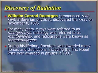
4. Copyright 2003, Elsevier Science (USA). All rights reserved.
Discovery of Radiation
Wilhelm Conrad Roentgen (pronounced rent-
ken), a Bavarian physicist, discovered the x-ray on
November 8, 1895.
For many years, x-rays were referred to as
roentgen rays, radiology was referred to as
roentgenology, and radiographs were known as
roentgenographs.
During his lifetime, Roentgen was awarded many
honors and distinctions, including the first Nobel
Prize ever awarded in physics in 1901.
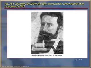
5. Copyright 2003, Elsevier Science (USA). All rights reserved.
Fig. 38-1 Roentgen, the father of x-rays, discovered the early potential of an
x-ray beam in 1895.
Fig. 38-1
6. Copyright 2003, Elsevier Science (USA). All rights reserved.
Pioneers in Dental Radiography
Otto Walkoff made the first dental radiograph.
Dr. C. Edmund Kells, a New Orleans dentist, is
credited with the first practical use of radiographs
in dentistry in 1896.
Dental radiography has progressed from these
early discoveries to the science it is today.
New technology continues to improve our
diagnostic abilities.
7. Copyright 2003, Elsevier Science (USA). All rights reserved.
Radiation Physics
All things in this world are composed of energy
and matter.
Energy is defined as the ability to do work.
Matter is anything that occupies space and has
form or shape.
8. Copyright 2003, Elsevier Science (USA). All rights reserved.
Energy
Although energy can neither be created nor
destroyed, it can change form.
Atoms contain energy.
The energy that holds the nucleus together is
called nuclear-binding energy.
The energy holding electrons, negatively charged
particles, in their shell is known as electron-binding
energy.
9. Copyright 2003, Elsevier Science (USA). All rights reserved.
Matter
Matter has many forms, including solids, liquids,
and gases.
Matter is composed of atoms grouped together in
specific arrangements called molecules.
A molecule is the smallest particle of substance
that retains the property of the original substance.
The fundamental unit of matter for discussion in
this chapter is the atom.
10. Copyright 2003, Elsevier Science (USA). All rights reserved.
Atomic Structure
The atom consists of two parts:
• a central nucleus
• orbiting electrons
An atom is identified by the composition of its
nucleus and the arrangement of its orbiting
electrons; at present, 105 different atoms exist.
11. Copyright 2003, Elsevier Science (USA). All rights reserved.
The arrangement within the atom is similar to that
of the solar system.
The atom has a nucleus as its center or sun, and
the electrons revolve (orbit) around it like planets.
The electrons remain stable in their orbit unless
disturbed or moved. X-rays can disturb the orbiting
electrons.
Atomic Structure- cont’d
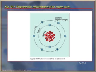
12. Copyright 2003, Elsevier Science (USA). All rights reserved.
Fig. 38-3 Diagrammatic representation of an oxygen atom.
Fig 38-3
13. Copyright 2003, Elsevier Science (USA). All rights reserved.
Nucleus
The nucleus, or dense core of the atom, is composed of
particles known as protons and neutrons.
Protons carry positive electrical charges, whereas neutrons
carry no electrical charge.
Dental x-rays do not affect the tightly bound nucleus of the
atom and are only changed in direction or scattered.
Dental x-rays cannot make atoms radioactive; thus patients
do not give off x-rays after the x-ray machine stops
producing x-rays.
14. Copyright 2003, Elsevier Science (USA). All rights reserved.
Electrons
Electrons are tiny negatively charged particles
that have very little mass.
Electrons orbit around the nucleus of an atom.
The orbit path of an electron is called an electron
shell. Each shell can contain only a specific number
of electrons.
The electrons are maintained in orbit by electron-
binding energy, a force similar to the force of
gravity on earth.
15. Copyright 2003, Elsevier Science (USA). All rights reserved.
Ionization
The electrons remain stable in their orbit around
the nucleus until x-ray photons collide with them.
(A photon is a minute bundle of pure energy that
has no weight or mass.)
X-rays have enough energy to push electrons out
of their orbits and produce ions (an atom that
gains or loses an electron and becomes electrically
unbalanced) in a process called ionization.
16. Copyright 2003, Elsevier Science (USA). All rights reserved.
Ionization- cont’d
Ionization is the process by which electrons are
removed from the orbital shells of electrically
stable atoms through collisions with x-ray photons.
When an electron is removed from the atom, an
ion pair results.
The harmful ionizing effect of x-rays in humans can
result in a disruption of cellular metabolism and
can cause permanent damage to living cells and
tissues.
17. Copyright 2003, Elsevier Science (USA). All rights reserved.
Fig. 38-4 A molecule of water (H20) consists of two atoms of hydrogen
connected to one atom of oxygen.
Fig. 38-4
18. Copyright 2003, Elsevier Science (USA). All rights reserved.
Properties of X-Rays
The dental assistant must be familiar with the
unique characteristics of x-rays.
X-rays are a form of energy that can penetrate
matter. Like visible light, radar, radio, and
television waves, they belong to a group called
electromagnetic radiation.
Electromagnetic radiation is made up of photons
that travel through space at the speed of light in a
straight line with a wavelike motion.
19. Copyright 2003, Elsevier Science (USA). All rights reserved.
Fig. 38-5 Electromagnetic spectrum, showing the various wavelengths of
commonly used radiations.
Fig. 38-5
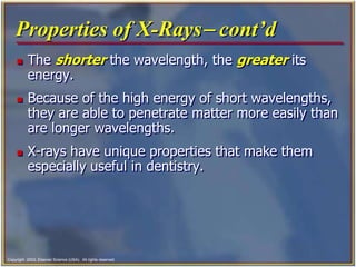
20. Copyright 2003, Elsevier Science (USA). All rights reserved.
The shorter the wavelength, the greater its
energy.
Because of the high energy of short wavelengths,
they are able to penetrate matter more easily than
are longer wavelengths.
X-rays have unique properties that make them
especially useful in dentistry.
Properties of X-Rays- cont’d
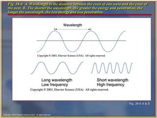
21. Copyright 2003, Elsevier Science (USA). All rights reserved.
Fig. 38-6 A, Wavelength is the distance between the crest of one wave and the crest of
the next. B, The shorter the wavelength, the greater the energy and penetration, the
longer the wavelength, the less energy and less penetration.
Fig. 38-6 A & B
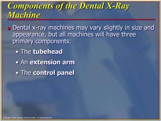
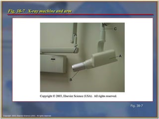
22. Copyright 2003, Elsevier Science (USA). All rights reserved.
Components of the Dental X-Ray
Machine
Dental x-ray machines may vary slightly in size and
appearance, but all machines will have three
primary components:
• The tubehead
• An extension arm
• The control panel
23. Copyright 2003, Elsevier Science (USA). All rights reserved.
Fig. 38-7 X-ray machine and arm.
Fig. 38-7
24. Copyright 2003, Elsevier Science (USA). All rights reserved.
The Tubehead
The x-ray tubehead is a tightly sealed; heavy
metal housing that contains the x-ray tube that
produces dental x-rays.
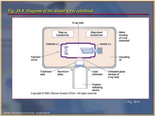
25. Copyright 2003, Elsevier Science (USA). All rights reserved.
Fig. 38-8 Diagram of the dental x-ray tubehead.
Fig. 38-8
26. Copyright 2003, Elsevier Science (USA). All rights reserved.
Components of the Tubehead
Metal housing is the metal body of the tubehead
that houses the x-ray tube. It is filled with
insulating oil.
Insulating oil surrounds the x-ray tube and
prevents overheating by absorbing the heat
created by the production of x-rays.
Tubehead seal is made of leaded glass or
aluminum, it seals the oil in the tubehead.
X-ray tube is the heart of the x-ray-generating
unit.
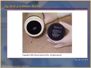
27. Copyright 2003, Elsevier Science (USA). All rights reserved.
Components of the Tubehead- cont’d
Transformer alters the voltage of incoming
electric current.
Aluminum filter is aluminum sheets of 0.5-mm
thickness.
Lead collimator is a metal disc with a small
opening in the center to control the size and shape
of the x-ray beam as it leaves the tubehead.
Position-indicating device (PID) is the open-
ended, lead-lined cylinder that extends from the
opening of the metal housing of the tubehead. It is
used to aim the x-ray beam.
28. Copyright 2003, Elsevier Science (USA). All rights reserved.
Fig. 38-10 A, Collimator. B, Filter.
Fig. 38-10 A & B
29. Copyright 2003, Elsevier Science (USA). All rights reserved.
X-Ray Tube
This vacuum environment allows the electrons to
flow with minimum resistance between the
electrodes:
• Cathode
• Anode
30. Copyright 2003, Elsevier Science (USA). All rights reserved.
Consists of a tungsten filament in a focusing cup
made of molybdenum.
The purpose of the cathode is to supply the
electrons necessary to generate x-rays.
Electrons are generated in the x-ray tube at the
cathode.
The hotter the filament becomes, the more
electrons are produced.
The Cathode
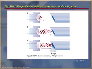
31. Copyright 2003, Elsevier Science (USA). All rights reserved.
The Anode
The anode is the target for the electrons.
It is composed of a tungsten target (a small block of
tungsten) that is embedded in the larger copper stem.
The copper around the target conducts the heat away
from the target, thus reducing the wear and tear on
the target.
The purpose of the tungsten target is to serve as a
focal spot and convert the bombarding electrons into
x-ray photons.
The x-rays at the center of this beam are known as the
central ray.
32. Copyright 2003, Elsevier Science (USA). All rights reserved.
Fig. 38-12 The production of dental x-rays occurs in the x-ray tube.
Fig. 38-12
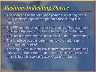
33. Copyright 2003, Elsevier Science (USA). All rights reserved.
Position-Indicating Device
The open end of the lead-lined position-indicating device
(PID) is placed against the patient’s face during film
exposure.
The PID may be cylindrical or rectangular. The rectangular
PID limits the size of the beam to that of a dental film.
PIDs used in dentistry are usually 8, 12, or 16 inches long.
The length selected is determined by the radiographic
technique being used.
The long (12 to 16 inch) PID is more effective in reducing
exposure to the patient than a short (8 inch) PID because
there is less divergence (separation) of the beam.
34. Copyright 2003, Elsevier Science (USA). All rights reserved.
Extension Arm
The extension arm encloses the wire between the
tubehead to the control panel.
It also has an important function in positioning the
tubehead.
The extension arm folds up and can be swiveled
from side to side.
If the extension arm is left in an extended position
when the machine is not in use, the weight of the
tubehead can cause it to become loose, and the
tubehead will drift (slip out of position) after it is
positioned for an exposure.
35. Copyright 2003, Elsevier Science (USA). All rights reserved.
The Control Panel
The control panel of an x-ray unit contains:
• The master switch
• Indicator light
• Exposure button
• Indicator light
• Control devices (time, milliamperage [mA]
selector, and kilovoltage [kV] selector)
A single centrally located control panel may be
used to operate several tubeheads located in
separate treatment rooms.
36. Copyright 2003, Elsevier Science (USA). All rights reserved.
How X-Rays Are Produced
The x-ray machine is plugged into the wall outlet, and
when the machine is turned on, the electric current
enters the control panel.
The current travels from the control panel to the
tubehead through electrical wires in the extension arm.
The current travels through the step-down transformer
to the filament of the cathode.
The filament circuit uses 3 to 5 volts to heat the
tungsten filament in the cathode portion of the x-ray
tube.
The heating of the filament results in thermionic
emission.
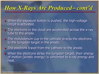
37. Copyright 2003, Elsevier Science (USA). All rights reserved.
How X-Rays Are Produced- cont’d
When the exposure button is pushed, the high-voltage
circuit is activated.
The electrons in the cloud are accelerated across the x-ray
tube to the anode.
The molybdenum cup in the cathode directs the electrons
to the tungsten target in the anode.
The electrons travel from the cathode to the anode.
When the electrons strike the tungsten target, their energy
of motion (kinetic energy) is converted to x-ray energy and
heat.
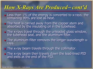
38. Copyright 2003, Elsevier Science (USA). All rights reserved.
How X-Rays Are Produced- cont’d
Less than 1% of the energy is converted to x-rays; the
remaining 99% are lost as heat.
The heat is carried away from the copper stem and
absorbed by the insulating oil in the tubehead.
The x-rays travel through the unleaded glass window,
the tubehead seal, and the aluminum filter.
The aluminum filter removes the longer-wavelength x-
rays.
The x-ray beam travels through the collimator.
The x-ray beam then travels down the lead-lined PID
and exits at the end of the PID.
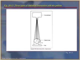
39. Copyright 2003, Elsevier Science (USA). All rights reserved.
Types of Radiation
Primary is the x-rays that come from the target of
the x-ray tube.
Secondary is x-radiation that is created when the
primary beam interacts with matter.
Scatter is a form of secondary radiation. It results
when an x-ray beam has been deflected from its
path by the interaction with matter.
40. Copyright 2003, Elsevier Science (USA). All rights reserved.
Fig. 38-13 Three types of radiation interaction with the patient.
Fig. 38-13
41. Copyright 2003, Elsevier Science (USA). All rights reserved.
Visual Characteristics
Contrast
Density
Image detail
• These qualities are necessary for a good
radiograph.
The dental assistant must understand how
variations in the character of the x-ray beam
influence the quality of the resulting radiographs.
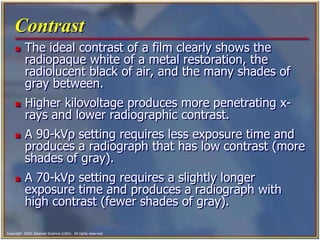
42. Copyright 2003, Elsevier Science (USA). All rights reserved.
Radiolucent and Radiopaque
Radiolucent structures allow x-rays to pass
through them.
The image of radiolucent structures appears dark
or black on the radiograph. Air spaces, soft tissues
of the body, and the dental pulp appear as
radiolucent images.
Radiopaque structures do not allow x-rays to
pass through them.
The image of radiopaque structures appears white
or light gray on the radiograph. Metal, enamel,
and dense areas of bone appear as radiopaque
images.
43. Copyright 2003, Elsevier Science (USA). All rights reserved.
Fig. 38-14 Radiolucent and radiopaque objects in a bitewing radiograph.
Fig. 38-14
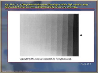
44. Copyright 2003, Elsevier Science (USA). All rights reserved.
Contrast
The ideal contrast of a film clearly shows the
radiopaque white of a metal restoration, the
radiolucent black of air, and the many shades of
gray between.
Higher kilovoltage produces more penetrating x-
rays and lower radiographic contrast.
A 90-kVp setting requires less exposure time and
produces a radiograph that has low contrast (more
shades of gray).
A 70-kVp setting requires a slightly longer
exposure time and produces a radiograph with
high contrast (fewer shades of gray).
45. Copyright 2003, Elsevier Science (USA). All rights reserved.
Density
Density is the overall blackness or darkness of a
film.
A radiograph with the correct density enables the
dentist to view black areas (air spaces), white
areas (enamel, dentin, and bone), and gray areas
(soft tissues).
The degree of density is controlled by the mAs
(milliampere seconds).
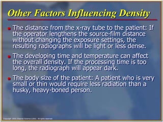
46. Copyright 2003, Elsevier Science (USA). All rights reserved.
Other Factors Influencing Density
The distance from the x-ray tube to the patient: If
the operator lengthens the source-film distance
without changing the exposure settings, the
resulting radiographs will be light or less dense.
The developing time and temperature can affect
the overall density. If the processing time is too
long, the radiograph will appear dark.
The body size of the patient: A patient who is very
small or thin would require less radiation than a
husky, heavy-boned person.
47. Copyright 2003, Elsevier Science (USA). All rights reserved.
Geometric Characteristics
There are three geometric characteristics that
affect the quality of the radiograph. These are:
• Sharpness
• Magnification
• Distortion
48. Copyright 2003, Elsevier Science (USA). All rights reserved.
Sharpness
Sharpness refers to how well the radiograph
reproduces the fine details or distinct outlines of an
object.
Sharpness is sometimes referred to as detail,
resolution, or definition.
The sharpness of an image is influenced by the
following factors:
• Focal spot size
• Film composition
• Movement
49. Copyright 2003, Elsevier Science (USA). All rights reserved.
Radiation Safety
All ionizing radiations are harmful and produce
biologic changes in living tissues.
The amount of x-radiation used in dental
radiography is small; however, biologic changes do
occur.
The dental assistant must understand how the
harmful effects of radiation occur and how to
discuss the risks of radiation with patients.
50. Copyright 2003, Elsevier Science (USA). All rights reserved.
Ionization
Ionization is the harmful effect of x-rays in humans
that can result in a disruption of cellular
metabolism and cause permanent damage to living
cells and tissues.
Ionization is the process by which electrons are
removed from electrically stable atoms through
collisions with x-ray photons.
The atoms that lose electrons become positive
ions; as such, they are unstable structures capable
of interacting with (and damaging) other atoms,
tissues, or chemicals.
51. Copyright 2003, Elsevier Science (USA). All rights reserved.
Introduction to Physiology
Functional organization of the human body.
• The cell and its function.
Genetic control of protein synthesis.
52. Copyright 2003, Elsevier Science (USA). All rights reserved.
Biologic Effects of Radiation
Exposure to radiation can bring about changes in
body chemicals, cells, tissues, and organs.
The effects of the radiation may not become
evident for many years after the time the x-rays
were absorbed.
This time lag is called the latent period.
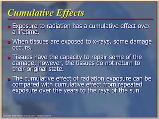
53. Copyright 2003, Elsevier Science (USA). All rights reserved.
Cumulative Effects
Exposure to radiation has a cumulative effect over
a lifetime.
When tissues are exposed to x-rays, some damage
occurs.
Tissues have the capacity to repair some of the
damage; however, the tissues do not return to
their original state.
The cumulative effect of radiation exposure can be
compared with cumulative effect from repeated
exposure over the years to the rays of the sun.
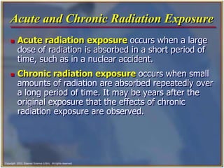
54. Copyright 2003, Elsevier Science (USA). All rights reserved.
Acute and Chronic Radiation Exposure
Acute radiation exposure occurs when a large
dose of radiation is absorbed in a short period of
time, such as in a nuclear accident.
Chronic radiation exposure occurs when small
amounts of radiation are absorbed repeatedly over
a long period of time. It may be years after the
original exposure that the effects of chronic
radiation exposure are observed.
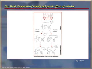
55. Copyright 2003, Elsevier Science (USA). All rights reserved.
Genetic and Somatic Effects
X-rays effect both genetic and somatic cells.
Genetic cells are the reproductive cells (sperm
and ova). Damage to genetic cells is passed on to
succeeding generations. These changes are
referred to as genetic mutations.
All other cells in the body belong to the group of
somatic tissue. (Somatic means referring to the
body.) X-rays can damage somatic tissue, but the
damage is not passed on to future generations.
56. Copyright 2003, Elsevier Science (USA). All rights reserved.
Fig. 38-16 Comparison of somatic and genetic effects of radiation.
Fig. 38-16
57. Copyright 2003, Elsevier Science (USA). All rights reserved.
Critical Organs
The following organs are considered critical
organs:
• Skin
• Thyroid gland
• Lens of the eye
• Bone marrow
58. Copyright 2003, Elsevier Science (USA). All rights reserved.
Radiation Measurements
Radiation can be measured in a manner similar to
time, distance, and weight.
Two sets of systems are used to define the way in
which radiation is measured.
The older system is referred to as the traditional
or standard system.
The newer system is the metric equivalent known
as the Systeme Internationale or SI.
59. Copyright 2003, Elsevier Science (USA). All rights reserved.
Traditional Units of Radiation
Measurement
The roentgen (R)
• The radiation absorbed dose (rad)
• The roentgen equivalent [in] man (rem)
The SI units include:
• Coulombs per kilogram (C/kg)
• The gray (Gy)
• The sievert (Sv)
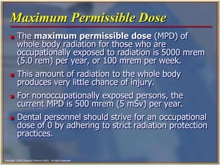
60. Copyright 2003, Elsevier Science (USA). All rights reserved.
Maximum Permissible Dose
The maximum permissible dose (MPD) of
whole body radiation for those who are
occupationally exposed to radiation is 5000 mrem
(5.0 rem) per year, or 100 mrem per week.
This amount of radiation to the whole body
produces very little chance of injury.
For nonoccupationally exposed persons, the
current MPD is 500 mrem (5 mSv) per year.
Dental personnel should strive for an occupational
dose of 0 by adhering to strict radiation protection
practices.
61. Copyright 2003, Elsevier Science (USA). All rights reserved.
Radiation Risks and Benefits
Background radiation comes from natural
sources such as radioactive materials in the ground
and cosmic radiation from space.
Exposure from medical or dental sources is an
additional radiation risk.
When dental radiographs are prescribed and
exposed, the benefit of disease detection far
outweighs the risk of biologic damage from
receiving small doses of radiation.
62. Copyright 2003, Elsevier Science (USA). All rights reserved.
Responsibilities of the Dentist
To prescribe radiographs only for diagnostic purposes.
To ensure that all radiographic equipment is properly
installed and maintained in a safe working condition.
To provide appropriate shielding to protect staff and
patients from the effects of radiation.
To require that anyone exposing radiographs be
properly trained and appropriately supervised while
exposing radiographs.
To obey all state radiographic licensing requirements,
rules, and regulations.
To participate in obtaining informed consent.
63. Copyright 2003, Elsevier Science (USA). All rights reserved.
Equipment for Radiation Protection
The dental tubehead must be equipped with
appropriate:
• Aluminium filters
• Lead collimators
• Position-indicating devices (PID)
Equipment should be checked on a regular basis by
state or federal regulating agencies.
Faulty or malfunctioning equipment should be
repaired immediately.
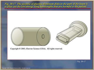
64. Copyright 2003, Elsevier Science (USA). All rights reserved.
Aluminum Filter
The purpose of the aluminum filter is to remove
the low energy, long wavelength, and least
penetrating x-rays from the x-ray beam.
These x-rays are harmful to the patient and are
not useful in producing a diagnostic-quality
radiograph.
X-ray machines operating at 70 kVp or above must
have aluminum filtration of 2.5 mm. This is a
federal requirement.
65. Copyright 2003, Elsevier Science (USA). All rights reserved.
Fig. 38-17 The purpose of placing aluminum disks in the path of the beam is
to filter out the low-energy, long wavelengths that are harmful to the patient.
Fig. 38-17
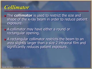
66. Copyright 2003, Elsevier Science (USA). All rights reserved.
Collimator
The collimator is used to restrict the size and
shape of the x-ray beam in order to reduce patient
exposure.
A collimator may have either a round or
rectangular opening.
A rectangular collimator restricts the beam to an
area slightly larger than a size 2 intraoral film and
significantly reduces patient exposure.
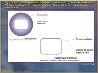
67. Copyright 2003, Elsevier Science (USA). All rights reserved.
Fig. 38-18 A, The beam produced by a circular collimator is 2.75 inches in diameter. B,
The beam produced by a rectangular collimator is just slightly larger than a size 2
intraoral film.
Fig. 38-18 A & B
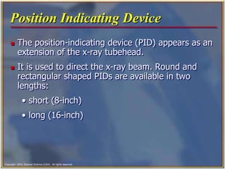
68. Copyright 2003, Elsevier Science (USA). All rights reserved.
Position Indicating Device
The position-indicating device (PID) appears as an
extension of the x-ray tubehead.
It is used to direct the x-ray beam. Round and
rectangular shaped PIDs are available in two
lengths:
• short (8-inch)
• long (16-inch)
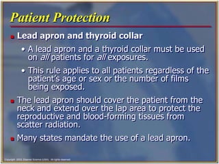
69. Copyright 2003, Elsevier Science (USA). All rights reserved.
Patient Protection
Lead apron and thyroid collar
• A lead apron and a thyroid collar must be used
on all patients for all exposures.
• This rule applies to all patients regardless of the
patient’s age or sex or the number of films
being exposed.
The lead apron should cover the patient from the
neck and extend over the lap area to protect the
reproductive and blood-forming tissues from
scatter radiation.
Many states mandate the use of a lead apron.
70. Copyright 2003, Elsevier Science (USA). All rights reserved.
Fig. 38-19 The lead apron and thyroid collar must be large enough to cover
the seated patient.
Fig. 38-19
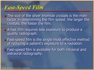
71. Copyright 2003, Elsevier Science (USA). All rights reserved.
Fast-Speed Film
The size of the silver bromide crystals is the main
factor in determining the film speed: the larger the
crystals, the faster the film.
A fast film requires less exposure to produce a
quality radiograph.
Fast-speed film is the single most effective method
of reducing a patient’s exposure to x-radiation.
Fast-speed film is available for both intraoral and
extraoral radiography.
72. Copyright 2003, Elsevier Science (USA). All rights reserved.
Film-Holding Devices
The use of a film-holding instrument keeps the
patient’s hands and fingers from being exposed to
x-radiation.
Film holders also hold the film in a stable position
and aid the operator in properly positioning the
film and the PID.
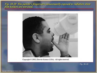
73. Copyright 2003, Elsevier Science (USA). All rights reserved.
Fig. 38-20 The patient’s fingers are unnecessarily exposed to radiation when
film holders are not used.
Fig. 38-20
74. Copyright 2003, Elsevier Science (USA). All rights reserved.
Exposure Factors
Using the proper exposure factors also limits the
amount of x-radiation exposure to the patient.
Adjusting the kilovoltage peak, milliamperage, and
time settings controls the exposure factors.
A setting of 70 to 90 kVp keeps patient exposure
to a minimum.
On some dental units, the kilovoltage peak and
milliamperage settings are preset by the
manufacturer and cannot be adjusted.
75. Copyright 2003, Elsevier Science (USA). All rights reserved.
Proper Techniques
Proper techniques are necessary to ensure the
diagnostic quality of films and reduce the amount
of exposure to a patient.
Films that are nondiagnostic must be retaken; this
results in additional radiation exposure to the
patient.
Retakes are a major cause of unnecessary
radiation to patients and must be avoided.
76. Copyright 2003, Elsevier Science (USA). All rights reserved.
X-Rays During Pregnancy
The Guidelines for Prescribing Dental
Radiographs issued by the American Dental
Association in conjunction with the Food and Drug
Administration, state that dental radiographic
procedures “do not need to be altered because of
pregnancy.”
When a lead apron is used during dental
radiographic procedures, the amount of radiation
received in the pelvic region is nearly zero.
There is no detectable exposure to the embryo or
fetus with the use of a lead apron.
77. Copyright 2003, Elsevier Science (USA). All rights reserved.
Operator Protection
A dental assistant who fails to follow the rules of
radiation protection may suffer the results of
chronic radiation exposure.
By following these rules, dental personnel can keep
their radiation exposure to zero.
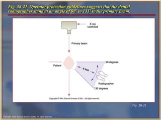
78. Copyright 2003, Elsevier Science (USA). All rights reserved.
Rules for Operator Protection
Never stand in the direct line of the primary beam.
Always stand behind a lead barrier if one is
available or a proper thickness of drywall.
If a lead barrier is not available, stand at right
angles to the beam.
Never stand closer than 6 feet to the x-ray unit
during an exposure unless you are behind a
barrier.
79. Copyright 2003, Elsevier Science (USA). All rights reserved.
Personnel Monitoring
There are 3 types of monitoring devices used to
determine the amount of radiation exposure to
personnel:
• Film badge
• Pocket dosimeter (pen style)
• Thermoluminescent (TLD)
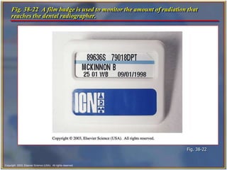
80. Copyright 2003, Elsevier Science (USA). All rights reserved.
Fig. 38-22 A film badge is used to monitor the amount of radiation that
reaches the dental radiographer.
Fig. 38-22
81. Copyright 2003, Elsevier Science (USA). All rights reserved.
Equipment Monitoring
Dental x-ray machines must be monitored for
leakage radiation.
If a dental x-ray tubehead has a faulty tubehead
seal, leakage radiation results.
Dental x-ray equipment can be monitored through
the use of a film device that can be obtained from
the manufacturer or from the state health
department.
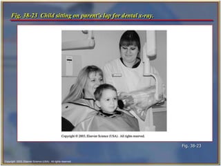
82. Copyright 2003, Elsevier Science (USA). All rights reserved.
If the Patient Cannot Cooperate
If the patient is a child who is unable to cooperate,
the child is seated on the parent’s lap in the dental
chair. Both the parent and child are covered with
the lead apron, and the parent holds the film in
place.
83. Copyright 2003, Elsevier Science (USA). All rights reserved.
Fig. 38-23 Child sitting on parent’s lap for dental x-ray.
Fig. 38-23
84. Copyright 2003, Elsevier Science (USA). All rights reserved.
ALARA Concept
The ALARA concept states that all exposure to
radiation must be kept to a minimum, or “as low
as reasonably achievable.”
Every possible method of reducing exposure to
radiation should be used to minimize risk.
The radiation protection measures detailed in this
chapter should be used to minimize patient,
operator, and staff exposure, thus keeping
radiation exposure “as low as reasonably
achievable.”
85. Copyright 2003, Elsevier Science (USA). All rights reserved.
Patient Questions
Patients often have questions and concerns about
radiation.
As a dental assistant you must be prepared to
answer their questions and educate the dental
patient about the importance of radiographs.
86. Copyright 2003, Elsevier Science (USA). All rights reserved.
Patient Questions- cont’d
Listed below are some examples of comments you can
make to patients during informal discussions.
• “The doctor orders x-rays based on your individual
needs.”
• “Our office takes every step possible to protect you
from unnecessary radiation.”
• “We use a lead apron and thyroid collar to protect
your body from stray radiation.”
• “We use a high speed film that requires only
minimal amounts of radiation.”
• Do you have any questions before we begin?”
87. Copyright 2003, Elsevier Science (USA). All rights reserved.
Fig. 38-21 Operator protection guidelines suggests that the dental
radiographer stand at an angle of 90˚ to 135˚ to the primary beam.
Fig. 38-21
88. Copyright 2003, Elsevier Science (USA). All rights reserved.
Fig. 38-15 A, A film produced with lower kilovoltage exhibits high contrast; many
light and dark areas are seen as demonstrated by the use of a stepwedge.
Fig. 38-15 A
89. Copyright 2003, Elsevier Science (USA). All rights reserved.
Fig. 38-15 B, A film produced with higher kilovoltage exhibits low contrast;
many shades of gray are seen instead of black and white.
Fig. 38-15 B