


DESIGN OF SOLID TRANSMISSION SHAFT
- 1. By ANIMESH BHATTACHARYA CLASS ROLL: Dx- 03 EXAM. ROLL: 111210003 Semester: 6th Dept.: Mechanical Engineering
- 2. What is a Transmission Shaft? - It refers to a rotating machine element, circular in cross-section, which supports transmission elements like gears, pulleys and sprockets and transmits power. - In the industries, usually ‘stepped shaft’ is used.
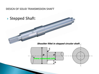
- 4. Characteristics of Stepped Shaft: A shaft is always stepped with maximum diameter in the middle and minimum diameter at the two ends, where bearings are mounted. The steps on the shaft provide shoulders for positioning transmission elements like gears, pulleys and bearings.
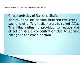
- 5. Characteristics of Stepped Shaft: The rounded-off portion between two cross- sections of different diameters is called fillet. The fillet radius is provided to reduce the effect of stress-concentration due to abrupt change in the cross-section.
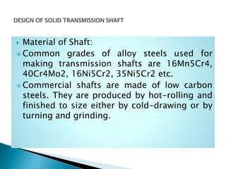
- 6. Material of Shaft : Ordinary transmission shafts are made of medium carbon steels with a carbon content from 0.15 to 0.40% such as 30C8 or 40C8. These steels are commonly called machinery steels. For the requirement of higher strength, high carbon steels such as 45C8 or 50C8 or alloy steels are employed.
- 7. Material of Shaft: Common grades of alloy steels used for making transmission shafts are 16Mn5Cr4, 40Cr4Mo2, 16Ni5Cr2, 35Ni5Cr2 etc. Commercial shafts are made of low carbon steels. They are produced by hot-rolling and finished to size either by cold-drawing or by turning and grinding.
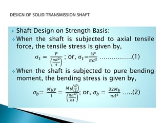
- 8. Shaft Design on Strength Basis: When the shaft is subjected to axial tensile force, the tensile stress is given by, σ 𝑡 = 𝑃 𝜋𝑑2 4 ; or, σ 𝑡= 4𝑃 𝜋𝑑2 …………….(1) When the shaft is subjected to pure bending moment, the bending stress is given by, 𝜎 𝑏= 𝑀 𝑏 𝑦 𝐼 = 𝑀 𝑏 𝑑 2 𝜋𝑑4 64 ; or, 𝜎 𝑏 = 32𝑀 𝑏 𝜋𝑑3 …..(2)
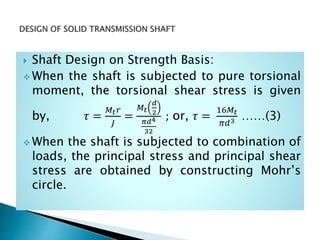
- 9. Shaft Design on Strength Basis: When the shaft is subjected to pure torsional moment, the torsional shear stress is given by, 𝜏 = 𝑀𝑡 𝑟 𝐽 = 𝑀𝑡 𝑑 2 𝜋𝑑4 32 ; or, 𝜏 = 16𝑀𝑡 𝜋𝑑3 ……(3) When the shaft is subjected to combination of loads, the principal stress and principal shear stress are obtained by constructing Mohr’s circle.
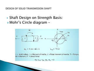
- 10. Shaft Design on Strength Basis: Mohr’s Circle diagram –
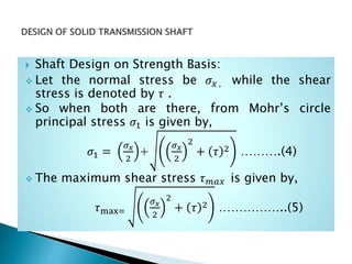
- 11. Shaft Design on Strength Basis: Let the normal stress be 𝜎 𝑥 , while the shear stress is denoted by 𝜏 . So when both are there, from Mohr’s circle principal stress 𝜎1 is given by, 𝜎1 = 𝜎 𝑥 2 + 𝜎 𝑥 2 2 + 𝜏 2 ……….(4) The maximum shear stress 𝜏 𝑚𝑎𝑥 is given by, 𝜏max= 𝜎 𝑥 2 2 + 𝜏 2 ……………..(5)
- 12. Shaft Design on Strength Basis: Equations (1) to (5) are fundamental equations for design of shafts. A shaft can be designed on the basis of maximum principal stress theory or maximum shear stress theory. We shall apply these theories to transmission shafts subjected to combined bending and torsional moments.
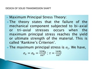
- 13. Maximum Principal Stress Theory: The theory states that the failure of the mechanical component subjected to bi-axial or tri-axial stresses occurs when the maximum principal stress reaches the yield or ultimate strength of the material. This is called ‘Rankine’s Criterion’. The maximum principal stress is 𝜎1. We have, 𝜎𝑥 = 𝜎 𝑏 = 32𝑀 𝑏 𝜋𝑑3 ; 𝜏 = 16𝑀𝑡 𝜋𝑑3
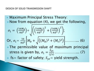
- 14. Maximum Principal Stress Theory: Now from equation (4), we get the following, 𝜎1 = 16𝑀 𝑏 𝜋𝑑3 + 16𝑀 𝑏 𝜋𝑑3 2 + 16𝑀𝑡 𝜋𝑑3 2 ; Or, 𝜎1= 16 𝜋𝑑3 𝑀 𝑏 + 𝑀 𝑏 2 + 𝑀𝑡 2 ………... (6) The permissible value of maximum principal stress is given by, 𝜎1 = 𝑆 𝑦𝑡 𝑓𝑠 ………………... (7) fs= factor of safety; 𝑆 𝑦𝑡= yield strength.
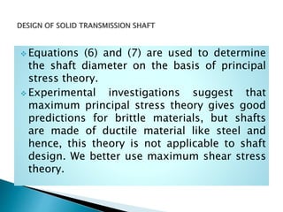
- 15. Equations (6) and (7) are used to determine the shaft diameter on the basis of principal stress theory. Experimental investigations suggest that maximum principal stress theory gives good predictions for brittle materials, but shafts are made of ductile material like steel and hence, this theory is not applicable to shaft design. We better use maximum shear stress theory.
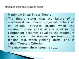
- 16. Maximum Shear Stress Theory: The theory states that the failure of a mechanical component subjected to bi-axial or tri-axial stresses occurs when the maximum shear stress at any point in the component becomes equal to the maximum shear stress in the standard specimen of the tension test, when yielding starts. This is called ‘Tresca’s Criterion’. The maximum shear stress is 𝜏 𝑚𝑎𝑥.
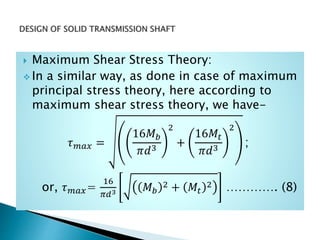
- 17. Maximum Shear Stress Theory: In a similar way, as done in case of maximum principal stress theory, here according to maximum shear stress theory, we have- 𝜏 𝑚𝑎𝑥 = 16𝑀 𝑏 𝜋𝑑3 2 + 16𝑀𝑡 𝜋𝑑3 2 ; or, 𝜏 𝑚𝑎𝑥= 16 𝜋𝑑3 𝑀 𝑏 2 + 𝑀𝑡 2 …………. (8)
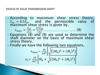
- 18. According to maximum shear stress theory, 𝑆𝑠𝑦 = 0.5𝑆 𝑦𝑡 and the permissible value of maximum shear stress is given by, 𝜏 𝑚𝑎𝑥 = 𝑆 𝑠𝑦 𝑓𝑠 = 0.5𝑆 𝑦𝑡 𝑓𝑠 ……………………… (9) Equations (8) and (9) are used to determine the shaft diameter on the basis of maximum shear stress theory. Finally we have the following two equations, 𝜏 𝑚𝑎𝑥= 16 𝜋𝑑3 𝑀 𝑏 2 + 𝑀𝑡 2 𝜎1= 16 𝜋𝑑3 𝑀 𝑏 + 𝑀 𝑏 2 + 𝑀𝑡 2
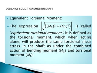
- 19. Equivalent Torsional Moment: The expression 𝑀 𝑏 2 + 𝑀𝑡 2 is called ‘equivalent torsional moment’. It is defined as the torsional moment, which when acting alone, will produce the same torsional shear stress in the shaft as under the combined action of bending moment (𝑀 𝑏) and torsional moment (𝑀𝑡).
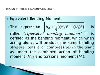
- 20. Equivalent Bending Moment: The expression 𝑀 𝑏 + 𝑀 𝑏 2 + 𝑀𝑡 2 is called ‘equivalent bending moment’. It is defined as the bending moment, which when acting alone, will produce the same bending stresses (tensile or compressive) in the shaft as under the combined action of bending moment (𝑀 𝑏) and torsional moment (𝑀𝑡).
- 21. The concept of equivalent torsional moment is used in the design of shafts on the basis of maximum shear stress theory of failure. The concept of equivalent bending moment is used in the design of shafts on the basis of maximum principal stress theory of failure.
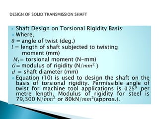
- 22. Shaft Design on Torsional Rigidity Basis: A transmission shaft is said to be rigid on the basis of torsional rigidity, if it does not twist too much under the action of an external torque. Similarly, the transmission shaft is said to be rigid on the basis of lateral rigidity, if it does not deflect too much under the action of external forces and bending moment. In some applications, like machine tool spindles, it is necessary to design the shaft on the basis of torsional rigidity, i.e., on the basis of permissible angle of twist per metre length of shaft.
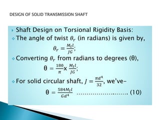
- 23. Shaft Design on Torsional Rigidity Basis: The angle of twist 𝜃𝑟 (in radians) is given by, 𝜃𝑟 = 𝑀𝑡 𝑙 𝐽𝐺 ; Converting 𝜃𝑟 from radians to degrees (θ), θ = 180 𝜋 x 𝑀𝑡 𝑙 𝐽𝐺 ; For solid circular shaft, 𝐽 = 𝜋𝑑4 32 , we’ve- θ = 584𝑀𝑡 𝑙 𝐺𝑑4 ……………….……. (10)
- 24. Shaft Design on Torsional Rigidity Basis: Where, 𝜃 = angle of twist (deg.) 𝑙 = length of shaft subjected to twisting moment (mm) 𝑀𝑡= torsional moment (N-mm) G = modulus of rigidity (N/𝑚𝑚2 ) d = shaft diameter (mm) Equation (10) is used to design the shaft on the basis of torsional rigidity. Permissible angle of twist for machine tool applications is 0.25 𝑜 per metre length. Modulus of rigidity for steel is 79,300 N/𝑚𝑚2 or 80kN/𝑚𝑚2(approx.).
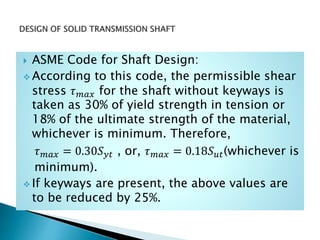
- 25. ASME Code for Shaft Design: According to this code, the permissible shear stress 𝜏 𝑚𝑎𝑥 for the shaft without keyways is taken as 30% of yield strength in tension or 18% of the ultimate strength of the material, whichever is minimum. Therefore, 𝜏 𝑚𝑎𝑥 = 0.30𝑆 𝑦𝑡 , or, 𝜏 𝑚𝑎𝑥 = 0.18𝑆 𝑢𝑡(whichever is minimum). If keyways are present, the above values are to be reduced by 25%.
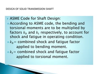
- 26. ASME Code for Shaft Design: According to ASME code, the bending and torsional moments are to be multiplied by factors 𝑘 𝑏 and 𝑘 𝑡 respectively, to account for shock and fatigue in operating condition. 𝑘 𝑏= combined shock and fatigue factor applied to bending moment. 𝑘 𝑡= combined shock and fatigue factor applied to torsional moment.
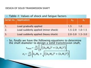
- 27. Table-1: Values of shock and fatigue factors So, finally we have the following equations to determine the shaft diameter to design a solid transmission shaft, 𝜏 𝑚𝑎𝑥= 16 𝜋𝑑3 𝑘 𝑏 𝑀 𝑏 2 + 𝑘 𝑡 𝑀𝑡 2 𝜎1= 16 𝜋𝑑3 𝑘 𝑏 𝑀 𝑏 + 𝑘 𝑏 𝑀 𝑏 2 + 𝑘 𝑡 𝑀𝑡 2 Serial no. Application 𝒌 𝒃 𝒌 𝒕 1. Load gradually applied 1.5 1.0 2. Load suddenly applied (minor shock) 1.5-2.0 1.0-1.5 3. Load suddenly applied (heavy shock) 2.0-3.0 1.5-3.0