Distillation Column Design
•Download as PPTX, PDF•
37 likes•39,333 views

An overview of distillation column design concepts and major design considerations. Explains distillation column design concepts, what you would provide to a professional distillation column designer, and what you can expect back from a distillation system design firm. To speak with an engineer about your distillation column project, call EPIC at 314-207-4250.
Report
Share

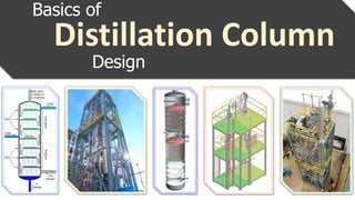

Distillation Column Design
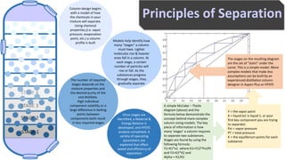
- 2. Principles of Separation The stages on the resulting diagram are the set of “stairs” under the curve. This is a simple model. More complex models that make less assumptions can be built by an experienced distillation column designer in Aspen Plus or HYSYS Y = the vapor point X = liquid (x1 is liquid 1, or your first key component you are trying to separate) Pvi = vapor pressure PT = total pressure K = the equilibrium points for each substance A simple McCabe – Theile diagram (above) and the formula below demonstrate the concept behind more complex column sizing models. The key piece of information is how many ‘stages’ a column requires to separate two substances. Stages are found by using the following formula: Y1=K1*x1 where K1=Y12*Pvi/Pt and Y2=K2*X2 and Alpha = K1/K2 The number of required stages depends on the mixture properties and the desired purity of the end distillate. High individual component volatility or a large difference in boiling points between components both result in less required stages Column design begins with a model of how the chemicals in your mixture will separate. Using chemical properties,(i.e. vapor pressure, evaporation point, etc.) a column profile is built Models help identify how many “stages” a column must have. Lighter molecules rise & heavier ones fall in a column. At each stage, a certain number of particles will rise or fall. As the substances progress through stages, they gradually separate Once stages are identified, a Material & Energy Balance is developed, and HYSYS analysis completed. A variety of operating parameters are explored that effect speed and efficiency of separation STAGE 1 STAGE 2 STAGE 3 STAGE 4
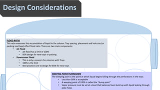
- 3. Explain this section in a few sentences concisely and clearly. Design Considerations FLOOD RATIO This ratio measures the accumulation of liquid in the column. Tray spacing, placement and hole size (or packing size/type) effect flood ratio. There are two main components: • Jet Flood • Jet flood has a limit of 100% • 85% design for new trays or packing • Downcomer Flood • This is only a concern for columns with Trays • 100% is the limit • Best practices are to design for 85% for new trays WEEPING POINT/TURNDOWN The weeping point is the point at which liquid begins falling through the perforations in the trays • Less than 50% is acceptable • A weeping point of 100% is called the “dump point” • Vapor pressure must be set at a level that balances foam build up with liquid leaking through plate holes
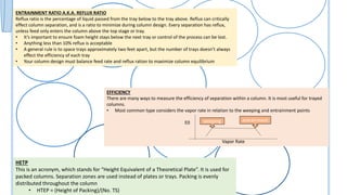
- 4. Explain this section in a few sentences concisely and clearly. EFFICIENCY There are many ways to measure the efficiency of separation within a column. It is most useful for trayed columns. • Most common type considers the vapor rate in relation to the weeping and entrainment points E0 Vapor Rate weeping entrainment ENTRAINMENT RATIO A.K.A. REFLUX RATIO Reflux ratio is the percentage of liquid passed from the tray below to the tray above. Reflux can critically effect column separation, and is a ratio to minimize during column design. Every separation has reflux, unless feed only enters the column above the top stage or tray. • It’s important to ensure foam height stays below the next tray or control of the process can be lost. • Anything less than 10% reflux is acceptable • A general rule is to space trays approximately two feet apart, but the number of trays doesn’t always effect the efficiency of each tray • Your column design must balance feed rate and reflux ration to maximize column equilibrium HETP This is an acronym, which stands for “Height Equivalent of a Theoretical Plate”. It is used for packed columns. Separation zones are used instead of plates or trays. Packing is evenly distributed throughout the column • HTEP = (Height of Packing)/(No. TS)
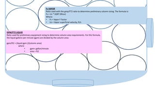
- 5. GPM/FT2 LIQUID Ratio used for preliminary equipment sizing to determine column area requirements. For this formula, the liquid gallons-per-minute (gpm) are divided by the column area: gpm/ft2 = (liquid gpm )/(column area) where • gpm= gallon/minute • area = ft2 Fs VAPOR Ratio used with the gmp/FT2 ratio to determine preliminary column sizing. The formula is: Fs = Us * SQRT (Rhov) Where: • Fs = Vapor F Factor • Us = Vapor superficial velocity, ft/s
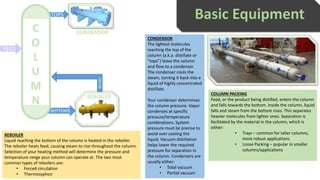
- 6. Basic Equipment BOTTOMS FEED TOPS RECIRC C O L U M N CONDENSOR REBOILER COLUMN PACKING Feed, or the product being distilled, enters the column and falls towards the bottom. Inside the column, liquid falls and steam from the bottom rises. This separates heavier molecules from lighter ones. Separation is facilitated by the material in the column, which is either: • Trays – common for taller columns, more robust applications • Loose Packing – popular in smaller columns/applications CONDENSOR The lightest molecules reaching the top of the column (a.k.a. distillate or “tops”) leave the column and flow to a condenser. The condenser cools the steam, turning it back into a liquid of highly concentrated distillate. Your condenser determines the column pressure. Vapor condenses at specific pressure/temperature combinations. System pressure must be precise to avoid over cooling the liquid. Vacuum distillation helps lower the required pressure for separation in the column. Condensers are usually either: • Total vacuum • Partial vacuum REBOILER Liquid reaching the bottom of the column is heated in the reboiler. The reboiler heats feed, causing steam to rise throughout the column. Selection of your heating method will determine the pressure and temperature range your column can operate at. The two most common types of reboilers are: • Forced circulation • Thermosyphon
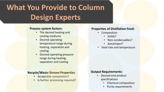
- 7. Explain this section in a few sentences concisely and clearly.What You Provide to Column Design Experts Properties of Distillation Feed: • Composition • Solids? • Non-condensables? • Azeotropes? • Feed rate and temperature Output Requirements: • Desired end product specifications • Chemical composition • Purity requirements Process system factors: • The desired heating and cooling mediums • Desired operating temperature range during heating, separation and cooling • Desired operating pressure range during heating, separation and cooling Recycle/Waste Stream Properties • Acceptable composition? • Is further processing required?
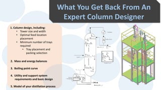
- 8. Explain this section in a few sentences concisely and clearly.What You Get Back From An Expert Column Designer 1. Column design, including: • Tower size and width • Optimal feed location placement • Minimum number of trays required • Tray placement and packing selection 2. Mass and energy balances 3. Boiling point curve 4. Utility and support system requirements and basic design 5. Model of your distillation process
- 9. Created by Need expert distillation column design or fabrication? Speak with an experienced distillation system designer today: (314) 845-0077 www.epicmodularprocess.com/distillation MODULAR PROCESS SYSTEMS