Location via proxy:   [ UP ]  
[Report a bug]   [Manage cookies]                
SlideShare a Scribd company logo
DRAINAGE AND IRRIGATION
ENGINEERING
BY
PROF. JK ADEWUMI
INTRODUCTION
COURSE GOALS



This course has two specific goals:
(i) To introduce students to basic concepts
of soil, water, plants, their interactions, as well
as irrigation and drainage systems design,
planning and management.
(ii) To develop analytical skills relevant to the
areas mentioned in (i) above, particularly the
design of irrigation and drainage projects.
Course Outline







Basic Soil-Plant-Water Relations.
Irrigation Water Requirements,
Sources, quantity and quality of irrigation
water:
Irrigation planning, scheduling and
efficiencies.
Design of irrigation systems and structures.
Design of drainage systems and structures.
Computer applications and simulation
modeling.
Course Objectives




On Completion of this course, students
should be able to:
(i) Understand the basic soil-plant-water
parameters related to irrigation
(ii) Understand how to estimate the quantity
of water required by crops using manual and
computer methods.
(iii) Be able to plan and design irrigation and
drainage projects.
COURSE OBJECTIVES CONTD.



(iv) Understand the computer applications in
irrigation and drainage designs.
(v) Design channels and other irrigation
structures required for irrigation, drainage, soil
conservation, flood control and other water-
management projects.
Course Assessment



(i) One (1) mid-semester test, 1-hour
duration counting for 10% of the total
course.
(ii)One (1) Project Assignment
counting for 10%.
One (1) end-of-semester examination, 2
hours duration counting for 80% of the
total course marks.
Reading Materials




(i) James, L.G. (1988). Principles of Farm
Irrigation System Design. John Wiley, New
York.
(ii) Chin, D.A.. (2000). Water Resources
Engineering, Prentice Hall, New Jersey.
(iii) Journal of Irrigation and Drainage
Engineering, American Society of Civil
Engineers.
(iv) Course comprehensive note book and
other handouts and tutorial sheets.
DRAINAGE AND IRRIGATION
ENGINEERING
1.1.Irrigation is the application of water to the
soil to supplement natural precipitation and
provide an environment that is optimum for
crop production.
TYPES OF IRRIGATION


SUPPLEMENTARY IRRIGATION: IN
AREAS WITH RAINFALL FOR A PART OF
THE SEASON OR YEAR
TOTAL IRRIGATION: IN AREAS OF NO
RAINFALL
OBJECTIVES OF IRRIGATION




To Supply Water
Partially or Totally
for Crop Need
To Cool both the
Soil and the Plant
To Leach Excess
Salts
To improve
Groundwater
storage


To Facilitate
continuous cropping
To Enhance
Fertilizer
Application-
Fertigation
To Understand Irrigation, One
Needs Knowledge of:




Basic Soil Science/
Physics
Plants
Water
Plant/Soil/Water
Relations



Hydraulics
Hydrology
General Engineering
Principles
1.2 SOIL CONSTITUENTS




Mineral Material: Sand, clay and silt
Organic matter - very valuable
Water
Air
PROPORTIONS OF SOIL
CONSTITUENTS
45%
5%
30%
20%
M I N E R A L S
O M
W ater
A ir
MINERAL COMPONENTS


Except in the case of organic soils,
most of a soil’s solid framework
consists of mineral particles.
They are variable in size and
composition. They can vary from small
rock particles to colloids.
MINERAL COMPONENT CONTD.


The mineral can be raw quartz and other
primary materials – coarse fractions which
have not changed from parent material)
They can also be silicate clays and iron
oxides formed by the breakdown and
weathering of less resistant minerals as soil
formation progressed. These are called
secondary minerals.
MINERAL CONSTITUENTS
USDA ISSS
ROCKS > 2 mm > 2 mm
SAND 0.05 to 2 mm 0.02 to 2 mm
SILT 0.002 to 0.05
mm
0.002 to 0.02
mm
CLAY < 0.002 mm < 0.002 mm
SAND COMPONENT



Visible to the Naked Eye and Vary in
Size.
They are Gritty when rubbed between
Fingers.
Sand Particles do not Adhere to one
another and are therefore not Sticky.
SILT AND CLAY COMPONENTS
Silt Particles aresmaller than sand. The
silt particles are too small to be seen without
a microscope. It feels smooth but not sticky,
even when wet.
Clays are the smallest class of mineral
particles. They adhere together to form a
sticky mass when wet and form hard clods
when dry.
SOIL TEXTURE



Relative proportions of the various soil
separates (sand, silt and clay) in a soil.
Terms such as sandy loam, silty clay,
and clay loam are used to identify soil
texture.
Soil Components are separated using
Mechanical Analysis, Sieving for Sand
and Rate of Settling in Pipette for Silt
and Clay.
SOIL TEXTURE CONTD.



From the mechanical analysis, the proportions of
sand, silt and clay are obtained.
The actual soil texture is determined using the Soil
Textural Triangle e.g. for a Soil with 50% sand, 20%
silt and 30% clay, the texture is Sandy Clay Loam.
Arranged in the increasing order of heaviness, there
are 12 soil textures namely: sand, loamy sand, sandy
loam, loam, silt loam, silt, sandy clay loam, silty clay
loam, clay loam, sandy clay, silty clay and clay.
Ekwe Chapter1 JK Adewunmi.pdf
1.4 COLLOIDAL MATERIAL


The smaller particles (< 0.001 mm) of clay
and similar sized organic particles) have
colloidal properties and can be seen with an
electronic microscope.
The colloidal particles have a very large area
per unit weight so there are enough surface
charges to which water and ions can be
attracted. These charges make them adhere
together. Humus improves the water holding
capacity of the soil.
1.5 WATER



Quantity of water in a soil as
determined by its moisture content
does not give a true indication of the
soil ‘wetness’.
A clay soil, which on handling feels dry,
can be at the same moisture content as
a sandy soil, which feels wet.
A plant will have less difficulty
extracting water from a sandy soil than
from a clay soil at the same moisture
content.
SOIL WATER CONTD.


There is need for a soil ‘wetness’ which
reflects the ease or difficulty of
extraction of water from the soil by the
plant.
The Concept of Soil Water Potential is
therefore used in Soil/Plant/Water
Relations
1.5.1. Mechanism of Soil
Water Movement


The flow of water in any hydraulic
system, including the soil-plant-water
system, takes place from a state of
higher to one of lower potential energy.
The steepness of the potential gradient
from one point in the system reflects
the ease with which water will flow
down the potential gradient between the
points.
1.5.2 Components of Soil
Water Potential

As in any other hydraulic system, the
total potential (or total hydraulic head)
in the soil-water system is made up of a
number of distinguishable components.
Some of these are as follows:
i ) Gravitational Potential: Reflects
gravitational forces on the soil water.
Components of Soil Water
Potential Contd.


ii) Pressure Potential: This is positive when
greater than atmospheric pressure, and
negative when below atmospheric.
A negative pressure potential (or tension, or
suction) is also known as the matric potential.
It is characteristic of soil water above a free
water surface.
Components of Soil Water
Potential Contd.


iii) Osmotic Potential: reflects the effect of
solutes in soil water, in the presence of a
semi-permeable membrane
The total potential of soil water at a point is
the sum of all the components of potential,
which are acting. Note that the movement of
water in the soil is slow, so kinetic energy is
neglected.
1.5.3Soil Water Potential and
Soil Water Content:


If a water pressure less that atmospheric
(usually referred to as suction) is applied to a
saturated soil, some water will drain off until
equilibrium is reached.
At this state of equilibrium, the total potential
of the soil water relative to a free water
surface at the same elevation will be negative.
Its value is known as the soil suction or matric
suction since it is equal to the negative
pressure potential of the soil water.
Soil Water Potential and Soil
Water Content Contd.



As the pressure potential is reduced ( i.e.
suction increased) more water is removed
from the soil.
The relationship between suction and actual
water content is referred to as soil water
characteristic.
Soil Water Potential is normally measured by
tensiometers (matric potential), hanging
water column (sand box) and pressure
chamber.
Ekwe Chapter1 JK Adewunmi.pdf
1.5.4 Methods of Measuring Soil
Water Content


i)By Feel: This is by far the easiest method.
Assessment by feel is good for experienced
people who have sort of calibrated their
hands. The type of soil is important.
ii) Gravimetric Method: This is equal to:
w
m
s
M M ass of W ater
P
M M ass of D r y Solids
 
Gravimetric Method Contd.
 Weigh wet soil in a container, put in
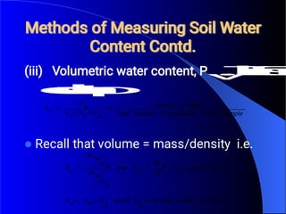
oven at 105 oC for about 48 hours;
weigh again and obtain the weight of
water by subtraction. A good soil
should have moisture contents between
5 and 60% and for peat or organic soils,
it can be greater than 100%.
Methods of Measuring Soil Water
Content Contd.

(iii) Volumetric water content, Pv
.
T
h
i
s
i
s
e
q
u
a
l
t
o
:
Recall that volume = mass/density i.e.
Sample
Soil
d
Undisturbe
of
Volume
Total
Water
of
Volume
w
V
a
V
s
V
w
V
v
P 



soil
the
of
density
bulk
the
is
b
D
where
b
D
x
m
P
v
P
w
D
ce
b
D
x
s
M
w
M
v
P
and
b
D
s
M
w
D
w
M
v
P



 1
sin
Soil Bulk Density





Bulk Density, Db
i
s
d
e
fi
n
e
d
a
s
t
h
e
m
a
s
s
o
f
a
u
n
i
t
v
o
l
u
m
e
o
f
d
r
y
s
o
i
l
.
This includes both solids and pores.
i.e. bulk density = Ms
/
V
;
Ms
i
s
t
h
e
m
a
s
s
o
f
d
r
y
s
o
i
l
a
n
d
V
i
s
t
h
e
t
o
t
a
l
v
o
l
u
m
e
o
f
u
n
d
i
s
t
u
r
b
e
d
s
o
i
l
.
The major method of measuring bulk density in the
field is to collect a known volume of undisturbed soil
(V) in a soil core, and drying it in the oven to remove
all the water to obtain Ms
.
Methods of Measuring Soil Water
Content Contd.






(iv) Neutron Probe: It consists of a probe lowered down a hole
in the soil.
A box (rate meter or rate scalar) is at the top.
Within the probe is a radioactive source e.g. beryllium (435
years life span).
Close to the source is a detector.
The source emits fast neutrons, some of which are slowed
down when they collide with water molecules (due to hydrogen
molecules).
A cloud of slow neutrons (thermal neutrons) build up near the
probe and are registered by the rate meter or rate scalar which
measures the number of slowed down neutrons.
NEUTRON PROBE
Fig. 1.3: Diagram and Photograph of Neutron Probe in Use
The method is quick but very expensive.
It is also dangerous since it is radioactive and must be used with care.
1.5.5 Methods of Measuring
Soil Water Suction





i) Electrical Resistance Unit: This consists of a porous body
with two electrodes embedded into it.
The porous body when buried equilibrates with the soil water
and the readings are obtained through the resistance meters
attached to the electrodes.
Resistance units are measured and the instrument needs to be
calibrated against matric suction or volumetric moisture
content (Pv).
Various porous bodies needed are gypsum, nylon or fibreglass.
The instrument is relatively cheap but it takes a long time to
equilibrate or react e.g. 48 hours. The method is insensitive in
wet soils <0.5 bars. It measures from 0.5 to 15 bars and more.
ELECTRICAL RESISTANCE UNIT
Figure 1.4 Portable meter and resistance blocks used to measure
soil moisture.
(Courtesy Industrial Instrument, Inc.)
Methods of Measuring Soil
Water Suction Contd.



ii) Tensiometer: Tensiometer operates on the principle that a
partial vacuum is developed in a closed chamber when water
moves out through the porous ceramic tip to the surrounding.
A vacuum gauge or a water or mercury manometer can
measure the tension. The gauge is usually calibrated in
centibars or millibars.
After the porous cup is put in the soil, the tensiometer is filled
with water. Water moves out from the porous tip to the
surrounding soil (as suction is more in the soil). A point is
reached when the water in the tensiometer is at equilibrium
with the soil water. The reading of the gauge is then taken and
correlated to moisture content using a calibration curve.
Ekwe Chapter1 JK Adewunmi.pdf
1.5.6 Soil Water Equilibrium
Points


In a soil, which is completely saturated,
large pores are filled with what is called
gravitational water because it can drain
out under gravity.
It drains out so fast that it is not
available to the crops. The time of
draining out varies from one day in
sandy soils to four days in clay soils.
Soil Water Equilibrium Points
Contd.




Field Capacity (FC): This is the amount of water a well-drained
soil contains after gravitational water movement has materially
ceased.
It is taken as the water content after 48 hours the soil has been
subjected to heavy rainfall or irrigation sufficient to cause
saturation.
Field capacity can also be determined by finding the moisture
content when suction is 1/3 bar for clay and 1/10 bar for sand.
There still remains the water held loosely between the soil
particles by surface tension at field capacity. This is called
capillary water and is the main source of water for plant growth.
Plants continuously take this up until there is no more water
available for crop growth and wilting occurs.
SOIL MOISTURE EQUILIBRIUM
POINTS CONTD.



Permanent Wilting Point (PWP): This is the
soil moisture content at which crops can no
longer obtain enough water to satisfy
evapotranspiration needs.
The plant will wilt and may die later if water is
not available. Water tension of soil at PWP is
generally taken as 15 bars.
For field estimation, a crop is planted and
when it wilts, the moisture content is the PWP.
This technique requires personal judgment
and prone to mistakes.
SOIL MOISTURE EQUILIBRIUM
POINTS CONTD.


Available Water (AW): This is the water
available to crops. It is the water content at
field capacity minus that at permanent wilting
point.
Readily Available Water (RAW): This is the
level to which the available water in the soil
can be used up without causing stress in the
crop. For most crops, 50 to 60% available
water is taken as readily available.
Typical Soil Water Equilibrium
Points
Field
Capacity
(FC)
(By Weight)
Permanent
Wilting
Point (PWP)
(By Weight)
Available
Water (AW)
Readily
Available
Water = 0.5
AW
Clay 45 30 15 7.5
Clay Loam 40 25 15 7.5
Fine Sand 15 8 7 3.5
Sand 8 4 4 2.0
Available Water in the Soil
Saturated
Field
Capacity
Wilting Point
Available
Water
•Excess
water
100% available
Readily Available Water
•Little reserve
available
and plants stressed
0% Available
Oven dry
•No water available
1.5.7 DEFINITION OF SOIL WETNESS

a)



Soil Wetness can be described as:
By Mass (Pm): This is the gravimetric system.
b) By Volume (Pv): This is the volumetric system. It is given as:
Pv
=
P
m
x
D
r
y
b
u
l
k
d
e
n
s
i
t
y
(
D
b
)
.
c) By Equivalent Depth: This is expressed in depth eg. in mm.
This is normally used in irrigation engineering.
d = Pm
.
D
b
.
D
where: d is the equivalent depth of water applied (mm);
Pm
i
s
t
h
e
m
o
i
s
t
u
r
e
c
o
n
t
e
n
t
b
y
m
a
s
s
(
f
r
a
c
t
i
o
n
o
r
d
e
c
i
m
a
l
)
;
D is the root zone depth (mm). In this case, Db is the specific
gravity of the soil, which is dimensionless. It has the same
units as bulk density when expressed in gm/cm3. The unit of
Table: Effective Rooting Depth (mm) of Some
Crops
Crops Effective Rooting
Depth
Fruits 750
Lucerne 1200
Cotton 900
Maize, small grains,
wheat
600
Most Vegetables 300
Source: Hudson’s Field Engineering
1.5.8 INFILTRATION OF
WATER



Infiltration is the entry of water into the soil. It
is a very important variable in irrigation
design since it shows the rate at which water
can move into the soil mass to replenish the
root zone.
Infiltration rate of a soil is the maximum rate
at which water will enter the soil mass
through the surface.
Infiltration rates into soils depend on soil
texture and structure, density, organic matter
content, hydraulic conductivity (permeability)
and porosity.
INFILTRATION CONTD.



As wetting time increases, the infiltration rate
decreases and usually approaches a constant value,
which in the case of heavy clays may be zero. A
general equation for the Infiltration rate (I) is the
Kostiakov (1932) equation:
I = (a Tn ) mm/hr.
Where: a and n are constants and T is the elapsed
wetting time
Methods of Measuring Infiltration



Irrigation is practiced mainly in three ways:
By flooding the whole surface of the soil surface;
By Flooding part of the surface and
By Sprinkling.
The method used influences the measured intake
rate of water into the soil. When designing irrigation
systems, the method used for measuring the soil
infiltration rate should simulate, as far as possible,
the mechanism of water intake during the application.
Infiltration Measurement For
Flooded Irrigation





For Flooded irrigation (border strip and basin), a double
infiltrometer is normally used.
This consists of two concentric cylinders, the inner about 0.4 m
diameter, the outer 0.5 m.
Water is maintained at the same level in each cylinder, 25 mm
above the soil surface, or more if the water level is likely to be
higher during irrigation.
The water infiltrating from the outer ring prevents lateral
seepage by the water from the center cylinder.
By measuring the rate at which the water is added to the center
cylinder, the infiltration rate can be found.
Double Ring Infiltrometer
Infiltration Measurement For
Furrow Irrigation



For flood irrigation (furrow), in addition to the
usual factors affecting infiltration, the intake
of water depends on the spacing and shape
of the furrow.
The difference between inflows and outflows
of water flowing through hydraulic flumes
placed at different distances of test furrows
represent the total infiltration.
Furrow dimensions are used to obtain the
infiltration rates. See Chapter 3 for test
calculations.
Infiltration Measurement For
Sprinkler Irrigation




The mechanism of infiltration under sprinkler
irrigation is different from the surface methods.
There is no head of water above the soil surface and
the effect of sprinkler drops on the soil tends to form
soil pans on the surface, reducing infiltration rate.
The ideal method of measuring infiltration rates for
sprinkler irrigation is to use sprinklers at various rates
of spraying.
Water could be sprayed into infiltrometers to obtain a
small head of water and the intake rate found as
described earlier.

More Related Content

Ekwe Chapter1 JK Adewunmi.pdf

  • 2. COURSE GOALS    This course has two specific goals: (i) To introduce students to basic concepts of soil, water, plants, their interactions, as well as irrigation and drainage systems design, planning and management. (ii) To develop analytical skills relevant to the areas mentioned in (i) above, particularly the design of irrigation and drainage projects.
  • 3. Course Outline        Basic Soil-Plant-Water Relations. Irrigation Water Requirements, Sources, quantity and quality of irrigation water: Irrigation planning, scheduling and efficiencies. Design of irrigation systems and structures. Design of drainage systems and structures. Computer applications and simulation modeling.
  • 4. Course Objectives     On Completion of this course, students should be able to: (i) Understand the basic soil-plant-water parameters related to irrigation (ii) Understand how to estimate the quantity of water required by crops using manual and computer methods. (iii) Be able to plan and design irrigation and drainage projects.
  • 5. COURSE OBJECTIVES CONTD.    (iv) Understand the computer applications in irrigation and drainage designs. (v) Design channels and other irrigation structures required for irrigation, drainage, soil conservation, flood control and other water- management projects.
  • 6. Course Assessment    (i) One (1) mid-semester test, 1-hour duration counting for 10% of the total course. (ii)One (1) Project Assignment counting for 10%. One (1) end-of-semester examination, 2 hours duration counting for 80% of the total course marks.
  • 7. Reading Materials     (i) James, L.G. (1988). Principles of Farm Irrigation System Design. John Wiley, New York. (ii) Chin, D.A.. (2000). Water Resources Engineering, Prentice Hall, New Jersey. (iii) Journal of Irrigation and Drainage Engineering, American Society of Civil Engineers. (iv) Course comprehensive note book and other handouts and tutorial sheets.
  • 8. DRAINAGE AND IRRIGATION ENGINEERING 1.1.Irrigation is the application of water to the soil to supplement natural precipitation and provide an environment that is optimum for crop production.
  • 9. TYPES OF IRRIGATION   SUPPLEMENTARY IRRIGATION: IN AREAS WITH RAINFALL FOR A PART OF THE SEASON OR YEAR TOTAL IRRIGATION: IN AREAS OF NO RAINFALL
  • 10. OBJECTIVES OF IRRIGATION     To Supply Water Partially or Totally for Crop Need To Cool both the Soil and the Plant To Leach Excess Salts To improve Groundwater storage   To Facilitate continuous cropping To Enhance Fertilizer Application- Fertigation
  • 11. To Understand Irrigation, One Needs Knowledge of:     Basic Soil Science/ Physics Plants Water Plant/Soil/Water Relations    Hydraulics Hydrology General Engineering Principles
  • 12. 1.2 SOIL CONSTITUENTS     Mineral Material: Sand, clay and silt Organic matter - very valuable Water Air
  • 13. PROPORTIONS OF SOIL CONSTITUENTS 45% 5% 30% 20% M I N E R A L S O M W ater A ir
  • 14. MINERAL COMPONENTS   Except in the case of organic soils, most of a soil’s solid framework consists of mineral particles. They are variable in size and composition. They can vary from small rock particles to colloids.
  • 15. MINERAL COMPONENT CONTD.   The mineral can be raw quartz and other primary materials – coarse fractions which have not changed from parent material) They can also be silicate clays and iron oxides formed by the breakdown and weathering of less resistant minerals as soil formation progressed. These are called secondary minerals.
  • 16. MINERAL CONSTITUENTS USDA ISSS ROCKS > 2 mm > 2 mm SAND 0.05 to 2 mm 0.02 to 2 mm SILT 0.002 to 0.05 mm 0.002 to 0.02 mm CLAY < 0.002 mm < 0.002 mm
  • 17. SAND COMPONENT    Visible to the Naked Eye and Vary in Size. They are Gritty when rubbed between Fingers. Sand Particles do not Adhere to one another and are therefore not Sticky.
  • 18. SILT AND CLAY COMPONENTS Silt Particles aresmaller than sand. The silt particles are too small to be seen without a microscope. It feels smooth but not sticky, even when wet. Clays are the smallest class of mineral particles. They adhere together to form a sticky mass when wet and form hard clods when dry.
  • 19. SOIL TEXTURE    Relative proportions of the various soil separates (sand, silt and clay) in a soil. Terms such as sandy loam, silty clay, and clay loam are used to identify soil texture. Soil Components are separated using Mechanical Analysis, Sieving for Sand and Rate of Settling in Pipette for Silt and Clay.
  • 20. SOIL TEXTURE CONTD.    From the mechanical analysis, the proportions of sand, silt and clay are obtained. The actual soil texture is determined using the Soil Textural Triangle e.g. for a Soil with 50% sand, 20% silt and 30% clay, the texture is Sandy Clay Loam. Arranged in the increasing order of heaviness, there are 12 soil textures namely: sand, loamy sand, sandy loam, loam, silt loam, silt, sandy clay loam, silty clay loam, clay loam, sandy clay, silty clay and clay.
  • 22. 1.4 COLLOIDAL MATERIAL   The smaller particles (< 0.001 mm) of clay and similar sized organic particles) have colloidal properties and can be seen with an electronic microscope. The colloidal particles have a very large area per unit weight so there are enough surface charges to which water and ions can be attracted. These charges make them adhere together. Humus improves the water holding capacity of the soil.
  • 23. 1.5 WATER    Quantity of water in a soil as determined by its moisture content does not give a true indication of the soil ‘wetness’. A clay soil, which on handling feels dry, can be at the same moisture content as a sandy soil, which feels wet. A plant will have less difficulty extracting water from a sandy soil than from a clay soil at the same moisture content.
  • 24. SOIL WATER CONTD.   There is need for a soil ‘wetness’ which reflects the ease or difficulty of extraction of water from the soil by the plant. The Concept of Soil Water Potential is therefore used in Soil/Plant/Water Relations
  • 25. 1.5.1. Mechanism of Soil Water Movement   The flow of water in any hydraulic system, including the soil-plant-water system, takes place from a state of higher to one of lower potential energy. The steepness of the potential gradient from one point in the system reflects the ease with which water will flow down the potential gradient between the points.
  • 26. 1.5.2 Components of Soil Water Potential  As in any other hydraulic system, the total potential (or total hydraulic head) in the soil-water system is made up of a number of distinguishable components. Some of these are as follows: i ) Gravitational Potential: Reflects gravitational forces on the soil water.
  • 27. Components of Soil Water Potential Contd.   ii) Pressure Potential: This is positive when greater than atmospheric pressure, and negative when below atmospheric. A negative pressure potential (or tension, or suction) is also known as the matric potential. It is characteristic of soil water above a free water surface.
  • 28. Components of Soil Water Potential Contd.   iii) Osmotic Potential: reflects the effect of solutes in soil water, in the presence of a semi-permeable membrane The total potential of soil water at a point is the sum of all the components of potential, which are acting. Note that the movement of water in the soil is slow, so kinetic energy is neglected.
  • 29. 1.5.3Soil Water Potential and Soil Water Content:   If a water pressure less that atmospheric (usually referred to as suction) is applied to a saturated soil, some water will drain off until equilibrium is reached. At this state of equilibrium, the total potential of the soil water relative to a free water surface at the same elevation will be negative. Its value is known as the soil suction or matric suction since it is equal to the negative pressure potential of the soil water.
  • 30. Soil Water Potential and Soil Water Content Contd.    As the pressure potential is reduced ( i.e. suction increased) more water is removed from the soil. The relationship between suction and actual water content is referred to as soil water characteristic. Soil Water Potential is normally measured by tensiometers (matric potential), hanging water column (sand box) and pressure chamber.
  • 32. 1.5.4 Methods of Measuring Soil Water Content   i)By Feel: This is by far the easiest method. Assessment by feel is good for experienced people who have sort of calibrated their hands. The type of soil is important. ii) Gravimetric Method: This is equal to: w m s M M ass of W ater P M M ass of D r y Solids  
  • 33. Gravimetric Method Contd.  Weigh wet soil in a container, put in oven at 105 oC for about 48 hours; weigh again and obtain the weight of water by subtraction. A good soil should have moisture contents between 5 and 60% and for peat or organic soils, it can be greater than 100%.
  • 34. Methods of Measuring Soil Water Content Contd.  (iii) Volumetric water content, Pv . T h i s i s e q u a l t o : Recall that volume = mass/density i.e. Sample Soil d Undisturbe of Volume Total Water of Volume w V a V s V w V v P     soil the of density bulk the is b D where b D x m P v P w D ce b D x s M w M v P and b D s M w D w M v P     1 sin
  • 35. Soil Bulk Density      Bulk Density, Db i s d e fi n e d a s t h e m a s s o f a u n i t v o l u m e o f d r y s o i l . This includes both solids and pores. i.e. bulk density = Ms / V ; Ms i s t h e m a s s o f d r y s o i l a n d V i s t h e t o t a l v o l u m e o f u n d i s t u r b e d s o i l . The major method of measuring bulk density in the field is to collect a known volume of undisturbed soil (V) in a soil core, and drying it in the oven to remove all the water to obtain Ms .
  • 36. Methods of Measuring Soil Water Content Contd.       (iv) Neutron Probe: It consists of a probe lowered down a hole in the soil. A box (rate meter or rate scalar) is at the top. Within the probe is a radioactive source e.g. beryllium (435 years life span). Close to the source is a detector. The source emits fast neutrons, some of which are slowed down when they collide with water molecules (due to hydrogen molecules). A cloud of slow neutrons (thermal neutrons) build up near the probe and are registered by the rate meter or rate scalar which measures the number of slowed down neutrons.
  • 37. NEUTRON PROBE Fig. 1.3: Diagram and Photograph of Neutron Probe in Use The method is quick but very expensive. It is also dangerous since it is radioactive and must be used with care.
  • 38. 1.5.5 Methods of Measuring Soil Water Suction      i) Electrical Resistance Unit: This consists of a porous body with two electrodes embedded into it. The porous body when buried equilibrates with the soil water and the readings are obtained through the resistance meters attached to the electrodes. Resistance units are measured and the instrument needs to be calibrated against matric suction or volumetric moisture content (Pv). Various porous bodies needed are gypsum, nylon or fibreglass. The instrument is relatively cheap but it takes a long time to equilibrate or react e.g. 48 hours. The method is insensitive in wet soils <0.5 bars. It measures from 0.5 to 15 bars and more.
  • 39. ELECTRICAL RESISTANCE UNIT Figure 1.4 Portable meter and resistance blocks used to measure soil moisture. (Courtesy Industrial Instrument, Inc.)
  • 40. Methods of Measuring Soil Water Suction Contd.    ii) Tensiometer: Tensiometer operates on the principle that a partial vacuum is developed in a closed chamber when water moves out through the porous ceramic tip to the surrounding. A vacuum gauge or a water or mercury manometer can measure the tension. The gauge is usually calibrated in centibars or millibars. After the porous cup is put in the soil, the tensiometer is filled with water. Water moves out from the porous tip to the surrounding soil (as suction is more in the soil). A point is reached when the water in the tensiometer is at equilibrium with the soil water. The reading of the gauge is then taken and correlated to moisture content using a calibration curve.
  • 42. 1.5.6 Soil Water Equilibrium Points   In a soil, which is completely saturated, large pores are filled with what is called gravitational water because it can drain out under gravity. It drains out so fast that it is not available to the crops. The time of draining out varies from one day in sandy soils to four days in clay soils.
  • 43. Soil Water Equilibrium Points Contd.     Field Capacity (FC): This is the amount of water a well-drained soil contains after gravitational water movement has materially ceased. It is taken as the water content after 48 hours the soil has been subjected to heavy rainfall or irrigation sufficient to cause saturation. Field capacity can also be determined by finding the moisture content when suction is 1/3 bar for clay and 1/10 bar for sand. There still remains the water held loosely between the soil particles by surface tension at field capacity. This is called capillary water and is the main source of water for plant growth. Plants continuously take this up until there is no more water available for crop growth and wilting occurs.
  • 44. SOIL MOISTURE EQUILIBRIUM POINTS CONTD.    Permanent Wilting Point (PWP): This is the soil moisture content at which crops can no longer obtain enough water to satisfy evapotranspiration needs. The plant will wilt and may die later if water is not available. Water tension of soil at PWP is generally taken as 15 bars. For field estimation, a crop is planted and when it wilts, the moisture content is the PWP. This technique requires personal judgment and prone to mistakes.
  • 45. SOIL MOISTURE EQUILIBRIUM POINTS CONTD.   Available Water (AW): This is the water available to crops. It is the water content at field capacity minus that at permanent wilting point. Readily Available Water (RAW): This is the level to which the available water in the soil can be used up without causing stress in the crop. For most crops, 50 to 60% available water is taken as readily available.
  • 46. Typical Soil Water Equilibrium Points Field Capacity (FC) (By Weight) Permanent Wilting Point (PWP) (By Weight) Available Water (AW) Readily Available Water = 0.5 AW Clay 45 30 15 7.5 Clay Loam 40 25 15 7.5 Fine Sand 15 8 7 3.5 Sand 8 4 4 2.0
  • 47. Available Water in the Soil Saturated Field Capacity Wilting Point Available Water •Excess water 100% available Readily Available Water •Little reserve available and plants stressed 0% Available Oven dry •No water available
  • 48. 1.5.7 DEFINITION OF SOIL WETNESS  a)    Soil Wetness can be described as: By Mass (Pm): This is the gravimetric system. b) By Volume (Pv): This is the volumetric system. It is given as: Pv = P m x D r y b u l k d e n s i t y ( D b ) . c) By Equivalent Depth: This is expressed in depth eg. in mm. This is normally used in irrigation engineering. d = Pm . D b . D where: d is the equivalent depth of water applied (mm); Pm i s t h e m o i s t u r e c o n t e n t b y m a s s ( f r a c t i o n o r d e c i m a l ) ; D is the root zone depth (mm). In this case, Db is the specific gravity of the soil, which is dimensionless. It has the same units as bulk density when expressed in gm/cm3. The unit of
  • 49. Table: Effective Rooting Depth (mm) of Some Crops Crops Effective Rooting Depth Fruits 750 Lucerne 1200 Cotton 900 Maize, small grains, wheat 600 Most Vegetables 300 Source: Hudson’s Field Engineering
  • 50. 1.5.8 INFILTRATION OF WATER    Infiltration is the entry of water into the soil. It is a very important variable in irrigation design since it shows the rate at which water can move into the soil mass to replenish the root zone. Infiltration rate of a soil is the maximum rate at which water will enter the soil mass through the surface. Infiltration rates into soils depend on soil texture and structure, density, organic matter content, hydraulic conductivity (permeability) and porosity.
  • 51. INFILTRATION CONTD.    As wetting time increases, the infiltration rate decreases and usually approaches a constant value, which in the case of heavy clays may be zero. A general equation for the Infiltration rate (I) is the Kostiakov (1932) equation: I = (a Tn ) mm/hr. Where: a and n are constants and T is the elapsed wetting time
  • 52. Methods of Measuring Infiltration    Irrigation is practiced mainly in three ways: By flooding the whole surface of the soil surface; By Flooding part of the surface and By Sprinkling. The method used influences the measured intake rate of water into the soil. When designing irrigation systems, the method used for measuring the soil infiltration rate should simulate, as far as possible, the mechanism of water intake during the application.
  • 53. Infiltration Measurement For Flooded Irrigation      For Flooded irrigation (border strip and basin), a double infiltrometer is normally used. This consists of two concentric cylinders, the inner about 0.4 m diameter, the outer 0.5 m. Water is maintained at the same level in each cylinder, 25 mm above the soil surface, or more if the water level is likely to be higher during irrigation. The water infiltrating from the outer ring prevents lateral seepage by the water from the center cylinder. By measuring the rate at which the water is added to the center cylinder, the infiltration rate can be found.
  • 55. Infiltration Measurement For Furrow Irrigation    For flood irrigation (furrow), in addition to the usual factors affecting infiltration, the intake of water depends on the spacing and shape of the furrow. The difference between inflows and outflows of water flowing through hydraulic flumes placed at different distances of test furrows represent the total infiltration. Furrow dimensions are used to obtain the infiltration rates. See Chapter 3 for test calculations.
  • 56. Infiltration Measurement For Sprinkler Irrigation     The mechanism of infiltration under sprinkler irrigation is different from the surface methods. There is no head of water above the soil surface and the effect of sprinkler drops on the soil tends to form soil pans on the surface, reducing infiltration rate. The ideal method of measuring infiltration rates for sprinkler irrigation is to use sprinklers at various rates of spraying. Water could be sprayed into infiltrometers to obtain a small head of water and the intake rate found as described earlier.