ELECTRIC ARC FURNACE AC (PART 1) - Layout & Components (steel - steelmaking - electric arc furnace)
•
14 likes•2,372 views

A detailed description of the design features of an AC (alternative current) ELECTRIC ARC FURNACE (EAF) which is commonly used in the electric steelmaking processes.
Report
Share


ELECTRIC ARC FURNACE AC (PART 1) - Layout & Components (steel - steelmaking - electric arc furnace)
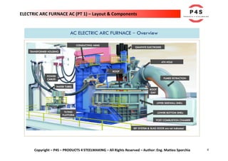
- 3. 3 Copyright – P4S – PRODUCTS 4 STEELMAKING – All Rights Reserved – Author: Eng. Matteo Sporchia ELECTRIC ARC FURNACE AC (PT 1) – Layout & Components INTRODUCTION In this article we're going to make a detailed description of the design features of an AC (alternative current) Electric Arc Furnace (EAF). The layout of an EAF can be divided into the following parts: 1. FURNACE STRUCTURE 2. FURNACE MOVEMENTS 3. PRIMARY ELECTRICAL SYSTEM 4. SECONDARY ELECTRICAL SYSTEM 5. AUXILIARY SYSTEM 6. WATER COOLING SYSTEM
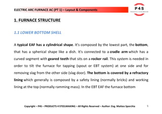
- 5. 5 Copyright – P4S – PRODUCTS 4 STEELMAKING – All Rights Reserved – Author: Eng. Matteo Sporchia ELECTRIC ARC FURNACE AC (PT 1) – Layout & Components 1. FURNACE STRUCTURE 1.1 LOWER BOTTOM SHELL A typical EAF has a cylindrical shape. It's composed by the lowest part, the bottom, that has a spherical shape like a dish. It's connected to a cradle arm which has a curved segment with geared teeth that sits on a rocker rail. This system is needed in order to tilt the furnace for tapping (spout or EBT system) at one side and for removing slag from the other side (slag door). The bottom is covered by a refractory lining which generally is composed by a safety lining (normally bricks) and working lining at the top (normally ramming mass). In the EBT EAF the furnace bottom
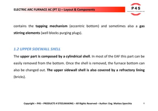
- 6. 6 Copyright – P4S – PRODUCTS 4 STEELMAKING – All Rights Reserved – Author: Eng. Matteo Sporchia ELECTRIC ARC FURNACE AC (PT 1) – Layout & Components contains the tapping mechanism (eccentric bottom) and sometimes also a gas stirring elements (well blocks purging plugs). 1.2 UPPER SIDEWALL SHELL The upper part is composed by a cylindrical shell. In most of the EAF this part can be easily removed from the bottom. Once the shell is removed, the furnace bottom can also be changed out. The upper sidewall shell is also covered by a refractory lining (bricks).
- 8. 8 Copyright – P4S – PRODUCTS 4 STEELMAKING – All Rights Reserved – Author: Eng. Matteo Sporchia ELECTRIC ARC FURNACE AC (PT 1) – Layout & Components 1.4 ROOF The upper part, called roof, of the furnace is a flattened sphere. The roof consists of a water cooled roof ring which forms the outer perimeter. This is a kind of cage where water cooled panels are inserted and form a cylindrical opening at the center. The refractory delta section is inserted to fill this opening. This delta section has minimum opening around the electrodes without risk of arcing between the electrodes and the water cooled panels. Generally, roof and electrode supports can be moved together or independently.
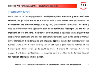
- 9. 9 Copyright – P4S – PRODUCTS 4 STEELMAKING – All Rights Reserved – Author: Eng. Matteo Sporchia ELECTRIC ARC FURNACE AC (PT 1) – Layout & Components 1.5 OPENING AREAS Delta refractory roof is equipped with three opening areas where the graphite electrode columns can go inside the furnace. Another hole (called "fourth hole") is used for the extraction of the furnace fumes (suction system). An additional hole (called "fifth hole") may be provided for other operations such as the continuous feeding of DRI and HBI or injections of coal and lime. The sidewall of the furnace is equipped with a slag door for slag removal operations and also for additional operations such as the using of manual oxygen lances. In the side tapping EAF a tapping spout is installed at the sidewall of the furnace while in the bottom tapping EAF an EBT system (tap hole) is installed at the bottom part. Other several ports could be installed around the furnace shell to be equipped with burners. Opening areas may also be provided low in the furnace sidewall for injection of oxygen, lime or carbon.
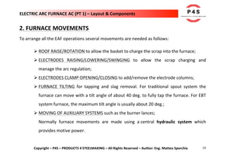
- 10. 10 Copyright – P4S – PRODUCTS 4 STEELMAKING – All Rights Reserved – Author: Eng. Matteo Sporchia ELECTRIC ARC FURNACE AC (PT 1) – Layout & Components 2. FURNACE MOVEMENTS To arrange all the EAF operations several movements are needed as follows: Ø ROOF RAISE/ROTATION to allow the basket to charge the scrap into the furnace; Ø ELECTRODES RAISING/LOWERING/SWINGING to allow the scrap charging and manage the arc regulation; Ø ELECTRODES CLAMP OPENING/CLOSING to add/remove the electrode columns; Ø FURNACE TILTING for tapping and slag removal. For traditional spout system the furnace can move with a tilt angle of about 40 deg. to fully tap the furnace. For EBT system furnace, the maximum tilt angle is usually about 20 deg.; Ø MOVING OF AUXILIARY SYSTEMS such as the burner lances; Normally furnace movements are made using a central hydraulic system which provides motive power.
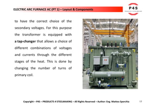
- 11. 11 Copyright – P4S – PRODUCTS 4 STEELMAKING – All Rights Reserved – Author: Eng. Matteo Sporchia ELECTRIC ARC FURNACE AC (PT 1) – Layout & Components 3. PRIMARY ELECTRICAL SYSTEM 3.1 STEP-DOWN TRANSFORMER The EAF electrical system is generally composed by a primary system consisting of a step-down transformer which receives power from the national grid system for feeding the power after stepping down to the EAF transformer. This first transformer steps the voltage down from the high voltage line to a medium voltage level (usually 33 kV).
- 12. 12 Copyright – P4S – PRODUCTS 4 STEELMAKING – All Rights Reserved – Author: Eng. Matteo Sporchia ELECTRIC ARC FURNACE AC (PT 1) – Layout & Components The main breaker at the primary system isolates the electrical systems at the EAF from the grid. On the secondary side of the primary electrical system, a vacuum switch and motorized disconnect switch are usually provided to isolate the secondary furnace transformer from the primary power supply. 3.2 EAF TRANSFORMER A heavy duty EAF transformer receives the primary low current, high voltage power and transforms this to a high current, low voltage power to be used in the EAF. The mentioned transformer is designed in order to allow operation of the arcs at the desired range of arc voltages and currents. During EAF operation, there are varying needs of arc voltage/current configuration through and for this reason it's necessary
- 13. 13 Copyright – P4S – PRODUCTS 4 STEELMAKING – All Rights Reserved – Author: Eng. Matteo Sporchia ELECTRIC ARC FURNACE AC (PT 1) – Layout & Components to have the correct choice of the secondary voltages. For this purpose the transformer is equipped with a tap-changer that allows a choice of different combinations of voltages and currents through the different stages of the heat. This is done by changing the number of turns of primary coil.
- 15. 15 Copyright – P4S – PRODUCTS 4 STEELMAKING – All Rights Reserved – Author: Eng. Matteo Sporchia ELECTRIC ARC FURNACE AC (PT 1) – Layout & Components 4.2 FLEXIBLE POWER CABLES The flexible cables are generally water cooled cables, generally made by copper ropes (parallel connected). They're used to establish electrical continuity between fixed blocks and electrodes holding arms. These cables must be flexible to permit movement of the electrode arms up and down and to allow swinging the electrode arms and roof when charging of the furnace
- 16. 16 Copyright – P4S – PRODUCTS 4 STEELMAKING – All Rights Reserved – Author: Eng. Matteo Sporchia ELECTRIC ARC FURNACE AC (PT 1) – Layout & Components 4.3 CURRENT CONDUCTING ARM / BUS TUBES Bus tubes provide the electrical connection between the power cables and the electrode holder (contact pads) and usually consists of water cooled copper or aluminum pipes, placed on the electrodes supporting arms. Many modern furnaces utilize current conducting arms in which the arm itself transmits electricity to the electrode holder and contact pad. Current conducting arms are usually fabricated from copper clad steel or aluminum alloys.
- 18. 18 Copyright – P4S – PRODUCTS 4 STEELMAKING – All Rights Reserved – Author: Eng. Matteo Sporchia ELECTRIC ARC FURNACE AC (PT 1) – Layout & Components 4.5 GRAPHITE ELECTRODES The graphite electrodes deliver power to furnace in the form of an electric arc between the electrode and the furnace charge. The arc itself is a plasma of hot, ionic gasses with temperature about 3000 °C. The electrode/arm/mast/cable assembly is quite heavy and is moved vertically for control purposes generally by a hydraulic cylinder incorporated in the mast.
- 19. 19 Copyright – P4S – PRODUCTS 4 STEELMAKING – All Rights Reserved – Author: Eng. Matteo Sporchia ELECTRIC ARC FURNACE AC (PT 1) – Layout & Components Since the arc length is dependent, amongst other things, on the ever changing level of scrap or liquid under the electrode, it is necessary to have an automatic control over electrode position known as the regulation system. 5. AUXILIARY SYSTEM There're different auxiliary systems that are adopted to guarantee the operations and performance of the EAF. Here below are described the most common auxiliary systems:
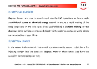
- 20. 20 Copyright – P4S – PRODUCTS 4 STEELMAKING – All Rights Reserved – Author: Eng. Matteo Sporchia ELECTRIC ARC FURNACE AC (PT 1) – Layout & Components 5.1 OXY-FUEL BURNERS Oxy-fuel burners are now commonly used into the EAF operations as they provide an additional source of chemical energy needed to ensure a rapid melting of the scrap (especially in the cold spot areas) guaranteeing a uniform melting of the charging. Some burners are mounted directly in the water cooled panel while others are mounted in a copper block. 5.2 OXYGEN LANCES In the recent EAFs automatic lances and non consumable, water cooled lance for injecting oxygen into the steel are adopted. Many of these lances also have the capability to inject carbon as well.
- 24. 24 Copyright – P4S – PRODUCTS 4 STEELMAKING – All Rights Reserved – Author: Eng. Matteo Sporchia ELECTRIC ARC FURNACE AC (PT 1) – Layout & Components 5.6 TEMPERSTURE SAMPLING A simple thermocouple is used for temperature tracking throughout the heat. Expendable probes are also used for tracking bath carbon content and dissolved oxygen levels in the steel. 6. WATER COOLING SYSTEM The water cooling system is an essential part in the EAF structure. There are different cooling systems such as transformer cooling, delta closure cooling, bus tube cooling and electrode holder cooling. These systems usually consist of a closed loop circuit, which conducts water through these sensitive pieces of equipment. The water in the
- 25. 25 Copyright – P4S – PRODUCTS 4 STEELMAKING – All Rights Reserved – Author: Eng. Matteo Sporchia ELECTRIC ARC FURNACE AC (PT 1) – Layout & Components closed loop circuit passes through a heat exchanger to remove heat. There are other water cooled systems, such as furnace side panels, roof panels, off gas system and so on. Sensitive pieces of equipment normally have instrumentation installed for measuring and monitoring the cooling water flow rate and temperature. #P4S #products4steelmaking #steel #steelmaking #technology #engineering #metallurgy #industrialengineering #furnace