Location via proxy:   [ UP ]  
[Report a bug]   [Manage cookies]                
SlideShare a Scribd company logo

1

Faculty of Engineering Petroleum
Engineering Department
Mechanics of Material Lab.
Exp. (Sample Preparation)
Prepared by: Ahmad Jalal Hasan
Muhammad Fuad Rashid
Muhammad Hasan Aziz
Supervised by: Dr. Dyar
Date of Submit: 01/10/2019

2

2
Table of Contents
1.1. Aim.......................................................................................................................................................... 3
1.2. Introduction............................................................................................................................................ 3
1.3. tensile test experiment............................................................................................................................ 3
1.4. Sample Preparation................................................................................................................................ 4
1.5. Tensile Specimens and Testing Machines.............................................................................................. 5
1.6. discussion................................................................................................................................................ 7
1.7. Conclusion .............................................................................................................................................. 8
1.8. References............................................................................................................................................... 8

3

3
1.1. Aim
This International Standard specifies the method for tensile testing of metallic
materials and defines the mechanical properties which can be determined at ambient
temperature.
1.2. Introduction
ASTM's physical and mechanical testing standards provide guides for the proper
procedures employed in the determination of the physical, mechanical, and
metallographic properties of certain materials, particularly metals and alloys. Using
test methods such as scanning electron microscopy, hole-drilling strain-gage
method, semiautomatic and automatic image analysis, and X-ray diffraction,
parameters like elastic moduli, impact strength, ductility, hardness, residual stress,
and grain size are measured. These physical and mechanical testing standards allow
metallurgical laboratories, manufacturers, and other producers and users of metals
and alloys to examine and evaluate such materials for strength and quality to ensure
safety towards their end-use.
The mechanical properties of materials are determined by performing carefully
designed laboratory experiments that replicate as nearly as possible the service
conditions. In the real life, there are many factors involved in the nature in which
loads are applied on a material. The following are some common examples of how
these loads might be applied: tensile, compressive and shear, just to name a few.
These properties are important in materials selections for mechanical design.
Other factors that often complicate the design process include temperature and
time factors.
1.3. tensile test experiment
The topic of this lab is confined to the tensile property of polymers. Figure 6.1
shows a tensile testing machine, which looks similar to the one used in this lab. This
test is a destructive method, in which a specimen of a standard shape and dimensions
(prepared according to ASTM D 638: standard test method for tensile properties of
plastics) is subjected to an axial load. As shown in Figure 6.1, during a typical

4

4
tensile experiment, a dog-bone shaped specimen is gripped at
its two ends and is pulled to elongate at a determined rate
to its breakpoint; a highly ductile polymer may not reach its
breakpoint. The tensile tester used in this lab is
manufactured by Shimadzu Corporations (model AJS-
It has a maximum load of 100 kN and a variable
pulling rate. The setup of the experiment could be
changed to accommodate different types of mechanical
testing, according to the ASTM standard (e.g.
compression test, etc).
1.4. Sample Preparation
 The polymer specimens are dog-bone shaped. They were injection molded, and
its dimensions were determined according to the ASTMD 638, mentioned
earlier in the introduction.
 Measure the thickness, width and gage length of polymer samples using a pair
Vernier calipers. These dimensions should be approximately the same for each
sample.
Figure 1 A photograph of a tensile
machine (Shimadzu, Autograph AG-
10TC).

5

5
1.5. Tensile Specimens and Testing Machines
Tensile Specimens. Consider the typical tensile specimen shown in Fig. 2. It has
enlarged ends or shoulders for
gripping. The important part of the specimen is the gage section. The cross-sectional
area of the gage section is reduced relative to that of the remainder of the specimen so
that deformation and failure will be
localized
Figure 2 Typical tensile specimen, showing a reduced gage section and enlarged shoulders. To avoid end effects from the shoulders, the length of the
transition region should be at least as great as the diameter, and the total length of the reduced section

6

6
in this region. The gage length is the region over which measurements are made and
is centered within the reduced section. The distances between the ends of the gage
section and the shoulders should be great enough so that the larger ends do not
constrain deformation within the gage section, and the gage length should be great
relative to its diameter. Otherwise, the stress state will be more complex than simple
tension. There are various ways of gripping the specimen. The end may be screwed
into a threaded grip, or it may be pinned; butt ends may be used, or the grip section
may be held between wedges. There are still other methods. The most important
concern in the selection of a gripping method is to ensure that the specimen can be
held at the maximum load without slippage or failure in the grip section. Bending
should be minimized.
Testing Machines. The most common testing machines are universal testers. terials in
tension, compression, or bending. Their primary function is to create the stress-
strain curve described in the following section in this chapter.
Testing machines are either electromechanical or hydraulic. The principal difference
is the method by which the load is applied.
Electromechanical machines are based on a variable-speed electric motor; a gear
reduction system; and one, two, or four screws that move the crosshead up or down.
This motion loads the specimen in tension or compression. Crosshead speeds can be
changed by changing the speed of the motor. A microprocessor-based closed-loop
servo system can be implemented to accurately control the speed of the crosshead.
Hydraulic testing machines are based on either a single or dual-acting piston that
moves the crosshead up or down. However, most static hydraulic testing machines
have a single acting piston or ram. In a manually operated machine, the operator
adjusts the orifice of a pressure-compensated needle valve to control the rate of
loading. In a closed-loop hydraulic servo
system, the needle valve is
replaced by an electrically
operated servo valve for
precise control.

7

7
0
Figure 3 Systems for gripping tensile specimens. For round specimens, these include threaded grips (a), serrated
wedges (b), and, for butt end specimens, split collars constrained by a solid collar (c). Sheet specimens may be gripped
with pins (d) or serr
1.6. discussion
the dimension for a lab testing exactly for this experiment should
match the standard to test a materials properties according to
ASTM (American standard testing materials ) that means the
sample should have a specification of some properties for example
length and height and thickness and dimeter also the sample must a
homogeneous sample and so on , also by observing the
experiments test for example test it noted that was a successful
experiment and dissipating from bias and errors to the graphs and
test results, this due to the sample had a uniforming of properties
as mentioned high above.

8

8
1.7. Conclusion
Finally, I would say the process of preparing a sample for
specimen’s physical properties should be done carefully and
preparing its dimensions due to standards precisely to get the right
values for their properties in graph results.
1.8. References
 Matweb.com. (2015). MatWeb - The Online Materials
Information Resource.
 ASTM Standard C33, 2003
 National Council on Radiation Protection and Measurements
(NCRP)
 American Society of Testing and Materials (ASTM)
 Radiological and Environmental Sciences Laboratory
(RESL), Idaho Falls, Idaho
(Operated by the DOE)
 DOE Technical Measurements Center, Grand Junction, CO
 Environmental Measurements Laboratory (EML); formerly
the Health and Safety
Laboratory of the DOE

More Related Content

exp: sample preparation for tensile test

  • 1. Faculty of Engineering Petroleum Engineering Department Mechanics of Material Lab. Exp. (Sample Preparation) Prepared by: Ahmad Jalal Hasan Muhammad Fuad Rashid Muhammad Hasan Aziz Supervised by: Dr. Dyar Date of Submit: 01/10/2019
  • 2. 2 Table of Contents 1.1. Aim.......................................................................................................................................................... 3 1.2. Introduction............................................................................................................................................ 3 1.3. tensile test experiment............................................................................................................................ 3 1.4. Sample Preparation................................................................................................................................ 4 1.5. Tensile Specimens and Testing Machines.............................................................................................. 5 1.6. discussion................................................................................................................................................ 7 1.7. Conclusion .............................................................................................................................................. 8 1.8. References............................................................................................................................................... 8
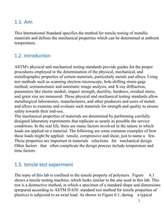
  • 3. 3 1.1. Aim This International Standard specifies the method for tensile testing of metallic materials and defines the mechanical properties which can be determined at ambient temperature. 1.2. Introduction ASTM's physical and mechanical testing standards provide guides for the proper procedures employed in the determination of the physical, mechanical, and metallographic properties of certain materials, particularly metals and alloys. Using test methods such as scanning electron microscopy, hole-drilling strain-gage method, semiautomatic and automatic image analysis, and X-ray diffraction, parameters like elastic moduli, impact strength, ductility, hardness, residual stress, and grain size are measured. These physical and mechanical testing standards allow metallurgical laboratories, manufacturers, and other producers and users of metals and alloys to examine and evaluate such materials for strength and quality to ensure safety towards their end-use. The mechanical properties of materials are determined by performing carefully designed laboratory experiments that replicate as nearly as possible the service conditions. In the real life, there are many factors involved in the nature in which loads are applied on a material. The following are some common examples of how these loads might be applied: tensile, compressive and shear, just to name a few. These properties are important in materials selections for mechanical design. Other factors that often complicate the design process include temperature and time factors. 1.3. tensile test experiment The topic of this lab is confined to the tensile property of polymers. Figure 6.1 shows a tensile testing machine, which looks similar to the one used in this lab. This test is a destructive method, in which a specimen of a standard shape and dimensions (prepared according to ASTM D 638: standard test method for tensile properties of plastics) is subjected to an axial load. As shown in Figure 6.1, during a typical
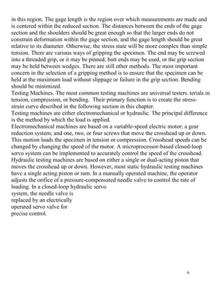
  • 4. 4 tensile experiment, a dog-bone shaped specimen is gripped at its two ends and is pulled to elongate at a determined rate to its breakpoint; a highly ductile polymer may not reach its breakpoint. The tensile tester used in this lab is manufactured by Shimadzu Corporations (model AJS- It has a maximum load of 100 kN and a variable pulling rate. The setup of the experiment could be changed to accommodate different types of mechanical testing, according to the ASTM standard (e.g. compression test, etc). 1.4. Sample Preparation  The polymer specimens are dog-bone shaped. They were injection molded, and its dimensions were determined according to the ASTMD 638, mentioned earlier in the introduction.  Measure the thickness, width and gage length of polymer samples using a pair Vernier calipers. These dimensions should be approximately the same for each sample. Figure 1 A photograph of a tensile machine (Shimadzu, Autograph AG- 10TC).
  • 5. 5 1.5. Tensile Specimens and Testing Machines Tensile Specimens. Consider the typical tensile specimen shown in Fig. 2. It has enlarged ends or shoulders for gripping. The important part of the specimen is the gage section. The cross-sectional area of the gage section is reduced relative to that of the remainder of the specimen so that deformation and failure will be localized Figure 2 Typical tensile specimen, showing a reduced gage section and enlarged shoulders. To avoid end effects from the shoulders, the length of the transition region should be at least as great as the diameter, and the total length of the reduced section
  • 6. 6 in this region. The gage length is the region over which measurements are made and is centered within the reduced section. The distances between the ends of the gage section and the shoulders should be great enough so that the larger ends do not constrain deformation within the gage section, and the gage length should be great relative to its diameter. Otherwise, the stress state will be more complex than simple tension. There are various ways of gripping the specimen. The end may be screwed into a threaded grip, or it may be pinned; butt ends may be used, or the grip section may be held between wedges. There are still other methods. The most important concern in the selection of a gripping method is to ensure that the specimen can be held at the maximum load without slippage or failure in the grip section. Bending should be minimized. Testing Machines. The most common testing machines are universal testers. terials in tension, compression, or bending. Their primary function is to create the stress- strain curve described in the following section in this chapter. Testing machines are either electromechanical or hydraulic. The principal difference is the method by which the load is applied. Electromechanical machines are based on a variable-speed electric motor; a gear reduction system; and one, two, or four screws that move the crosshead up or down. This motion loads the specimen in tension or compression. Crosshead speeds can be changed by changing the speed of the motor. A microprocessor-based closed-loop servo system can be implemented to accurately control the speed of the crosshead. Hydraulic testing machines are based on either a single or dual-acting piston that moves the crosshead up or down. However, most static hydraulic testing machines have a single acting piston or ram. In a manually operated machine, the operator adjusts the orifice of a pressure-compensated needle valve to control the rate of loading. In a closed-loop hydraulic servo system, the needle valve is replaced by an electrically operated servo valve for precise control.
  • 7. 7 0 Figure 3 Systems for gripping tensile specimens. For round specimens, these include threaded grips (a), serrated wedges (b), and, for butt end specimens, split collars constrained by a solid collar (c). Sheet specimens may be gripped with pins (d) or serr 1.6. discussion the dimension for a lab testing exactly for this experiment should match the standard to test a materials properties according to ASTM (American standard testing materials ) that means the sample should have a specification of some properties for example length and height and thickness and dimeter also the sample must a homogeneous sample and so on , also by observing the experiments test for example test it noted that was a successful experiment and dissipating from bias and errors to the graphs and test results, this due to the sample had a uniforming of properties as mentioned high above.
  • 8. 8 1.7. Conclusion Finally, I would say the process of preparing a sample for specimen’s physical properties should be done carefully and preparing its dimensions due to standards precisely to get the right values for their properties in graph results. 1.8. References  Matweb.com. (2015). MatWeb - The Online Materials Information Resource.  ASTM Standard C33, 2003  National Council on Radiation Protection and Measurements (NCRP)  American Society of Testing and Materials (ASTM)  Radiological and Environmental Sciences Laboratory (RESL), Idaho Falls, Idaho (Operated by the DOE)  DOE Technical Measurements Center, Grand Junction, CO  Environmental Measurements Laboratory (EML); formerly the Health and Safety Laboratory of the DOE