Facts devices
•Download as PPTX, PDF•
9 likes•13,950 views

The concept of FACTS (Flexible Alternating Current Transmission System) refers to a family of power electronics-based devices able to enhance AC system controllability and stability and to increase power transfer capability.
Report
Share
Related slideshows


Facts devices
- 1. A Seminar Presentation on FACTS DEVICES By Vinod Srivastava Department of Electrical Engineering IFTM University, Moradabad
- 2. CONTENTS Introduction Benefits of FACTS FACTS Controllers Shunt Series Hybrid Conclusion References
- 3. Introduction • The concept of FACTS (Flexible Alternating Current Transmission System) refers to a family of power electronics- based devices able to enhance AC system controllability and stability and to increase power transfer capability. • The design of the different schemes and configurations of FACTS devices is based on the combination of traditional power system components (such as transformers, reactors, switches, and capacitors) with power electronics elements (such as various types of transistors and thyristors)
- 4. Benefits of FACTS • To increase the power transfer capability of transmission networks. • To provide direct control of power flow over designated transmission routes. • Control of power flow as ordered so that it follows on the prescribed transmission corridors. • Increase the loading capability of lines to their thermal capabilities
- 5. FACTS CONTROLLERS SHUNT • Static Var Compensator • Static Synchronous Compensator • STATCOM SERIES • Thyristor Controlled Series Compensator (TCSC) • Static Synchronous Series Compensator • Fault Current Limiter (SC+FPD) HYBRID • Dynamic Power Flow Controller (DFC) • HVDC Light/HVDCLightB2B/UPFC
- 6. Shunt Connected Controllers • In shunt compensation, power system is connected in shunt (parallel) with the FACTS. It works as a controllable current source. Shunt compensation is of two types: • Shunt capacitive compensation This method is used to improve the power factor. Whenever an inductive load is connected to the transmission line, power factor lags because of lagging load current. To compensate, a shunt capacitor is connected which draws current leading the source voltage. The net result is improvement in power factor.
- 7. Contd…. • Shunt inductive compensation: This method is used either when charging the transmission line, or, when there is very low load at the receiving end. Due to very low, or no load – very low current flows through the transmission line. Shunt capacitance in the transmission line causes voltage amplification (Ferranti effect). The receiving end voltage may become double the sending end voltage (generally in case of very long transmission lines). To compensate, shunt inductors are connected across the transmission line.
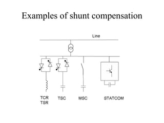
- 8. Examples of shunt compensation
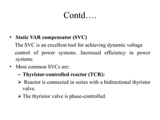
- 9. Contd…. • Static VAR compensator (SVC) The SVC is an excellent tool for achieving dynamic voltage control of power systems. Increased efficiency in power systems • Most common SVCs are: – Thyristor-controlled reactor (TCR): Reactor is connected in series with a bidirectional thyristor valve. The thyristor valve is phase-controlled.
- 10. Contd…. – Thyristor-switched reactor (TSR): Same as TCR but thyristor is either in zero- or full- conduction. Equivalent reactance is varied in stepwise manner. – Thyristor-switched capacitor (TSC): capacitor is connected in series with a bidirectional thyristor valve. Thyristor is either in zero- or full- conduction. Equivalent reactance is varied in stepwise manner.
- 11. Contd…. – Mechanically-switched capacitor (MSC): Capacitor is switched by circuit-breaker. It aims at compensating steady state reactive power. It is switched only a few times a day.
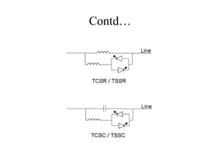
- 12. Series Connected Controller FACTS for series compensation modify line impedance. Examples: Thyristor-controlled series capacitor (TCSC): a series capacitor bank is shunted by a thyristor- controlled reactor Thyristor-controlled series reactor (TCSR): a series reactor bank is shunted by a thyristor-controlled reactor Thyristor-switched series capacitor (TSSC): a series capacitor bank is shunted by a thyristor-switched reactor Thyristor-switched series reactor (TSSR): a series reactor bank is shunted by a thyristor-switched reactor.
- 13. Contd…
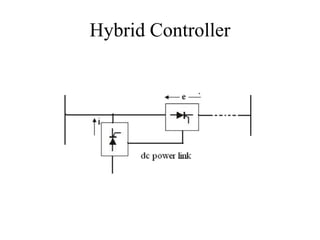
- 15. Contd…. It could be a combination of separate series & shunt controllers or unified power flow controller. Inject current into the system with the shunt controller and voltage in series with the line with series controller. When the controllers are unified, exchange real power between series and shunt controllers via power link.
- 16. Conclusion The above discussion reflects various work and philophies are covered in the area of FACTS. The potential role that FACT may play towards the development of the future Indian transmission system. In fact, FACT elements may provide Indian TSOs with effective solutions to the several criticalities they encounter. Finally, it has to be noted that in a highly meshed network, as the Indian FACTS become extensively deployed, they will deliver real benefits only when subjected to a coordinated and hierarchical control.
- 17. References https://en.wikipedia.org/wiki/Flexible_AC_transmission_syste m#/media/File:FACTS_series_compensation1.PNG https://www.slideshare.net/ayyarao/basic-types-of-facts- controllers https://www.slideshare.net/Hamayun14373Liaqat/facts- devices-power-electronics?qid=fd59c500-4423-4a15-8857- e24079872d84&v=&b=&from_search=3
- 18. THANK YOU