


FEEMSSD presentation on shell and tube heat exchanger75 .pptx
- 1. Design of Shell and Tube Heat Exchanger Presented by: Aman Yadav Department of Chemical Engineering M.M.M.U.T, Gorakhpur Madan Mohan Malviya University of Technology Gorakhpur (UP State Govt. University) Authors: Mr. Sarvesh Patel Mr. Maharshi Yadav Prof. Vitthal L. Gole Dr. Jyoti Sharma
- 2. Content Introduction Shell and Tube Heat Exchanger Component of Shell and tube Heat Exchanger Types of Baffles Types of Shell and Tube Heat Exchanger Objective Selection of Fluids For Tube and Shell Sides Thermal Design Considerations Initial Condition for the Design Shell and tube heat exchanger Efficiency of an Exchanger Process (Thermal Design Procedure) Results and Discussions and futuristic scope
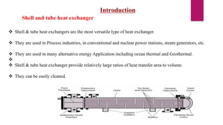
- 3. Introduction Shell & tube heat exchangers are the most versatile type of heat exchanger. They are used in Process industries, in conventional and nuclear power stations, steam generators, etc. They are used in many alternative energy Application including ocean thermal and Geothermal. Shell & tube heat exchanger provide relatively large ratios of heat transfer area to volume. They can be easily cleaned. Shell and tube heat exchanger
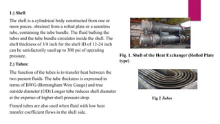
- 4. 1.) Shell The shell is a cylindrical body constructed from one or more pieces, obtained from a rolled plate or a seamless tube, containing the tube bundle. The fluid bathing the tubes and the tube bundle circulates inside the shell. The shell thickness of 3/8 inch for the shell ID of 12-24 inch can be satisfactorily used up to 300 psi of operating pressure. 2.) Tubes: The function of the tubes is to transfer heat between the two present fluids. The tube thickness is expressed in terms of BWG (Birmingham Wire Gauge) and true outside diameter (OD) Longer tube reduces shell diameter at the expense of higher shell pressure drop. Finned tubes are also used when fluid with low heat transfer coefficient flows in the shell side. Fig. 1. Shell of the Heat Exchanger (Rolled Plate type) Fig 2 Tubes
- 5. 3.)Tube bundle: The tube bundle is a component formed mainly by tubes and baffles. 4.)Tubesheet: The tube bundle ends in circular perforated plates called Tubesheets Fig 3 Tubebundles Fig 4 Tubesheets and Expansion joints
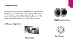
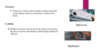
- 6. 5.)Expansion joint: Fig 5 Expansion Joints The expansion joint prevents the problem of thermal stress which may occur when there is a substantial difference of expansion between the shell and the tubes because of the temperature difference between the two fluid streams. 6.)Flanges and gaskets: Fig 6 Flanges Fig 7 Gaskets
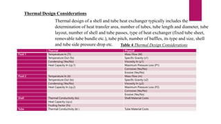
- 7. 8.)Nozzles: Nozzles are small sections of pipes welded to the shell or the channel which act as the inlet or outlet of the fluids. Fig 9 Nozzles 9.) Baffles Baffles are used to increase the fluid velocity by diverting the flow across the tube bundle to obtain higher transfer co- efficient. Fig 10 Baffles
- 8. Objective: To study the design of Shell and Tube Heat Exchanger for an Industry. Selection of fluids for tube and the shell side The routing of the shell side and tube side fluids has considerable effects on the heat exchanger design. Some general guidelines for positioning the fluids are given in Table Table 3 Specifications of Fluids Tube side fluid Shell side fluid Corrosive fluid Cooling water Fouling fluid Less viscous fluid High pressure steams hotter fluid Condensing vapour (Unless corrosive) Fluid with large temperature difference(>40C)
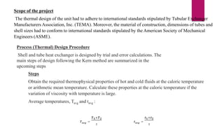
- 9. Thermal Design Considerations Thermal design of a shell and tube heat exchanger typically includes the determination of heat transfer area, number of tubes, tube length and diameter, tube layout, number of shell and tube passes, type of heat exchanger (fixed tube sheet, removable tube bundle etc.), tube pitch, number of baffles, its type and size, shell and tube side pressure drop etc. Table 4 Thermal Design Considerations Thermal Physical Fluid 1 Temperature In (Ti) Mass Flow (M) Temperature Out (To) Specific Gravity (s1) Condensing (Yes/No) Viscosity In (µ1) Heat Capacity In (cp,1) Maximum Pressure Loss (P1) Corrosive (Yes/No) Erosive (Yes/No) Fluid 2 Temperature In (ti) Mass Flow (m) Temperature Out (to) Specific Gravity (s2) Condensing (Yes/No) Viscosity In (µ2) Heat Capacity In (cp,2) Maximum Pressure Loss (P2) Corrosive (Yes/No) Erosive (Yes/No) Shell Thermal Conductivity (ks) Shell Material Costs Heat Capacity (cp,s) Fouling Factor (Fs) Tube Thermal Conductivity (kt ) Tube Material Costs
- 10. Report Objectives 1.) Produce detailed thermal design specifications of heat exchanger E-607 based on a cumene production plant. 2.) Specification of the unit using TEMA codes (i.e. BEM, AEM, NEN) 3.)A clear and concise justification of fluid allocation within the unit. 4.) Selection of material for construction and dimensions of the unit including but not limited to the tube length, shell and tube diameters. 5.) Presentation of the Process and instrumentation diagram (PID) and a detailed cross sectional drawing of the unit. 6.) Rigorous cost estimations for the initial fabrication of the unit. Project statement In this present work, the design of a shell and tube heat exchanger unit was carried out using design specifications. The task at hand was to design a shell and tube heat exchanger to cool a Kerosene- Crude Oil mixture rich in cumene emerging as a distillate product from a distillation unit. The heat exchanger was based on a Crude Distillation plant. The specifications of heat exchanger unit were 1-shell, 1-tube pass with fixed tube sheets on the front and rear end. The flow pattern was also specified to be countercurrent flow, and Crude Oil was the proposed cooling fluid. However, due to high pressure drops experienced on the shell and tube side.
- 11. Scope of the project The thermal design of the unit had to adhere to international standards stipulated by Tubular Exchanger Manufacturers Association, Inc. (TEMA). Moreover, the material of construction, dimensions of tubes and shell sizes had to conform to international standards stipulated by the American Society of Mechanical Engineers (ASME). Process (Thermal) Design Procedure Shell and tube heat exchanger is designed by trial and error calculations. The main steps of design following the Kern method are summarized in the upcoming steps Steps Obtain the required thermophysical properties of hot and cold fluids at the caloric temperature or arithmetic mean temperature. Calculate these properties at the caloric temperature if the variation of viscosity with temperature is large. Average temperatures, Tavg and tavg : 𝑻𝒂𝒗𝒈 = 𝑻𝟏+𝑻𝟐 𝟐 𝒕𝒂𝒗𝒈 = 𝒕𝟏+𝒕𝟐 𝟐
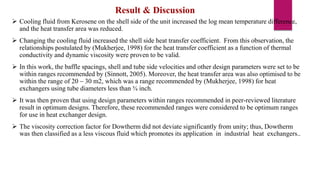
- 12. Result & Discussion Cooling fluid from Kerosene on the shell side of the unit increased the log mean temperature difference, and the heat transfer area was reduced. Changing the cooling fluid increased the shell side heat transfer coefficient. From this observation, the relationships postulated by (Mukherjee, 1998) for the heat transfer coefficient as a function of thermal conductivity and dynamic viscosity were proven to be valid. In this work, the baffle spacings, shell and tube side velocities and other design parameters were set to be within ranges recommended by (Sinnott, 2005). Moreover, the heat transfer area was also optimised to be within the range of 20 – 30 m2, which was a range recommended by (Mukherjee, 1998) for heat exchangers using tube diameters less than ¾ inch. It was then proven that using design parameters within ranges recommended in peer-reviewed literature result in optimum designs. Therefore, these recommended ranges were considered to be optimum ranges for use in heat exchanger design. The viscosity correction factor for Dowtherm did not deviate significantly from unity; thus, Dowtherm was then classified as a less viscous fluid which promotes its application in industrial heat exchangers..
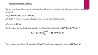
- 13. Observations and Costing We have performed an example on basis of which we have obtained the following inference has been obtained ∆Ps = 39.4503 psi, ∆Pt = 1.044 psi, ∆Ps &∆Pt < 10 psi is considered as allowable pressure drop for tube side. ∆Ps(corrected)=10 psi It will reduce the shell side heat-transfer coefficient by a factor of (1/2)0.8(h0∝ Re 0.8 ∝ us 0.8) 𝒉𝟎 = 𝟐𝟕𝟒𝟎 × 𝟏 𝟐 𝟎.𝟖 = 𝟏𝟓𝟕𝟑 W/m2 0C This gives an overall coefficient of 615W/m2 0C- still above assumed value of 600 W/m2 0C
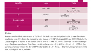
- 14. Variable Value Units ho =482.865 𝐵𝑡𝑢 ℎ𝑟 ⋅ 𝑓𝑡2.0 𝐹 ∕ 𝑓𝑡 hi =678.37 . 𝐵𝑡𝑢 ℎ𝑟⋅𝑓𝑡2.0𝐹∕𝑓𝑡 ho(corrected) =277 𝐵𝑡𝑢 ℎ𝑟 ⋅ 𝑓𝑡2.0 𝐹 ∕ 𝑓𝑡 Uo =130 𝐵𝑡𝑢 ℎ𝑟 ⋅ 𝑓𝑡2.0 𝐹 Costing For the calculated heat transfer area of 28.51 m2, the basic cost was interpolated to be $18000 for carbon steel in the year 2004. From the cumulative price change of 35.92 % between 2004 and 2020 (Alloth, L. C., 2013), the price of the unit in this current year of 2020 is $18000 × 1.359 = $ 24465.56 The heat exchanger was a fixed tube sheet hence: Type factor = 0.8 𝑃𝑢𝑟𝑐h𝑎𝑠𝑒 𝑐𝑜𝑠𝑡 = $ 24 465.56 × 0.8 × 1 = $ 19,572.48 The currency exchange rate on this day of 15 October 2020 is $ 1.0 = Rs 73.11 Therefore, the current cost of the heat exchanger is Rs 14,30,944.01
- 15. References Coulson and Richardson’s Chemical Engineering: Volume 6: Fluid Flow: Fundamentals and Applications: Chapter 12 Heat Transfer Equipments. Timothy John Rennie, 2004, Numerical and Experimental Studies of a Shell and tube Heat Exchanger, Dept. of Bio-resource Engg. McGill University, Montreal Rajput R.K., 2011. Lancaster, J. . F., 1983. Heat Exchanger Design Handbook. New York: Hemisphere Publishing Corporation. Lavine, A. S., Incropera, F. P., Bergman, T. L. & Dewitt, D., 2011. Fundamentals of HEAT and MASS Transfer. 7th ed. Hoboken: John Wiley & Sons. Inc. Mukherjee, R., 1998. Effectively design shell-and-tube heat exchangers. Chemical Engineering Progress, 94(2). Serth, R. W., 2007. Process heat transfer principles and application. s.l.:Elsevier Science & Technology Books. Sinnott, R. K., 2005. Chemical engineering design. 4th ed. s.l.:Elsevier Butterworth Heinemann.
- 16. Thank You