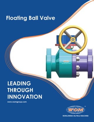
Floating Ball Valve, Floating Ball Valve Surface Equipment - WOM Group
- 3. Floating Ball Valve............................................................................................................................................4 Features and Benefits.......................................................................................................................................5-6 General Design Standards..............................................................................................................................7 Exploded View..................................................................................................................................................8 Class and Dimensional Data...........................................................................................................................9 Operating Options............................................................................................................................................10 Quality Policy....................................................................................................................................................11
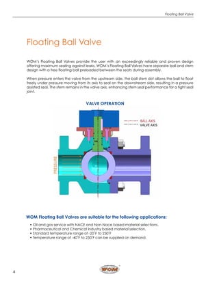
- 4. 4 Floating Ball Valve WOM’s Floating Ball Valves provide the user with an exceedingly reliable and proven design offering maximum sealing against leaks. WOM’s Floating Ball Valves have separate ball and stem design with a free floating ball preloaded between the seats during assembly. When pressure enters the valve from the upstream side, the ball stem slot allows the ball to float freely under pressure moving from its axis to seal on the downstream side, resulting in a pressure assisted seal. The stem remains in the valve axis, enhancing stem seal performance for a tight seal joint. Floating Ball Valve WOM Floating Ball Valves are suitable for the following applications: • Oil and gas service with NACE and Non-Nace based material selections. • Pharmaceutical and Chemical Industry based material selection. • Standard temperature range of -20˚F to 250˚F • Temperature range of -40˚F to 250˚F can be supplied on demand. 4 Floating Ball Valve WOM’s Floating Ball Valves provide the user with an exceedingly reliable and proven design offering maximum sealing against leaks. WOM’s Floating Ball Valves have separate ball and stem design with a free floating ball preloaded between the seats during assembly. When pressure enters the valve from the upstream side, the ball stem slot allows the ball to float freely under pressure moving from its axis to seal on the downstream side, resulting in a pressure assisted seal. The stem remains in the valve axis, enhancing stem seal performance for a tight seal joint. WOM Floating Ball Valves are suitable for the following applications: • Oil and gas service with NACE and Non-Nace based material selections. • Pharmaceutical and Chemical Industry based material selection. • Standard temperature range of -20˚F to 250˚F • Temperature range of -40˚F to 250˚F can be supplied on demand. VALVE OPERATION
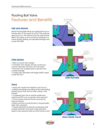
- 5. 5 Worldwide Oilfield Machine Floating Ball Valve Features and Benefits FIRE SAFE DESIGN WOM Floating Ball Valves are designed to be in- line fire safe. In the event of a fire, if the polymer seats burn out, the ball touches the seat pocket fillet in the body or end connector leading to a metal seated sealing. Acceptable leakage rate as per ISO 5208. STEM DESIGN • Blow out proof stem design • Antistatic stem design ensures continuous contact between the stem and the body • The stem has multiple seals to prevent any outside leakage • Larger stem diameter with larger MAST values as per ISO 5211 SEALS • Seats are made from Nylatron and have a multiple seal design providing enhanced sealing performance than that of other valves in the market • A tapered stem thrust washer made from reinforced PTFE acts as primary stem seal joint • Thrust washer reduces friction and hence reduces torque • Body and end connector joint o-ring provides tight static seal joint • Closed diametrical clearance between ball outside diameter and body inside diameter leads to less pressure build up within body cavity 5 Floating Ball Valve Features and Benefits Model 30 & 40 Features and Benefits Fire Safe Design WOM Floating Ball Valves are designed to be in-line fire safe. In the event of a fire, if the polymer seats burn out, the ball touches the seat pocket fillet in the body or end connector leading to a metal seated sealing. Acceptable leakage rate as per ISO 5208. Metal Sealing In case of Fire STEM DESIGN • Blow out proof stem design • Antistatic stem design ensures continuous contact between the stem and the body • The stem has multiple seals to prevent any outside leakage • Larger stem diameter with larger MAST values as per ISO 5211 STEM FEATURESSEALS • Seats are made from Nylatron and have a multi- ple seal design providing enhanced sealing perfor- mance than that of other valves in the market • A tapered stem thrust washer made from reinforced PTFE acts as primary stem seal joint • Thrust washer reduces friction and hence reduces torque • Body and end connector joint o-ring provides tight static seal joint • Closed diametrical clearance between ball outside diameter and body inside diameter leads to less pressure build up within body cavity SEALS INSIDE VALVE Stem Thrust Washer Seat Stem Seals O-Rings O-Rings Seat Anti Static Design Blow Out Proof Stem in Body ISO 5211 Mounting
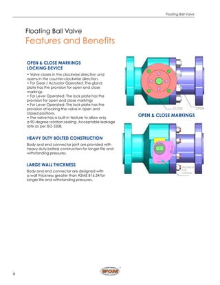
- 6. 6 Floating Ball Valve Floating Ball Valve Features and Benefits OPEN & CLOSE MARKINGS LOCKING DEVICE • Valve closes in the clockwise direction and opens in the counter-clockwise direction. • For Gear / Actuator Operated: The gland plate has the provision for open and close markings • For Lever Operated: The lock plate has the provision for open and close markings • For Lever Operated: The lock plate has the provision of locking the valve in open and closed positions. • The valve has a built-in feature to allow only a 90-degree rotation.sealing. Acceptable leakage rate as per ISO 5208. HEAVY DUTY BOLTED CONSTRUCTION Body and end connector joint are provided with heavy duty bolted construction for longer life and withstanding pressures. LARGE WALL THICKNESS Body and end connector are designed with a wall thickness greater than ASME B16.34 for longer life and withstanding pressures. 6 Floating Ball Valve Features and Benefits OPEN & CLOSE Markings locking device • Valve closes in the clockwise direction and opens in the counter-clockwise direction. • For Gear / Actuator Operated: The gland plate has the provision for open and close markings • For Lever Operated: The lock plate has the provision for open and close markings • For Lever Operated: The lock plate has the provision of locking the valve in open and closed positions. • The valve has a built-in feature to allow only a 90-degree rotation. CLOSE OPEN OPEN & CLOSE MARKINGS PROVISION FOR LOCKING HEAVY DUTY BOLTED CONSTRUCTION Body and end connector joint are provided with heavy duty bolted construction for longer life and withstanding pressures. large wall thickness Body and end connector are designed with a wall thickness greater than ASME B16.34 for longer life and withstanding pressures.
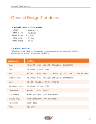
- 7. 7 Worldwide Oilfield Machine General Design Standards STANDARDS AND SPECIFICATIONS • API 6D • ASME B16.10 • ASME B16.34 • ASME B16.5 • ASME B 16.25 STANDARD MATERIALS WOM Floating Ball Valves can be supplied in a large assortment of materials for optimal performance in a variety of operating conditions. DESCRIPTION MATERIAL Body A216 WCC; A105; A352 LCC; CF8M/SS316 ; DUPLEX STEEL Seat NYLATRON; DEVLON; RPTFE Ball A216 WCC; A105; A352 LCC; CF8M/SS316; DUPLEX STEEL; 17-4PH; INCONEL End Connector A216 WCC; A105; A352 LCC; CF8M/SS316; DUPLEX STEEL Stem AISI4130; F316/SS316; 17-4PH; INCONEL Stem Thrust Washer NYLATRON; DEVLON; RPTFE Gland Plate A216 WCC; A105; AISI4130 Stud and Nut ASTM A193 B7/B7M; ASTM A193 2H/2HM Seals /O-Rings VITON SHORE 70/90; LOW TEMP V1289 Name Plate SS316; 304SS Plates A36; EN19 • ASME sec VIII • ASME sec II • ISO5211 • ISO 5208 • API 6FA
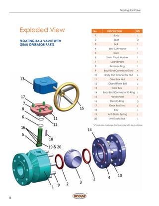
- 8. 8 Floating Ball Valve Exploded View FLOATING BALL VALVE WITH GEAR OPERATOR PARTS No. DESCRIPTION QTY 1 Body 1 2 Seat 2 3 Ball 1 4 End Connector 1 5 Stem 1 6 Stem Thrust Washer 1 7 Gland Plate 1 8 Retainer Ring 1 9 Body End Connector Stud x 10 Body End Connector Nut x 11 Gear Box Nut x 12 Gland Plate Bolt x 13 Gear Box 1 14 Body End Connector O-Ring 1 15 Handwheel 1 16 Stem O-Ring 3 17 Gear Box Stud x 18 Key 1 19 Anti Static Spring 1 20 Anti Static Ball 1 “x” indicates hardware that can vary with size and class
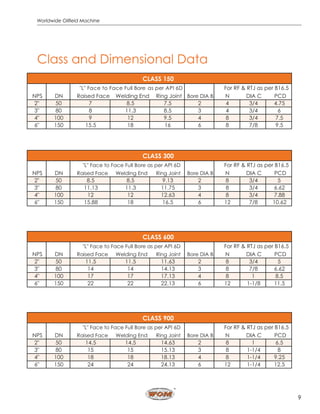
- 9. 9 Worldwide Oilfield Machine Raised Face Welding End Ring Joint N DIA C PCD 2" 50 7 8.5 7.5 2 4 3/4 4.75 3" 80 8 11.3 8.5 3 4 3/4 6 4" 100 9 12 9.5 4 8 3/4 7.5 6" 150 15.5 18 16 6 8 7/8 9.5 CLASS 150 DNNPS "L" Face to Face Full Bore as per API 6D Bore DIA B For RF & RTJ as per B16.5 Raised Face Welding End Ring Joint N DIA C PCD 2" 50 8.5 8.5 9.13 2 8 3/4 5 3" 80 11.13 11.3 11.75 3 8 3/4 6.62 4" 100 12 12 12.63 4 8 3/4 7.88 6" 150 15.88 18 16.5 6 12 7/8 10.62 CLASS 300 DNNPS "L" Face to Face Full Bore as per API 6D Bore DIA B For RF & RTJ as per B16.5 Raised Face Welding End Ring Joint N DIA C PCD 2" 50 11.5 11.5 11.63 2 8 3/4 5 3" 80 14 14 14.13 3 8 7/8 6.62 4" 100 17 17 17.13 4 8 1 8.5 6" 150 22 22 22.13 6 12 1-1/8 11.5 CLASS 600 DNNPS "L" Face to Face Full Bore as per API 6D Bore DIA B For RF & RTJ as per B16.5 Raised Face Welding End Ring Joint N DIA C PCD 2" 50 14.5 14.5 14.63 2 8 1 6.5 3" 80 15 15 15.13 3 8 1-1/4 8 4" 100 18 18 18.13 4 8 1-1/4 9.25 6" 150 24 24 24.13 6 12 1-1/4 12.5 CLASS 900 DNNPS "L" Face to Face Full Bore as per API 6D Bore DIA B For RF & RTJ as per B16.5 Class and Dimensional Data
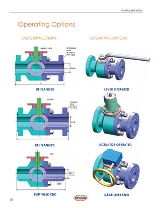
- 10. 10 Floating Ball Valve Pressure forces the Primary Seal against the ball, producing a positive upstream seal. If the Primary Seal is damaged, pressure forces the Secondary Seal against the ball, producing a positive upstream seal. END CONNECTIONS RF FLANGED RTJ FLANGED BUTT WELD END OPERATING OPTIONS LEVER OPERATED GEAR OPERATED ACTUATOR OPERATED Operating Options
- 11. 11 Worldwide Oilfield Machine Quality Policy The primary purpose of Worldwide Oilfield Machine, Inc. is to provide products and services that meet the customer’s needs and provide them with value. This philosophy will create gainful work for our employees and a profit for our stakeholders. Worldwide Oilfield Machine, Inc. is dedicated to providing the best possible product and/or service to its customers by having well-trained, enthusiastic employees and the effective implementation of this management system. It is the policy of Worldwide Oilfield Machine, Inc. to: • Operate in a safe, consistent and economical manner • Maintain conformance to the documented quality management system, including the applicable industry codes, standards and/or specifications and customer-specified requirements • Maintain compliance with statutory and regulatory requirements • Prevent nonconformities at all stages of design and manufacturing by implementing the requirements of this manual and supporting procedures • Ensure customer satisfaction • Foster an environment of continual improvement • Communicate this policy throughout Worldwide Oilfield Machine, Inc. and ensure that it is understood • Aggressively pursue the Mitigation of Systemic Risk™ through the implementation of this management system • Monitor and periodically review the management system, including stated objectives, and this policy for suitability and effectiveness
- 12. Disclaimer.Thiscatalogispublishedforinformationalpurposesonly.Allpreviouscatalogsarenotvalidandshouldnotbeusedasareferenceinanyform. www.womgroup.com facebook.com/womglobalgroup instagram.com/womglobalgroup twitter.com/womglobalgroup linkedin.com/company/worldwideoilfieldmachine Rev.January2020 We are Worldwide Oilfield Machine (WOM) - a global company pioneering Flow Control Solutions for the Surface & Subsea sectors of the oil & gas industry. Headquartered in Houston, Texas, we have manufacturing facilities, engineering centers, sales offices and assembly/testing workshops all over the world. Our strength is our robust infrastructure that allows us complete control over quality, costs and delivery. With more than 20 patents and noted accreditations, our very own R&D facilities and 24x7 service centers across the globe we have the required capabilities & resources to deliver all your manufacturing needs for the industry.

