Heat exchanger parallel flow
•
5 likes•7,174 views

The objective of this experiment is to calculate the rate of the heat transfer log mean temperature difference, and the overall heat transfer coefficient in case of Counter flow
Report
Share


Heat exchanger parallel flow
- 1. 1 Koya University Faculty of Engineering Chemical Engineering Department Laboratory of Heat Transfer Experiment Number Three Heat Exchanger (Parallel Flow) Instructor: Dr.Barham & Mrs.Farah Name of Student: Aree Salah Tahir Experiment Contacted on: 10/Dec/2014 Report Submitted on: 18/Dec /2014 Group:A
- 2. 2 List of content: Aim………………………………………………………….3 Introduction...…………………………….……………..….4 Background Theory ……………………………………….5 Procedure …………………………………………………..6 Equipment and components used........................................7 Calculation.............................................................................8 Plots………………………………………………………9-10 Discussion ………………………………………………….11 References ………………………………………………….12
- 3. 3 Aim: The objective of this experiment is to calculate the rate of the heat transfer log mean temperature difference, and the overall heat transfer coefficient in case of parallel flow.
- 4. 4 Introduction: Up to this point we have learned how to analyze conduction and con- vection heat transfer in various systems with different geometries. This information, however, is not very useful unless it can be applied to practical situations. For this reason we shall devote this experiment to a prototypical application of heat transfer analysis known as a heat exchanger. A heat exchanger is a device that efficiently transfers heat from a warmer fluid to a colder fluid. A device we are probably all familiar with is the automobile radiator. Other applications for heat exchangers are found in heating and air conditioning systems. Heat exchangers are categorized in many ways, but the two most common practices are, by the method of construction, and by the flow arrangements. The analysis for designing an effective heat exchanger is very important; after all who'd want to be caught on the side of a deserted desert road with an overheated engine! In this experiment we will study a concentric tube heat exchanger with parallel and counter flow. For the analysis of this heat exchanger we will need to find important quantities such as the heat transfer coeffi- cient, power emitted, absorbed, and lost, the log mean temperature dif- ference, and the overall efficiency to compare the two types of flow. {1}
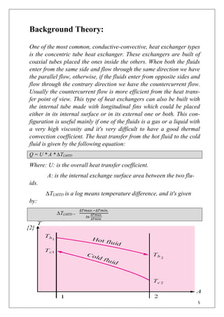
- 5. 5 Background Theory: One of the most common, conductive-convective, heat exchanger types is the concentric tube heat exchanger. These exchangers are built of coaxial tubes placed the ones inside the others. When both the fluids enter from the same side and flow through the same direction we have the parallel flow, otherwise, if the fluids enter from opposite sides and flow through the contrary direction we have the countercurrent flow. Usually the countercurrent flow is more efficient from the heat trans- fer point of view. This type of heat exchangers can also be built with the internal tube made with longitudinal fins which could be placed either in its internal surface or in its external one or both. This con- figuration is useful mainly if one of the fluids is a gas or a liquid with a very high viscosity and it's very difficult to have a good thermal convection coefficient. The heat transfer from the hot fluid to the cold fluid is given by the following equation: Q = U * A * ∆TLMTD Where: U: is the overall heat transfer coefficient. A: is the internal exchange surface area between the two flu- ids. ∆TLMTD is a log means temperature difference, and it's given by: ∆TLMTD = ∆𝑇𝑚𝑎𝑥.−∆𝑇𝑚𝑖𝑛. 𝑙𝑛 ∆𝑇𝑚𝑎𝑥. ∆𝑇𝑚𝑖𝑛. {2}
- 6. 6 Procedure: 1. Switch on master switch. 2. To Set hot water flow rate using cylinder and stopwatch 3. Switch on heater. Heating from an ambient temperature of 20 to 60°C requires approx. 20 min 4. Set parallel flow by open ball valve 2 and 3, and closed ball valve 1 and 4 in figure 5. Set a high cold-water flow rate with flow-control valve. Allow water to run briefly. 6. Carefully open bleeder valve for cold-water flow. 7. Close again when water emerges. 8. It is appropriate to bleed the hot-water circuit when warm, as bub- bles form while ever the temperature is still high. 9. Switch on pump. 10. Use flow-control valve to set high hot-water flow rate. Allow wa- ter to run briefly. 11. Carefully open bleeder valve for hot-water flow. 12. Close again when water emerges. Take care when system is hot: Danger of scalding as water emerges. {3}
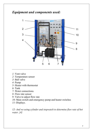
- 7. 7 Equipment and components used: 1- Vent valve 2- Temperature sensor 3- Ball valve 4- Pump 5- Heater with thermostat 6- Tank 7- Water connections 8- Flow rate sensor 9- Valve to adjust flow rate 10- Main switch and emergency pump and heater switches 11- Displays. 12- And we using cylinder and stopwatch to determine flaw rate of hot water. {4}
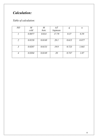
- 8. 8 Calculation: Table of calculation: NO M cold M hote ∆T logmean զͦ u 1 0.0077 0.014 17.79 0.37 0.59 2 0.0158 0.0149 20.1 0.615 0.877 3 0.0207 0.0153 19.9 0.723 1.041 4 0.0304 0.0149 20 0.747 1.07
- 9. 9 Plots: Plot (1) Plot (2) 17.79; 0.0077 20.1; 0.0158 19.9; 0.0207 20; 0.0304 y = 0.1217ln(x) - 0.3425 0 0.005 0.01 0.015 0.02 0.025 0.03 0.035 17.5 18 18.5 19 19.5 20 20.5 Mcold ∆T logmean Plot between M cold & ∆T logmean 0.37; 0.0077 0.615; 0.0158 0.723; 0.0207 0.747; 0.0304 0 0.005 0.01 0.015 0.02 0.025 0.03 0.035 0 0.1 0.2 0.3 0.4 0.5 0.6 0.7 0.8 Mcold զ ͦ Plot between M cold & զͦ
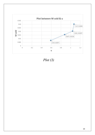
- 10. 10 Plot (3) 0.59; 0.0077 0.877; 0.0158 1.041; 0.0207 1.07; 0.0304 0 0.005 0.01 0.015 0.02 0.025 0.03 0.035 0 0.2 0.4 0.6 0.8 1 1.2 Mcold u Plot between M cold & u
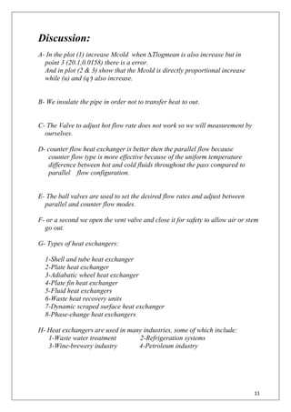
- 11. 11 Discussion: A- In the plot (1) increase Mcold when ∆Tlogmean is also increase but in point 3 (20.1,0.0158) there is a error. And in plot (2 & 3) show that the Mcold is directly proportional increase while (u) and (զ ͦ) also increase. B- We insulate the pipe in order not to transfer heat to out. C- The Valve to adjust hot flow rate does not work so we will measurement by ourselves. D- counter flow heat exchanger is better then the parallel flow because counter flow type is more effective because of the uniform temperature difference between hot and cold fluids throughout the pass compared to parallel flow configuration. E- The ball valves are used to set the desired flow rates and adjust between parallel and counter flow modes. F- or a second we open the vent valve and close it for safety to allow air or stem go out. G- Types of heat exchangers: 1-Shell and tube heat exchanger 2-Plate heat exchanger 3-Adiabatic wheel heat exchanger 4-Plate fin heat exchanger 5-Fluid heat exchangers 6-Waste heat recovery units 7-Dynamic scraped surface heat exchanger 8-Phase-change heat exchangers H- Heat exchangers are used in many industries, some of which include: 1-Waste water treatment 2-Refrigeration systems 3-Wine-brewery industry 4-Petroleum industry
- 12. 12 References: 1- http://www.engr.iupui.edu/~mrnalim/me314lab/lab10.htm 2- F.P Incropera and D.P DeWitt, "Fundamentals of Heat and Mass Transfer", 4th Edition, John Wiley and Sons, 2002. 3- Applied heat laboratory sheet by Koya University, college of engi- neering, department of chemical engineering. 4- http://www.gunt.de/static/s3452_1.php