Location via proxy:   [ UP ]  
[Report a bug]   [Manage cookies]                
SlideShare a Scribd company logo

1

Thermal Design of Heat
Exchanger Using HTRI
Umang Shah
FDC – Process
REAL, Jamnagar

2

2
Overview
❑ Type of Heat Exchangers
❑ Specifying Geometry
❑ Specifying Process Conditions and Physical
Properties
❑ MTD calculations & Output Summary

3

TYPE OF HEAT EXCHANGERS

4

4
Types of Heat Exchangers
1. Tubular
2. Non-tubular
1. Plate type
2. Hybrid

5

5
Tubular Heat Exchangers
1. Shell-and-Tube Heat Exchanger
2. Air-cooled Heat Exchanger
3. Double-pipe Heat Exchanger

6

6
Brief description of various HE’s
o Floating-head
o Fixed tube sheet
o U-tube

7

7
Floating-head
⚫ Removable tube bundle
⚫ Permits thermal expansion
⚫ Tube cleaning possible inside and outside
⚫ High cost

8

8
Fixed Tube sheet
– Simple construction, low cost
– Differential expansion not possible
– Outside of tubes cannot be cleaned

9

9
U-tube
– Permits thermal expansion
– Cleaning inside tubes difficult
– Low cost
– Removable tube bundle

10

SPECIFYING GEOMETRY

11

11
Modules of HTRI
⚫ Xchanger Suite
– Thermal performance and pressure drop analysis
⚫ Shell and tube exchangers, Xist
⚫ Hairpin exchanger, Xhpe
⚫ Jacketed pipe, Xjpe
⚫ Air coolers and Economizers, Xace
⚫ Plate and frame exchangers, Xphe
⚫ Tube vibration analysis, Xvib
⚫ Fire heaters, Xfh

12

12
Xist Geometry
⚫ TEMA types
– E, F, G, H, J, K, X
– Single and multipass tube arrangements
⚫ Double pipe
⚫ Reflux condensers
⚫ Falling film evaporators

13

13
Xist Geometry
⚫ Baffle types
– Single segmental
⚫ No tube in window (NTIW)
– Double Segmental
– RODbaffle
– EMbaffle
– Helical Baffle
– None

14

14
Baffle Types & Arrangement

15

15
Baffle Orientation
(Important for Horizontal Units)
⚫ Parallel Cut (Vertical
Cut)
– Permits condenser
drainage
– Mostly used in
condensers
⚫ Perpendicular cut
(Horizontal Cut)
– Better end zone
distribution
– Prevents separation
– Mostly used in single
phase

16

16
Xist Geometry
⚫ Limitations
– Inclined horizontal tube condensation up to 20°
– No high-finned tube

17

17
Calculation Types
– Rating
⚫ Specified geometry and Duty
– checking the performance of a specified heat exchanger
– Design
⚫ Unspecified geometry (some elements) and specified
duty
– performing the design for a specified duty
– Simulation
⚫ Specified geometry and unspecified duty
– predicting the performance of a specified geometry for a
given set of inlet (or outlet) conditions

18

18
Xist Required Geometry Inputs
(Rating Cases)
⚫ Shell type
⚫ Shall diameter (or number of tubes)
⚫ Number of shells in series and in parallel
⚫ Central baffle spacing (or number of cross
passes)
⚫ Tube data (length, outside diameter, pitch,
thickness, number of passes, pattern)

19

19
Xist Other Geometry
(Rating Cases)
– U-Tube
⚫ Full support plate
⚫ Location of Nozzle
– Reboiler geometry
⚫ Piping
⚫ Liquid static head
⚫ Bundle and kettle diameter
– Nozzle location

20

20
Xist Calculated Geometry
(Rating Cases)
⚫ Nozzle sizes
– Height under nozzle
⚫ Inlet and outlet baffle spacing
⚫ Tube-to-baffle, bundle-to-shell, baffle-to-shell
clearance
⚫ Baffle orientation
⚫ Pass lane width
User input overrides
Xist default calculations

21

21
Xist Design Modes
– Find geometry with
⚫ Minimum number of exchangers
– In series
– In parallel
⚫ Minimum area
⚫ Positive over design
– Grid design and Classic design options

22

22
Grid Design Mode
– In Input-Design-Geometry Panel
⚫ Minimum, maximum and steps
– Shell diameter
– Baffle spacing
– Number of tube passes
– Tube length
– Tube pitch ratio
– Shell and baffle type

23

23
Grid Design Mode
– Grid Design outlet panel contains
⚫ Red Trials
– Constraints not met
⚫ Bold Trial
– Largest over design
– Minimum area
– Constraints met
– Right click any trial to select it for rating

24

24
Classic Design Mode
– Sizing without grid for
⚫ Shell Diameter
⚫ Baffle spacing
⚫ Tube passes
– Required geometry includes
⚫ Tube diameter, length and wall thickness
⚫ Tube layout and pitch

25

25
Classic Design Mode
(Overall Procedure)
– Shortcut engine identifies geometry using classic design
logic
– Rigorous rating of shortcut engine design (base case)
– Rigorous rating of variations in base case (One size higher
and lower)
⚫ Shell diameter
⚫ Baffle spacing
⚫ Tube passes
– Best Rating is selected
⚫ Positive over design
⚫ Minimum Area

26

26
Classic Design Mode
(Shortcut Engine)
– Step 1 : Determine shell size and number of shells in series
and parallel
⚫ Add shell in series if LMTD F correction factor <0.7
⚫ Add shell in parallel if shell diameter > 60 in
⚫ Use minimum shell size to meet pressure drop and velocity
constraints
– Step 2 : Determine no. of cross passes and tube passes
⚫ Maximum no. of tube passes within DP and velocity
constraints
⚫ Determine number of cross passes to maximize over design
within pressure drop and velocity constraints

27

Specifying Process Conditions
and Physical Properties

28

28
Process Specification
(Required Conditions)
Rating or Design
(Duty not specified)
Five of six process
conditions
Rating or Design
(Duty specified)
Two of three process
conditions for each fluid
Simulation
(duty not specified)
Two of three process
condition for each side

29

29
Process Conditions
(Definitions)
– Hot / cold flow rates
– Hot / cold temperature, inlet / outlet
– Weight fraction vapor for two phase (required for isothermal
cases)
– Inlet pressure (required for two – phase)

30

30
Process Specification Rules
(General)
– If exchanger duty not specified, fluid duties need not match
⚫ Warning if mismatch more than 10%
⚫ Over design based on average
– Flow rate respected
⚫ Warning if mismatch more than 10%
– Specified temperatures always respected
– Exchanger duty always respected for over design
calculations

31

31
Process Specification Rules
(Two-Phase)
– Specified temperatures always respected ; weight
fraction vapor calculated
– If temperature not specified, weight fraction vapor
respected; temperature calculated

32

32
Process Specification Rules
(Rules of thumb)
– For ratings, specify duty (if known)
– Avoid specifying duty mismatch
⚫ For Xist shells-in-series, duty mismatch results in inaccurate
EMTD in the last shell
– Do not specify temperature if vapor fraction must be
used
– Ensure process conditions are realistic

33

33
Fluid Property Data
– Density
– Viscosity
⚫ Pressure drop
– Specific Heat
⚫ Single-phase heat release
– Temperature profile
– Thermal conductivity

34

34
Heat Release Data
– Temperature/enthalpy/weight fraction vapor data
⚫ Specific heat for single-phase
⚫ Vapor-liquid equilibrium model for two-phase
– Temperature profile
⚫ Mean temperature difference

35

35
Fluid Property Options
– Mixture properties via grid
⚫ User specified heat release only
– Temperature and Pressure
⚫ Reference pressures (1 minimum 12 maximum)
⚫ Reference temperature for each pressure (3 minimum and 30
maximum)

36

36
Mixture Properties Via Grid
– Heat Release Curve
⚫ Enthalpy of each reference pressure and temperature
⚫ Weight fraction vapor for two phase
– Property Grid
⚫ Required properties are identified on the Property grid panel
– Interpolation Methods
⚫ Quadratic fit between reference temperature - Default
⚫ Linear fit between reference pressures
Do not leave blanks
even if case runs

37

37
Built in Property Generator
– VMG thermo
⚫ Various Thermodynamic models available to generate
properties of multi-component feed
– HTRI
⚫ Useful for pure component

38

38
Basic Correlations for Thermal Design
Q = U * A * MTD
Q = heat transferred, kcal/h
U = Overall heat transfer coefficient, kcal/h m2 C
A = Heat transfer area, m2
MTD = Mean temperature difference, oC

39

39
Some fundamental correlations
Nu = 0.027 (Re)0.8 (Pr)0.33
hD/k = 0.027 (DG/μ)0.8 (cμ/k)0.33
h = 0.027 (DG/μ)0.8 (cμ/k)0.33 (k/D)
(a) h α G0.8
(b) h α μ-0.47
(c) h α k0.67
(d) h α c0.33

40

40
Impact on HTC
Physical Properties Impact on HTC, if
physical prop. increases,
Density Increase
Viscosity Decreases
Specific Heat Increase
Thermal Conductivity Increase

41

MTD Calculations and Output
Summary

42

42
Stream analysis

43

43
Shell side flow streams
⚫ A Stream
– Between tube OD and baffle hole
– Thermally ineffective
– Can be large for narrow baffle spacing
– Decreases with multi-segmental baffles
– Can plug with fouling deposits (check DP when A
stream is plugged)

44

44
Shell side flow streams
⚫ C Stream
– Between bundle and shell
– Typically should not exceed 20%
– Block by adding sealing strips or rods
– Partially effective for heat transfer (in contact
with heat transfer surface)

45

45
Shell side flow streams
⚫ F Stream
– Through pass lane clearance in bundle
– Typically should not exceed 20%
– Block by adding sealing strip or rods
– More effective for heat transfer than C stream,
less effective then A stream

46

46
Shell side flow streams
⚫ E Stream
– Between baffle and shell
– Ineffective (bypasses bundle)
– Can cause significant DTm correction
– Often caused by too small baffle cut and/or
spacing
– Must be sure that baffle-to-shell clearance not
more than TEMA recommendation

47

47
Temperature Profile Distortion

48

48
HTRI Delta Factor
(Xist Methods)
⚫ Temperature profile distortion due to
ineffective mixing of bypass stream
– E-Stream
– Portion of C Stream
⚫ d = 1 for effective mixing
⚫ 0.6 < d < 1.0 for ineffective mixing
– Empirical basis
– Mixing depends on baffle shell clearance,
number of baffles, bypass stream Reynolds
numbers

49

49
HTRI Delta Factor
(Xist Methods)
⚫ Explicit D method
– Exchanger rated assuming no distortion
– D calculated for each increment
– Each increment is de-rated
⚫ di = LMTD*/LMTDi

50

50
Output Summary
(Definition of selected entries)
⚫ Duty : Calculated Duty (average of hot and
cold fluid heat duty)
⚫ Area : Outside tube
⚫ Clean U : without considering fouling
⚫ Actual U : de-rated considering the
specified fouling factor
⚫ Required U : Based on available surface
area and EMTD
⚫ EMTD : Duty weighted average

51

51
Output Summary
% Over design = ------------------------------ X 100
U required
U actual – U required

52

52
Pressure Drop
⚫ Nozzle-to-nozzle change in pressure
– Frictional losses
– Momentum losses or gains
⚫ Momentum recovery in condenser
⚫ Momentum losses in reboiler
– Entrance and exit losses
– Turnaround losses in windows or bends
⚫ Static head handled differently
– Not included for single-phase
– Included in boiling cases
– Not included for condensation (except reflux condensation)

53

Thanks

More Related Content

HTRI PRESENTATION.pdf

  • 1. Thermal Design of Heat Exchanger Using HTRI Umang Shah FDC – Process REAL, Jamnagar
  • 2. 2 Overview ❑ Type of Heat Exchangers ❑ Specifying Geometry ❑ Specifying Process Conditions and Physical Properties ❑ MTD calculations & Output Summary
  • 3. TYPE OF HEAT EXCHANGERS
  • 4. 4 Types of Heat Exchangers 1. Tubular 2. Non-tubular 1. Plate type 2. Hybrid
  • 5. 5 Tubular Heat Exchangers 1. Shell-and-Tube Heat Exchanger 2. Air-cooled Heat Exchanger 3. Double-pipe Heat Exchanger
  • 6. 6 Brief description of various HE’s o Floating-head o Fixed tube sheet o U-tube
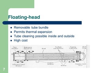
  • 7. 7 Floating-head ⚫ Removable tube bundle ⚫ Permits thermal expansion ⚫ Tube cleaning possible inside and outside ⚫ High cost
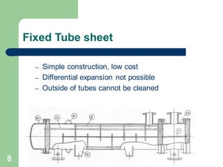
  • 8. 8 Fixed Tube sheet – Simple construction, low cost – Differential expansion not possible – Outside of tubes cannot be cleaned
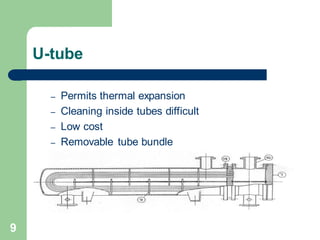
  • 9. 9 U-tube – Permits thermal expansion – Cleaning inside tubes difficult – Low cost – Removable tube bundle
  • 11. 11 Modules of HTRI ⚫ Xchanger Suite – Thermal performance and pressure drop analysis ⚫ Shell and tube exchangers, Xist ⚫ Hairpin exchanger, Xhpe ⚫ Jacketed pipe, Xjpe ⚫ Air coolers and Economizers, Xace ⚫ Plate and frame exchangers, Xphe ⚫ Tube vibration analysis, Xvib ⚫ Fire heaters, Xfh
  • 12. 12 Xist Geometry ⚫ TEMA types – E, F, G, H, J, K, X – Single and multipass tube arrangements ⚫ Double pipe ⚫ Reflux condensers ⚫ Falling film evaporators
  • 13. 13 Xist Geometry ⚫ Baffle types – Single segmental ⚫ No tube in window (NTIW) – Double Segmental – RODbaffle – EMbaffle – Helical Baffle – None
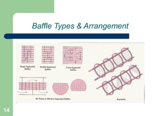
  • 14. 14 Baffle Types & Arrangement
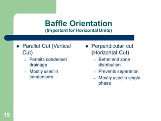
  • 15. 15 Baffle Orientation (Important for Horizontal Units) ⚫ Parallel Cut (Vertical Cut) – Permits condenser drainage – Mostly used in condensers ⚫ Perpendicular cut (Horizontal Cut) – Better end zone distribution – Prevents separation – Mostly used in single phase
  • 16. 16 Xist Geometry ⚫ Limitations – Inclined horizontal tube condensation up to 20° – No high-finned tube
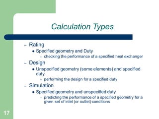
  • 17. 17 Calculation Types – Rating ⚫ Specified geometry and Duty – checking the performance of a specified heat exchanger – Design ⚫ Unspecified geometry (some elements) and specified duty – performing the design for a specified duty – Simulation ⚫ Specified geometry and unspecified duty – predicting the performance of a specified geometry for a given set of inlet (or outlet) conditions
  • 18. 18 Xist Required Geometry Inputs (Rating Cases) ⚫ Shell type ⚫ Shall diameter (or number of tubes) ⚫ Number of shells in series and in parallel ⚫ Central baffle spacing (or number of cross passes) ⚫ Tube data (length, outside diameter, pitch, thickness, number of passes, pattern)
  • 19. 19 Xist Other Geometry (Rating Cases) – U-Tube ⚫ Full support plate ⚫ Location of Nozzle – Reboiler geometry ⚫ Piping ⚫ Liquid static head ⚫ Bundle and kettle diameter – Nozzle location
  • 20. 20 Xist Calculated Geometry (Rating Cases) ⚫ Nozzle sizes – Height under nozzle ⚫ Inlet and outlet baffle spacing ⚫ Tube-to-baffle, bundle-to-shell, baffle-to-shell clearance ⚫ Baffle orientation ⚫ Pass lane width User input overrides Xist default calculations
  • 21. 21 Xist Design Modes – Find geometry with ⚫ Minimum number of exchangers – In series – In parallel ⚫ Minimum area ⚫ Positive over design – Grid design and Classic design options
  • 22. 22 Grid Design Mode – In Input-Design-Geometry Panel ⚫ Minimum, maximum and steps – Shell diameter – Baffle spacing – Number of tube passes – Tube length – Tube pitch ratio – Shell and baffle type
  • 23. 23 Grid Design Mode – Grid Design outlet panel contains ⚫ Red Trials – Constraints not met ⚫ Bold Trial – Largest over design – Minimum area – Constraints met – Right click any trial to select it for rating
  • 24. 24 Classic Design Mode – Sizing without grid for ⚫ Shell Diameter ⚫ Baffle spacing ⚫ Tube passes – Required geometry includes ⚫ Tube diameter, length and wall thickness ⚫ Tube layout and pitch
  • 25. 25 Classic Design Mode (Overall Procedure) – Shortcut engine identifies geometry using classic design logic – Rigorous rating of shortcut engine design (base case) – Rigorous rating of variations in base case (One size higher and lower) ⚫ Shell diameter ⚫ Baffle spacing ⚫ Tube passes – Best Rating is selected ⚫ Positive over design ⚫ Minimum Area
  • 26. 26 Classic Design Mode (Shortcut Engine) – Step 1 : Determine shell size and number of shells in series and parallel ⚫ Add shell in series if LMTD F correction factor <0.7 ⚫ Add shell in parallel if shell diameter > 60 in ⚫ Use minimum shell size to meet pressure drop and velocity constraints – Step 2 : Determine no. of cross passes and tube passes ⚫ Maximum no. of tube passes within DP and velocity constraints ⚫ Determine number of cross passes to maximize over design within pressure drop and velocity constraints
  • 27. Specifying Process Conditions and Physical Properties
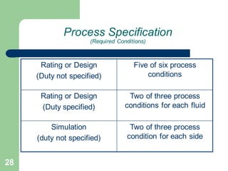
  • 28. 28 Process Specification (Required Conditions) Rating or Design (Duty not specified) Five of six process conditions Rating or Design (Duty specified) Two of three process conditions for each fluid Simulation (duty not specified) Two of three process condition for each side
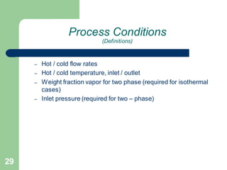
  • 29. 29 Process Conditions (Definitions) – Hot / cold flow rates – Hot / cold temperature, inlet / outlet – Weight fraction vapor for two phase (required for isothermal cases) – Inlet pressure (required for two – phase)
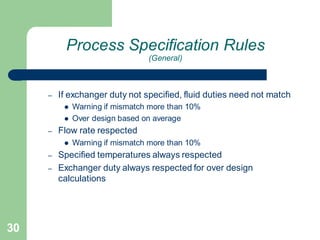
  • 30. 30 Process Specification Rules (General) – If exchanger duty not specified, fluid duties need not match ⚫ Warning if mismatch more than 10% ⚫ Over design based on average – Flow rate respected ⚫ Warning if mismatch more than 10% – Specified temperatures always respected – Exchanger duty always respected for over design calculations
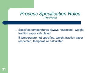
  • 31. 31 Process Specification Rules (Two-Phase) – Specified temperatures always respected ; weight fraction vapor calculated – If temperature not specified, weight fraction vapor respected; temperature calculated
  • 32. 32 Process Specification Rules (Rules of thumb) – For ratings, specify duty (if known) – Avoid specifying duty mismatch ⚫ For Xist shells-in-series, duty mismatch results in inaccurate EMTD in the last shell – Do not specify temperature if vapor fraction must be used – Ensure process conditions are realistic
  • 33. 33 Fluid Property Data – Density – Viscosity ⚫ Pressure drop – Specific Heat ⚫ Single-phase heat release – Temperature profile – Thermal conductivity
  • 34. 34 Heat Release Data – Temperature/enthalpy/weight fraction vapor data ⚫ Specific heat for single-phase ⚫ Vapor-liquid equilibrium model for two-phase – Temperature profile ⚫ Mean temperature difference
  • 35. 35 Fluid Property Options – Mixture properties via grid ⚫ User specified heat release only – Temperature and Pressure ⚫ Reference pressures (1 minimum 12 maximum) ⚫ Reference temperature for each pressure (3 minimum and 30 maximum)
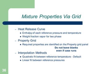
  • 36. 36 Mixture Properties Via Grid – Heat Release Curve ⚫ Enthalpy of each reference pressure and temperature ⚫ Weight fraction vapor for two phase – Property Grid ⚫ Required properties are identified on the Property grid panel – Interpolation Methods ⚫ Quadratic fit between reference temperature - Default ⚫ Linear fit between reference pressures Do not leave blanks even if case runs
  • 37. 37 Built in Property Generator – VMG thermo ⚫ Various Thermodynamic models available to generate properties of multi-component feed – HTRI ⚫ Useful for pure component
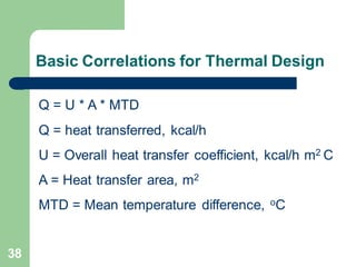
  • 38. 38 Basic Correlations for Thermal Design Q = U * A * MTD Q = heat transferred, kcal/h U = Overall heat transfer coefficient, kcal/h m2 C A = Heat transfer area, m2 MTD = Mean temperature difference, oC
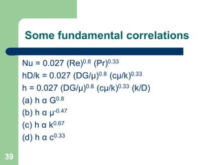
  • 39. 39 Some fundamental correlations Nu = 0.027 (Re)0.8 (Pr)0.33 hD/k = 0.027 (DG/μ)0.8 (cμ/k)0.33 h = 0.027 (DG/μ)0.8 (cμ/k)0.33 (k/D) (a) h α G0.8 (b) h α μ-0.47 (c) h α k0.67 (d) h α c0.33
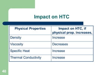
  • 40. 40 Impact on HTC Physical Properties Impact on HTC, if physical prop. increases, Density Increase Viscosity Decreases Specific Heat Increase Thermal Conductivity Increase
  • 41. MTD Calculations and Output Summary
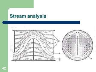
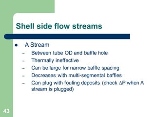
  • 43. 43 Shell side flow streams ⚫ A Stream – Between tube OD and baffle hole – Thermally ineffective – Can be large for narrow baffle spacing – Decreases with multi-segmental baffles – Can plug with fouling deposits (check DP when A stream is plugged)
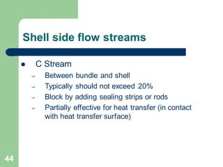
  • 44. 44 Shell side flow streams ⚫ C Stream – Between bundle and shell – Typically should not exceed 20% – Block by adding sealing strips or rods – Partially effective for heat transfer (in contact with heat transfer surface)
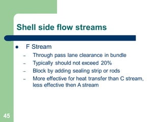
  • 45. 45 Shell side flow streams ⚫ F Stream – Through pass lane clearance in bundle – Typically should not exceed 20% – Block by adding sealing strip or rods – More effective for heat transfer than C stream, less effective then A stream
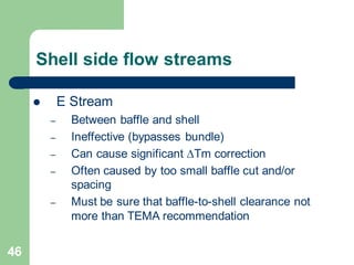
  • 46. 46 Shell side flow streams ⚫ E Stream – Between baffle and shell – Ineffective (bypasses bundle) – Can cause significant DTm correction – Often caused by too small baffle cut and/or spacing – Must be sure that baffle-to-shell clearance not more than TEMA recommendation
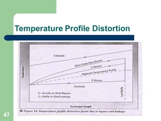
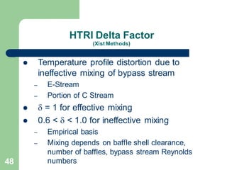
  • 48. 48 HTRI Delta Factor (Xist Methods) ⚫ Temperature profile distortion due to ineffective mixing of bypass stream – E-Stream – Portion of C Stream ⚫ d = 1 for effective mixing ⚫ 0.6 < d < 1.0 for ineffective mixing – Empirical basis – Mixing depends on baffle shell clearance, number of baffles, bypass stream Reynolds numbers
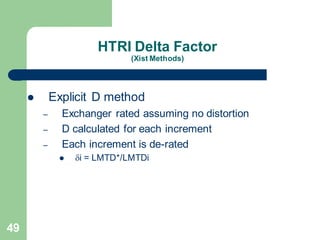
  • 49. 49 HTRI Delta Factor (Xist Methods) ⚫ Explicit D method – Exchanger rated assuming no distortion – D calculated for each increment – Each increment is de-rated ⚫ di = LMTD*/LMTDi
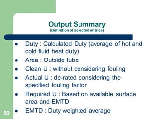
  • 50. 50 Output Summary (Definition of selected entries) ⚫ Duty : Calculated Duty (average of hot and cold fluid heat duty) ⚫ Area : Outside tube ⚫ Clean U : without considering fouling ⚫ Actual U : de-rated considering the specified fouling factor ⚫ Required U : Based on available surface area and EMTD ⚫ EMTD : Duty weighted average
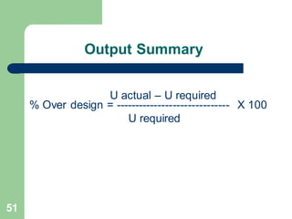
  • 51. 51 Output Summary % Over design = ------------------------------ X 100 U required U actual – U required
  • 52. 52 Pressure Drop ⚫ Nozzle-to-nozzle change in pressure – Frictional losses – Momentum losses or gains ⚫ Momentum recovery in condenser ⚫ Momentum losses in reboiler – Entrance and exit losses – Turnaround losses in windows or bends ⚫ Static head handled differently – Not included for single-phase – Included in boiling cases – Not included for condensation (except reflux condensation)