Hydraulic ciruits
•Download as PPT, PDF•
7 likes•10,278 views

Control of a single-acting and double-acting cylinder, regeneration, motor braking, speed control, synchronisation, fail safe, two handed, application of counterbalance, sequence, unloading, pressure reducing, pilot operated check valve
Report
Share


Hydraulic ciruits
- 1. Hydraulic circuits Control of a single-acting and double-acting cylinder, regeneration, motor braking, speed control, synchronisation, fail safe, two handed, application of counterbalance, sequence, unloading, pressure reducing, pilot operated check valve Industrial Fluid Power By Abhishek D. Patange Assistant Professor College of Engineering Pune
- 2. Definition of Hydraulic Circuits A hydraulic circuit is a group of components such as pumps, actuators, control valves, and conductors arranged so that they will perform a useful task. 1. Safety of operation 2. Performance of desired function 3. Efficiency of operation important considerations when analyzing or designing hydraulic circuits:
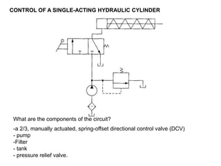
- 3. CONTROL OF A SINGLE-ACTING HYDRAULIC CYLINDER What are the components of the circuit? -a 2/3, manually actuated, spring-offset directional control valve (DCV) - pump -Filter - tank - pressure relief valve.
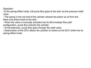
- 4. Operation -In the spring-offset mode, full pump flow goes to the tank via the pressure relief valve. - The spring in the rod end of the cylinder retracts the piston as oil from the blank end drains back to the tank. - When the valve is manually actuated into its left envelope flow path configuration, pump flow extends the cylinder. - At full extension, pump flow goes through the relief valve. - Deactivation of the DCV allows the cylinder to retract as the DCV shifts into its spring-offset mode.
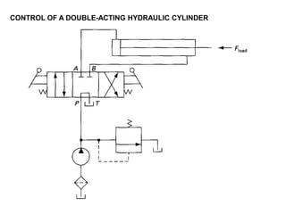
- 5. CONTROL OF A DOUBLE-ACTING HYDRAULIC CYLINDER
- 6. Operation 1. When the four-way valve is in its tandem design, the cylinder is hydraulically locked. Also, the pump is unloaded back to the tank at essentially atmospheric pressure. 2. When the four-way valve is actuated into the flow path configuration of the left envelope, the cylinder is extended against its load force Fload as oil flows from port P through port A. Also, oil in the rod end of the cylinder is free to flow back to the tank via the four-way valve from port B through port T. Note that the cylinder could not extend if this oil were not allowed to leave the rod end of the Cylinder. 3. When the four way valve is deactivated, the spring-centered envelope prevails, and the cylinder once again hydraulically locked. 4. When the four valve is actuated into the right envelope configuration, the cylinder retracts as oil flows from port P through port B. Oil in the blank end is returned to the tank via the flow path from port A to port T. 5. At the ends of the stroke, there is no system demand for oil. Thus, the pump flow goes through the relief valve at its pressure-level setting unless the four- way valve is deactivated. In any event, the system is protected from any cylinder overloads.
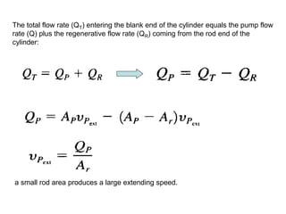
- 7. REGENERATIVE CYLINDER CIRCUIT It is used to speed up the extending speed of a double-acting hydraulic cylinder. Complete circuit. Partial circuit showing flow paths during cylinder extension stroke.
- 8. The total flow rate (QT) entering the blank end of the cylinder equals the pump flow rate (Q) plus the regenerative flow rate (QR) coming from the rod end of the cylinder: a small rod area produces a large extending speed.
- 9. Ratio of Extending and Retracting Speeds We know that the retracting speed (Vp) equals the pump flow rate divided by the difference of the piston and rod areas: When extending and retracting speeds are equal Extending speed of the piston, • Speed Equality Condition: When the piston area equals two times the rod area • the greater the ratio of piston area to rod area, the greater the ratio of extending speed to retracting speed. The Ratio
- 10. Load-Carrying Capacity During Extension The load-carrying capacity of a regenerative cylinder during extension is less than that obtained from a regular double-acting cylinder. The load-carrying capacity (Fload ) for a regenerative cylinder during extension equals the pressure times the piston rod area rather than the pressure times piston area.
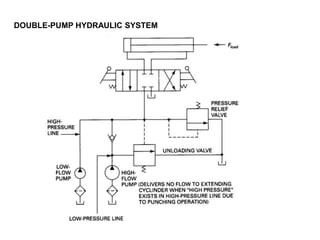
- 12. - An unloading valve is used to unload a pump. -The unloading valve opens when the cylinder reaches the end of its extension stroke because the check valve keeps high-pressure oil in the pilot line of the unloading valve. - When the DCV is shifted to retract the cylinder, the motion of the piston reduces the pressure in the pilot line of the unloading valve. -This resets the unloading valve until the cylinder is fully retracted, at which point the unloading valve unloads the pump. - The unloading valve unloads the pump at the ends of the extending and retraction strokes as well as in the spring-centered position of the DCV.
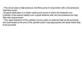
- 14. - The circuit uses a high-pressure, low-flow pump in conjunction with a low-pressure, high-flow pump. -A typical application is a sheet metal punch press in which the hydraulic ram (cylinder) must extend rapidly over a great distance with very low pressure but high flow-rate requirements. - This rapid extension of the cylinder occurs under no external load as the punching tool (connected to the end of the cylinder piston rod) approaches the sheet metal strip to be punched.
- 16. Purpose of CounterBalance ( back-pressure) Valve (CBV) To keep a vertically mounted hydraulic cylinder in the upward position while the pump is idling. -The counterbalance valve (CBV) is set to open at somewhat above the pressure required to prevent . -The vertical cylinder from descending due to the weight of its load. -This permits the cylinder to be forced downward when pressure is applied on the top. The open-center directional control valve unloads the pump. -The DCV is a solenoid-actuated, spring-centered valve with an open-center flow path configuration.
- 17. HYDRAULIC CYLINDER SEQUENCING CIRCUITS
- 18. Operation -a sequence valve is used - When the DCV is shifted into its left envelope mode, the left cylinder extends completely, and then the right cylinder extends. -If the DCV is then shifted into its right envelope mode, the right cylinder retracts fully, and then the left cylinder retracts. -This sequence of cylinder operation is controlled by the sequence valves. -The spring-centered position of the DCV locks both cylinders in place.
- 19. AUTOMATIC CYLINDER RECIPROCATING SYSTEM
- 20. -The circuit that produces continuous reciprocation of a hydraulic cylinder. -This is accomplished by using two sequence valves, each of which senses a stroke completion by the corresponding buildup of pressure. -Each check valve and corresponding pilot line prevents shifting of the four-way valve until the particular stroke of the cylinder has been completed. -The check valves are needed to allow pilot oil to leave either end of the DCV while pilot pressure is applied to the opposite end. -This permits the spool of the DCV to shift as required.
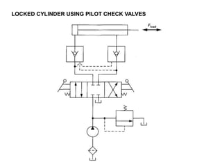
- 21. LOCKED CYLINDER USING PILOT CHECK VALVES
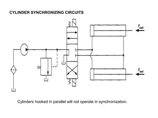
- 22. CYLINDER SYNCHRONIZING CIRCUITS Cylinders hooked in parallel will not operate in synchronization.
- 23. -if the two cylinders are identical, it would be necessary for the loads on the cylinders to be identical in order for them to extend in exact synchronization. -If the loads are not exactly identical (as is always the case), the cylinder with the smaller load would extend first because it would move at a lower pressure level - It should be pointed out that no two cylinders are really identical - differences in packing friction will vary from cylinder to cylinder.
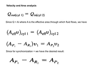
- 24. Cylinders Connected in Series Cylinders hooked in series will operate in synchronization.
- 25. Since Q = Ai where A is the effective area through which fluid flows, we have Since for synchronization = we have the desired result: Velocity and Area analysis
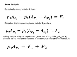
- 26. Force Analysis Summing forces on cylinder 1 yields Repeating this force summation on cylinder 2, we have Adding the preceding two equations together and noting that Ap2=Ap1 — AR1 and that p3 = 0 (due to the drain line to the tank), we obtain the desired result:
- 27. FAIL-SAFE CIRCUITS -Fail-safe circuits are those designed to prevent injury to the operator or damage to equipment. They prevent the system from accidentally falling on an operator They prevent overloading of the system.
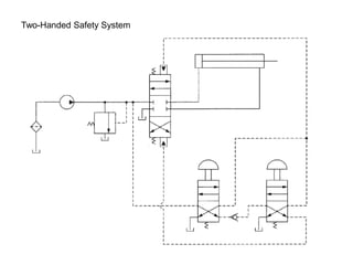
- 28. Protection from Inadvertent Cylinder Extension A fail-safe circuit that prevents the cylinder from accidentally falling in the event a hydraulic line ruptures or a person inadvertently operates the manual override on the pilot actuated directional control valve when the pump is not operating.
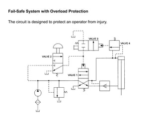
- 29. Fail-Safe System with Overload Protection The circuit is designed to protect an operator from injury.
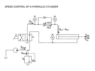
- 31. SPEED CONTROL OF A HYDRAULIC CYLINDER
- 32. 1. When the directional control valve is actuated, oil flows through the flow control valve to extend the cylinder. The extending speed of the cylinder depends on the setting (percent of full opening position) of the flow control valve (FCV). When the directional control valve is deactuated into its spring-offset mode, the cylinder retracts as oil flows from the cylinder to the oil tank through the check valve as well as the flow control valve. Operation
- 33. Analysis of Extending Speed Control The flow rate to the cylinder equals pump flow rate minus the flow rate through the PRV. The flow rate through the flow control valve (FCV) is governed by Eq.
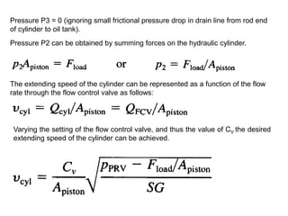
- 34. Pressure P3 = 0 (ignoring small frictional pressure drop in drain line from rod end of cylinder to oil tank). Pressure P2 can be obtained by summing forces on the hydraulic cylinder. The extending speed of the cylinder can be represented as a function of the flow rate through the flow control valve as follows: Varying the setting of the flow control valve, and thus the value of CV the desired extending speed of the cylinder can be achieved.
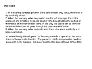
- 35. SPEED CONTROL OF A HYDRAULIC MOTOR
- 36. 1. In the spring-centered position of the tandem four-way valve, the motor is hydraulically locked. 2. When the four-way valve is actuated into the left envelope, the motor rotates in one direction. Its speed can be varied by adjusting the setting of the throttle of the flow control valve. In this way the speed can be infinitely varied as the excess oil goes through the pressure relief valve. 3. When the four-way valve is deactivated, the motor stops suddenly and becomes locked. Operation 4. When the right envelope of the four-way valve is in operation, the motor turns in the opposite direction. The pressure relief valve provides overload protection if, for example, the motor experiences an excessive torque load.
- 37. HYDRAULIC MOTOR BRAKING SYSTEM