Location via proxy:   [ UP ]  
[Report a bug]   [Manage cookies]                
SlideShare a Scribd company logo
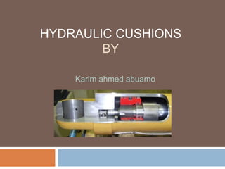
HYDRAULIC CUSHIONS
BY
Karim ahmed abuamo
Contents:
 Why is cylinder cushioning necessary?
 How it works?
 What is ideal cushioning?
 How is ideal cushioning achieved?
 Effect of varying operating pressure
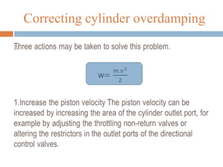
 Correcting cylinder overdamping
 Correcting cylinder underdamping
 Design for ideal cushioning
Why is cylinder cushioning
necessary?
 slow the piston down near the ends of the stroke
 lowers the stresses on the cylinder while reducing vibration
in the structure of which it is part
 If not effectively cushioned, the resultant slamming could
damage the piston and reduce the service life of the
actuator
How it works?
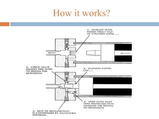
 Deceleration starts when the tapered plunger enters the
opening in the cap.
 This restricts the exhaust flow from the barrel to the port.
 During the last small portion of the stroke, the oil must
exhaust through an adjustable opening.
 The cushion design also incorporates a check valve to
allow free flow to the piston dur-ing direction reversal.
 The maximum pressure developed by cushions at the ends
of a cylinder must be considered since excessive pressure
buildup would rupture the cylinder.
What is ideal cushioning?
 Velocity of the piston is exactly zero when it reaches the
end of its travel.
 The sound of end cover contact is negligible
and the total cycle time is minimised.
 Thus, properly adjusted cushioning can have positive
effects on the working environment and on the total
working cycle time
How is ideal cushioning achieved?
 the first step is to ensure that the piston velocity
corresponds to that specified in the cushioning chart in the
main catalogue
 an electronic aid which can be attached to the outside of
the cylinder tube is now available and this enables the true
velocity of the piston to be determined quickly and easily.
 Ideal cushioning can only be achieved when maximum
kinetic energy is used.
Hydraulic cushions
 the adjusting screw is open by only a half to one turn,
Although the basic adjustment does prevent the piston
from striking the end cover, eliminating the risk of damage,
the cushioning is far from ideal. In addition, the extended
cushioning sequence may make it difficult to maintain the
cycle time.
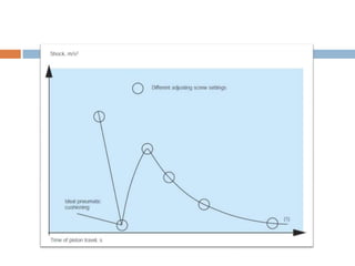
 The following diagram illustrates the sequence of events
which occurs when the adjusting screw is opened, all other
parameters being constant.
 Opening the adjusting screw a turn at a time moves the point to the left from the initial point
(1), which corresponds to the initial adjuster setting. During the first 2–3 turns, the cushioning
sequence is clearly seen to become progressively shorter. However, the end impact becomes
greater. The usual reaction is to cease adjustment at this point and to
 return the adjusting screw towards the original setting to counteract the severe shocks.
 However, ideal cushioning is achieved by continuing to open the screw a further 1–2 turns, at
which point – as the diagram shows – the end impact is minimal, with low noise and vibration
levels.
 If the adjusting screw is now opened further, the end impact will become considerably greater
without reducing the cycle time
 significantly. However, at the ideal pneumatic cushioning point, the total cycle time will be
reduced substantially as a result of the much faster cushioning sequence (a 20–40%
reduction is not unusual).
Effect of varying operating
pressure
 All of the parameters are assumed to be constant and only the
cushioning setting is adjusted.
 However, the operating pressure may fluctuate in large systems
with many users. The effects of this may make it worthwhile to
install large numbers of pressure regulators in critical applications.
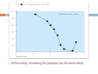
 Starting with ideal cushioning, with a minimum end impact at 6.3
bar, the shock increase sharply until, at 5 bar, the cylinder is
subjected to a shock equivalent to 30–40 times the mass the
cylinder is intended to cushion
 Apart from a high noise level, severe vibrations and a longer cycle
time, this shortens the life of the cylinder appreciably
 Unfortunately, increasing the pressure has the same result.

Correcting cylinder overdamping
2.Increase the moving mass A higher kinetic energy can
naturally be achieved by increasing the moving mass,
although this is not always so easy to achieve in practice.
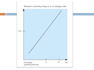
3.Reduce the operating pressure As the following diagram
shows, 100% of the maximum cushioning energy is utilised at
6.3 bar.
Hydraulic cushions
Correcting cylinder underdamping
If severe shock occurs regardless of the adjuster setting, the
cylinder is underdamped.
following action may be taken to solve the problem:
1. Reduce the piston velocity
2. Increase the operating pressure
3. Reduce the mass
A final alternative is to equip the cylinder with external
hydraulic shock absorbers.
Design for ideal cushioning
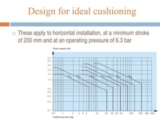
 These apply to horizontal installation, at a minimum stroke
of 200 mm and at an operating pressure of 6.3 bar
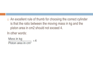
 An excellent rule of thumb for choosing the correct cylinder
is that the ratio between the moving mass in kg and the
piston area in cm2 should not exceed 4.
In other words:
 Thank you

More Related Content

Hydraulic cushions

  • 2. Contents:  Why is cylinder cushioning necessary?  How it works?  What is ideal cushioning?  How is ideal cushioning achieved?  Effect of varying operating pressure  Correcting cylinder overdamping  Correcting cylinder underdamping  Design for ideal cushioning
  • 3. Why is cylinder cushioning necessary?  slow the piston down near the ends of the stroke  lowers the stresses on the cylinder while reducing vibration in the structure of which it is part  If not effectively cushioned, the resultant slamming could damage the piston and reduce the service life of the actuator
  • 5.  Deceleration starts when the tapered plunger enters the opening in the cap.  This restricts the exhaust flow from the barrel to the port.  During the last small portion of the stroke, the oil must exhaust through an adjustable opening.  The cushion design also incorporates a check valve to allow free flow to the piston dur-ing direction reversal.  The maximum pressure developed by cushions at the ends of a cylinder must be considered since excessive pressure buildup would rupture the cylinder.
  • 6. What is ideal cushioning?  Velocity of the piston is exactly zero when it reaches the end of its travel.  The sound of end cover contact is negligible and the total cycle time is minimised.  Thus, properly adjusted cushioning can have positive effects on the working environment and on the total working cycle time
  • 7. How is ideal cushioning achieved?  the first step is to ensure that the piston velocity corresponds to that specified in the cushioning chart in the main catalogue  an electronic aid which can be attached to the outside of the cylinder tube is now available and this enables the true velocity of the piston to be determined quickly and easily.  Ideal cushioning can only be achieved when maximum kinetic energy is used.
  • 9.  the adjusting screw is open by only a half to one turn, Although the basic adjustment does prevent the piston from striking the end cover, eliminating the risk of damage, the cushioning is far from ideal. In addition, the extended cushioning sequence may make it difficult to maintain the cycle time.  The following diagram illustrates the sequence of events which occurs when the adjusting screw is opened, all other parameters being constant.
  • 10.  Opening the adjusting screw a turn at a time moves the point to the left from the initial point (1), which corresponds to the initial adjuster setting. During the first 2–3 turns, the cushioning sequence is clearly seen to become progressively shorter. However, the end impact becomes greater. The usual reaction is to cease adjustment at this point and to  return the adjusting screw towards the original setting to counteract the severe shocks.  However, ideal cushioning is achieved by continuing to open the screw a further 1–2 turns, at which point – as the diagram shows – the end impact is minimal, with low noise and vibration levels.  If the adjusting screw is now opened further, the end impact will become considerably greater without reducing the cycle time  significantly. However, at the ideal pneumatic cushioning point, the total cycle time will be reduced substantially as a result of the much faster cushioning sequence (a 20–40% reduction is not unusual).
  • 11. Effect of varying operating pressure  All of the parameters are assumed to be constant and only the cushioning setting is adjusted.  However, the operating pressure may fluctuate in large systems with many users. The effects of this may make it worthwhile to install large numbers of pressure regulators in critical applications.  Starting with ideal cushioning, with a minimum end impact at 6.3 bar, the shock increase sharply until, at 5 bar, the cylinder is subjected to a shock equivalent to 30–40 times the mass the cylinder is intended to cushion  Apart from a high noise level, severe vibrations and a longer cycle time, this shortens the life of the cylinder appreciably
  • 12.  Unfortunately, increasing the pressure has the same result.
  • 14. 2.Increase the moving mass A higher kinetic energy can naturally be achieved by increasing the moving mass, although this is not always so easy to achieve in practice. 3.Reduce the operating pressure As the following diagram shows, 100% of the maximum cushioning energy is utilised at 6.3 bar.
  • 16. Correcting cylinder underdamping If severe shock occurs regardless of the adjuster setting, the cylinder is underdamped. following action may be taken to solve the problem: 1. Reduce the piston velocity 2. Increase the operating pressure 3. Reduce the mass A final alternative is to equip the cylinder with external hydraulic shock absorbers.
  • 17. Design for ideal cushioning  These apply to horizontal installation, at a minimum stroke of 200 mm and at an operating pressure of 6.3 bar
  • 18.  An excellent rule of thumb for choosing the correct cylinder is that the ratio between the moving mass in kg and the piston area in cm2 should not exceed 4. In other words: