Introduction to CNC machine and Hardware.
•Download as PPTX, PDF•
25 likes•13,382 views

Complete detailing of cnc machine and its operations with its required hardware necessary for increasing its Automation and increasing its manufacturing capability. Also increase in complex shape manufacturing.
Report
Share


Introduction to CNC machine and Hardware.
- 1. INTRODUCTION TO CNC & HARDWARE Submitted By: Aman Kumar 1
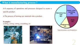
- 2. A sequence of operations and processes designed to create a specific product . The process of turning raw materials into a product . Examples: welding, casting, cutting, assembling, etc. Typical product cost breakdown What is manufacturing process ?
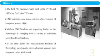
- 3. The first NC machines were built in the 1940s and 1950s by Prof. John T Parson. CNC machine came into existence after evolution of computer around 1980. Modern CNC Machine are improving further as the technology is changing with a variety of functions according to applications. In the early 1950s the Massachusetts Institute of Technology developed a more advanced vacuum tube computer called Whirlwind. History
- 4. To ensure that all U.S. military airplanes were manufactured identically after world war II the US Air Force invited several top companies to develop and manufacture numerical control systems which can handle the quantity and repeatability of machine. In 1952, The first three axis, Numerically controlled, tape-fed machine tool was created. A Cincinnati Milacron Hydro-Tel Vertical Spindle Milling (VMC) machine was retrofitted and controlled by the Whirlwind Computer. The controller was equipped with optical sensors and used a straight binary perforated tape to hold the instructions; The tape was read via a mechanical feeding mechanism. In 1954, Numerical control was announced to the public, and after three year the first Production NC machine was delivered and Installed. Cont…
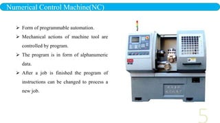
- 5. Numerical Control Machine(NC) Form of programmable automation. Mechanical actions of machine tool are controlled by program. The program is in form of alphanumeric data. After a job is finished the program of instructions can be changed to process a new job.
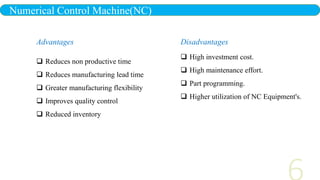
- 6. Numerical Control Machine(NC) Advantages Reduces non productive time Reduces manufacturing lead time Greater manufacturing flexibility Improves quality control Reduced inventory Disadvantages High investment cost. High maintenance effort. Part programming. Higher utilization of NC Equipment's.
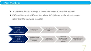
- 7. CNC Machine To overcome the shortcomings of the NC machines CNC machines evolved. CNC machines are the NC machines whose MCU is based on the micro computer rather than the hardwired controller. Elements of CNC machines are Part program Machine Control Unit Machine tool Features of CNC machines are: Storage of more than one part program In-process compensation Improved programming and operating features Adaptive control adjustments
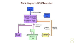
- 8. Block diagram of CNC Machine
- 9. Elements of CNC machines Elements of CNC machine tool essentially consists of the following parts: Part Program Program Input Device Machine Control Unit (MCU) Drive System Machine Tool Feedback System.
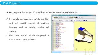
- 10. Part Program It controls the movement of the machine tool and on/off control of auxiliary functions such as spindle rotation and coolant. The coded instructions are composed of letters, numbers and symbols. A part program is a series of coded instructions required to produce a part.
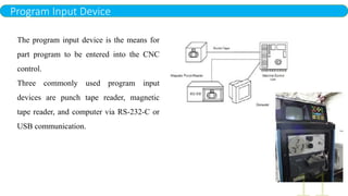
- 11. Program Input Device The program input device is the means for part program to be entered into the CNC control. Three commonly used program input devices are punch tape reader, magnetic tape reader, and computer via RS-232-C or USB communication.
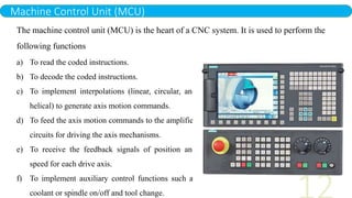
- 12. Machine Control Unit (MCU) The machine control unit (MCU) is the heart of a CNC system. It is used to perform the following functions a) To read the coded instructions. b) To decode the coded instructions. c) To implement interpolations (linear, circular, and helical) to generate axis motion commands. d) To feed the axis motion commands to the amplifier circuits for driving the axis mechanisms. e) To receive the feedback signals of position and speed for each drive axis. f) To implement auxiliary control functions such as coolant or spindle on/off and tool change.
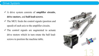
- 13. Drive System A drive system consists of amplifier circuits, drive motors, and ball lead-screws. The MCU feeds the control signals (position and speed) of each axis to the amplifier circuits. The control signals are augmented to actuate drive motors which in turn rotate the ball lead- screws to position the machine table.
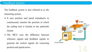
- 14. Feedback System The feedback system is also referred to as the measuring system. It uses position and speed transducers to continuously monitor the position at which the cutting tool is located at any particular instant. The MCU uses the difference between reference signals and feedback signals to generate the control signals for correcting position and speed errors.
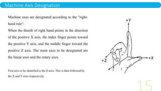
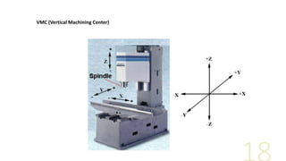
- 15. Machine Axis Designation Machine axes are designated according to the "right- hand rule“. When the thumb of right hand points in the direction of the positive X axis, the index finger points toward the positive Y axis, and the middle finger toward the positive Z axis. The main axes to be designated are the linear axes and the rotary axes. First axis to be identified is the Z-axis. This is then followed by the X and Y axes respectively.
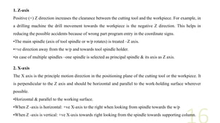
- 16. 1. Z-axis Positive (+) Z direction increases the clearance between the cutting tool and the workpiece. For example, in a drilling machine the drill movement towards the workpiece is the negative Z direction. This helps in reducing the possible accidents because of wrong part program entry in the coordinate signs. •The main spindle (axis of tool spindle or w/p rotates) is treated –Z axis. •+ve direction away from the w/p and towards tool spindle holder. •in case of multiple spindles –one spindle is selected as principal spindle & its axis as Z axis. 2. X-axis The X axis is the principle motion direction in the positioning plane of the cutting tool or the workpiece. It is perpendicular to the Z axis and should be horizontal and parallel to the work-holding surface wherever possible. •Horizontal & parallel to the working surface. •When Z -axis is horizontal: +ve X-axis to the right when looking from spindle towards the w/p •When Z -axis is vertical: +ve X-axis towards right looking from the spindle towards supporting column.
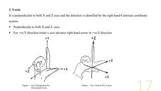
- 17. 3. Y-axis It is perpendicular to both X and Z axes and the direction is identified by the right hand Cartesian coordinate system. Perpendicular to both X-and Z -axis. For +ve Y direction rotate x axis advance right hand screw in +ve Z direction
- 18. VMC (Vertical Machining Center)
- 19. HMC (Horizontal Machining Center)
- 20. Common types of CNC machines CNC Lathe machine CNC Milling machine CNC Drilling machine CNC Grinding machine CNC Laser cutting machine Water jet cutting machine Electro discharge machine
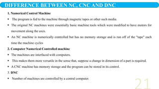
- 21. 1. Numerical Control Machine The program is fed to the machine through magnetic tapes or other such media. The original NC machines were essentially basic machine tools which were modified to have motors for movement along the axes. An NC machine is numerically controlled but has no memory storage and is run off of the "tape" each time the machine cycles 2. Computer Numerical Controlled machine The machines are interfaced with computers. This makes them more versatile in the sense that, suppose a change in dimension of a part is required. A CNC machine has memory storage and the program can be stored in its control. 3. DNC Number of machines are controlled by a central computer. DIFFERENCE BETWEEN NC, CNC AND DNC
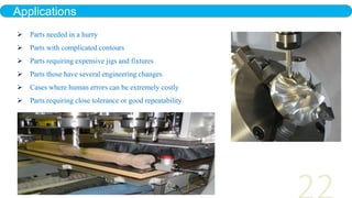
- 22. Applications Parts needed in a hurry Parts with complicated contours Parts requiring expensive jigs and fixtures Parts those have several engineering changes Cases where human errors can be extremely costly Parts requiring close tolerance or good repeatability
- 23. AUTOMATION Productivity Machine utilization is increased because more time is spent cutting and less time is taken by positioning. Reduced setup time increases utilization too. PROFIT increases as COST decreases and as PRODUCTIVITY increases. PRODUCTIVITY through AUTOMATION helping the workers to perform their tasks more efficiently Transfer of the skill of the operator to the machine ADVANTAGES OF CNC MACHINE
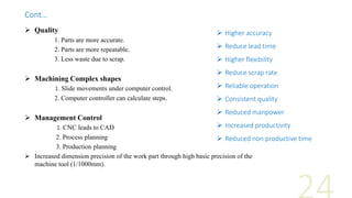
- 24. Quality 1. Parts are more accurate. 2. Parts are more repeatable. 3. Less waste due to scrap. Machining Complex shapes 1. Slide movements under computer control. 2. Computer controller can calculate steps. Management Control 1. CNC leads to CAD 2. Process planning 3. Production planning Increased dimension precision of the work part through high basic precision of the machine tool (1/1000mm). Higher accuracy Reduce lead time Higher flexibility Reduce scrap rate Reliable operation Consistent quality Reduced manpower Increased productivity Reduced non productive time Cont…
- 25. 1. Machine Cost is Higher than Conventional Machine. 2. Higher Maintenance Costs . 3. Higher Labor Costs . 4. Higher Machine Attachment Costs. 5. Higher Tooling Costs. 6. High maintenance requirements DISADVANTAGE OF CNC MACHINE
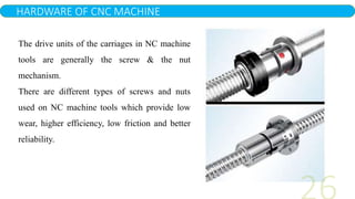
- 26. HARDWARE OF CNC MACHINE The drive units of the carriages in NC machine tools are generally the screw & the nut mechanism. There are different types of screws and nuts used on NC machine tools which provide low wear, higher efficiency, low friction and better reliability.
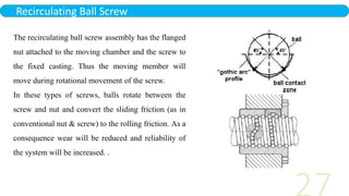
- 27. Recirculating Ball Screw The recirculating ball screw assembly has the flanged nut attached to the moving chamber and the screw to the fixed casting. Thus the moving member will move during rotational movement of the screw. In these types of screws, balls rotate between the screw and nut and convert the sliding friction (as in conventional nut & screw) to the rolling friction. As a consequence wear will be reduced and reliability of the system will be increased. .
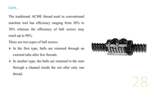
- 28. The traditional ACME thread used in conventional machine tool has efficiency ranging from 20% to 30% whereas the efficiency of ball screws may reach up to 90%. There are two types of ball screws. In the first type, balls are returned through an external tube after few threads. In another type, the balls are returned to the start through a channel inside the nut after only one thread. Cont…
- 29. Roller Screw These types of screws provide backlash-free movement and their efficiency is same as that of ball screws. These are capable of providing more accurate position control. Cost of the roller screws are more compared to ball screws. The thread form is triangular with an included angle of 90 degrees. There are two types of roller screws: Planetary and Recirculating screws.
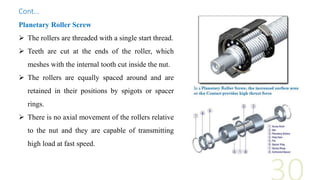
- 30. Planetary Roller Screw The rollers are threaded with a single start thread. Teeth are cut at the ends of the roller, which meshes with the internal tooth cut inside the nut. The rollers are equally spaced around and are retained in their positions by spigots or spacer rings. There is no axial movement of the rollers relative to the nut and they are capable of transmitting high load at fast speed. Cont…
- 31. Recirculating Roller Screw The rollers in this case are not threaded and are provided with a circular groove and are positioned circumferentially by a cage. There is some axial movement of the rollers relative to the nut. Each roller moves by a distance equal to the pitch of the screw for each rotation of the screw or nut and moves into an axial recess cut inside the nut and disengage from the threads on the screw and the nut and the other roller provides the driving power. Rollers in the recess are moved back by an edge cam in the nut. Recirculating roller screws are slower in operation, but are capable of transmitting high loads with greater accuracy.
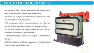
- 32. An Automatic Tool Changer is equipment that reduces cycle times by automatically changing tools between cuts. Automatic tool changers are differentiated by tool-to-tool time and the number of tools they can hold. CNC tool changers allow a machine to perform more than one function without requiring an operator to change the tooling. A CNC tool changer can quickly change the end effectors without the requirement of multiple robots. Tool changers can be a manual tool changers or automatic tool changers. A CNC tool changer ful fills the requirement of multiple tooling for a wide variety of machine tools AUTOMATIC TOOL CHANGER
- 33. Tool changer is equipment which is used in CNC machines to reduce the cycle time. The term applies to a wide variety of tooling, from indexable insert, single point tools to coded, preset tool holders for use in automatic tool changers. It includes power- actuated, cross-slide tooling and turret tool holders for single spindle chuckers, interchangeable- block boring tools. A number of basic types of tool holders are available that accommodate most face mills, end mills, drills, reamers, taps, boring tools, counter bores, countersinks, and spot facers. Arbor type cutters such as face mills and shell end mills are held in anarbor type tool holders. Shank type mills are held in positive lock holder. Drills, reamers and boring tools are held in a straight shank collet type holder. Taps are held in a tension and compression collet type holders. Why Tool Changer is needed?
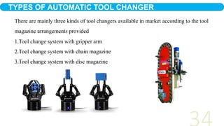
- 34. 1.Tool change system with gripper arm 2.Tool change system with chain magazine 3.Tool change system with disc magazine TYPES OF AUTOMATIC TOOL CHANGER There are mainly three kinds of tool changers available in market according to the tool magazine arrangements provided
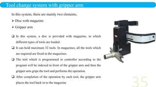
- 35. In this system, a disc is provided with magazine, in which different types of tools are loaded. It can hold maximum 32 tools. In magazines, all the tools which are required are fixed in the magazines. The tool which is programmed in controller according to the program will be indexed in front of the gripper arm and then the gripper arm grips the tool and performs the operation. After completion of the operation by each tool, the gripper arm places the tool back in to the magazine Tool change system with gripper arm In this system, there are mainly two elements, Disc with magazine Gripper arm
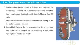
- 36. Tool Change system with chain magazine In this kind of system, a chain is provided with magazines for toolholding. This chain can hold numerous tools so it is used in heavy machineries. Starting from 32 it can hold more than 100 tools. These chain is indexed in front of the head stock directly as per the tool programmed position. In this kind of system there is no arrangement like gripper arm. The chain itself is indexed and the machining is done while keeping the tool in the chain only
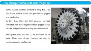
- 37. Tool change system with Disc magazine In this system, the tools are held in a big disc. This disc is not similar to the disc provided in gripper arm mechanism. In this disc, there are tool grippers provided separately for each magazine these grippers holds the tool and performs machining operation as well. This system disc can hold 32 to maximum of 64 tools. These type of tool changers are used in medium capacity machineries.
- 38. Automatic Guided Vehicle (AGV) What is an AGV? A Computer-Controlled, Non-manned, Electric Powered Vehicle Capable of Handling Material. Different Types of AGVs 1. Fork 2. Tow/Tugger 3. Unit Load 4. Custom
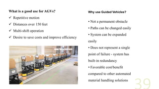
- 39. What is a good use for AGVs? Repetitive motion Distances over 150 feet Multi-shift operation Desire to save costs and improve efficiency • Not a permanent obstacle • Paths can be changed easily • System can be expanded easily • Does not represent a single point of failure - system has built-in redundancy • Favorable cost/benefit compared to other automated material handling solutions Why use Guided Vehicles?
- 41. How are they powered? Charge it! • Standard Charging (battery swap) • In-Vehicle (opportunity) Charging • Inductive Charging How do they know where to go? Guidance Methods • Optical – Tracks contrasting color • Wire – Embedded in floor • Inertial – Gyro with magnets in floor • Laser – Triangulation from reflective targets Cont…