Location via proxy:   [ UP ]  
[Report a bug]   [Manage cookies]                
SlideShare a Scribd company logo
International Research Journal of Engineering and Technology (IRJET) e-ISSN: 2395-0056
Volume: 06 Issue: 05 | May 2019 www.irjet.net p-ISSN: 2395-0072
© 2019, IRJET | Impact Factor value: 7.211 | ISO 9001:2008 Certified Journal | Page 6400
Electricity Generation by using Waste Heat
Prof. Tabish Shah1, Akshay S. Patil2, Manoj S. Bidgar3, Rupesh B. Shelake4, Pratik R. Shinde5
1Professor, 2UG Student, 3UG Student, 4UG Student, 5UG Student
Electrical Engineering Department
Sandip Institute of Engineering & Management, Nashik, Maharashtra, India
-------------------------------------------------------------------------***------------------------------------------------------------------------
Abstract - A thermoelectric generator (TEG), also called a
Seebeck generator, is a solid state device that converts heat
(temperature differences) directly into electrical energy
through a phenomenon called the Seebeck effect (a form of
thermoelectric effect). Thermoelectricgeneratorsfunction like
heat engines, but are less bulky and have no moving parts.
However, TEGs are typically more expensive and less efficient.
Thermoelectric generators could be used in power plants
in order to convert waste heat into additionalelectricalpower
and in automobiles as automotive thermoelectric generators
(ATGs) to increase fuel efficiency. Another application is
radioisotope thermoelectric generators which are used in
space probes, which has the same mechanism but use
radioisotopes to generate the required heat Peltier.
Key Words: Thermoelectric Generator, Heat Engine, Solid
State Device etc.
I. INTR.ODUCTION
As the dawn breaks, every day we come across some
new technology or development in the field of science. The
scope of this wide spectrum in which humans are
encouraged to find a better substitute for the older
technologies has made so many advancements to makeday-
to-day life easy. One such major point of focus today is to
replace the electricity with the non-conventional energy
resource-harvesting methods. In thesameway,heatcanbea
good source to produce power from it. The principle of
Seeback effect can be used for such applications. A German
physicist - Thomas Seebeack, first described it as long ago in
1820. Two metals with a common contact point, where the
potential developed due to the temperaturedifferencein the
other two ends of metals, is all about Seeback effect. Peltier
module also follows the same principle. We have used TEC-
12706 in our experimentations to know ways to optimize
the use of a Peltier module. This paper shows that heat
harvested from different heat sources generate different
amount of voltages and overall power. Experimentations
also showed that using different ways to extract heat from
the other side of the module made output voltage to vary
accordingly.
These days the demand of electricity is rising
tremendously with the growing industries and household
electrical appliances. To fulfil these daily requirements
different energy sources like coal, water, wind and solar
energy are employed at a very high cost. From all these
sources, energy is extracted and utilized but the demand for
power is still at large. Even though the world is fastchanging
and developing there are still many villages and far flung
areas where electricity is not reached and still a demand.
From some the power generation method after harvesting
energy, heat is simply wasted as by product into the
environment. If such heat can be converted even in a small
mill watt range, it can be reuse in domestic low power
lighting and in running low power consumption electronic
products. According to thermodynamics law of energy also
known as law of conservation of energy, energy cannot be
created nor destroy but can be transformed from one form
to another. Thermoelectric device which work with the
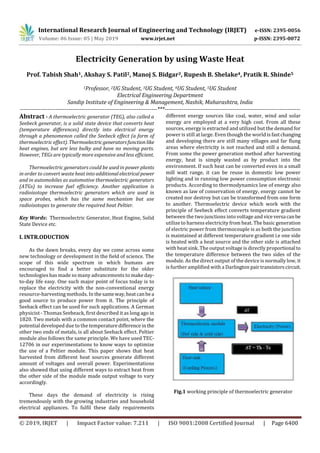
principle of Seebeck effect converts temperature gradient
between the two junctions into voltage and viceversa canbe
utilize to harness electricity from heat. The basic generation
of electric power from thermocouple is as both the junction
is maintained at different temperature gradient i.e one side
is heated with a heat source and the other side is attached
with heat sink. The output voltage is directly proportional to
the temperature difference between the two sides of the
module. As the direct output of the device is normally low, it
is further amplified with a Darlingtonpairtransistorscircuit.
Fig.1 working principle of thermoelectric generator
International Research Journal of Engineering and Technology (IRJET) e-ISSN: 2395-0056
Volume: 06 Issue: 05 | May 2019 www.irjet.net p-ISSN: 2395-0072
© 2019, IRJET | Impact Factor value: 7.211 | ISO 9001:2008 Certified Journal | Page 6401
II. PROBLEM STATEMENT
Some developing countries and most populated
industrialized countries (India china Mongolia Korea) etc.
have average of 3 to 10 hours of daily power-cuts because
the increase in demand of consumer utilization electricity
exceeds so that the production of electrical energy is lesser
then the consumer demand. And also shortage of fossil fuel
and coal i.e. about 60% of electricity is generated from fossil
fuels. (Oil and gas) are imported from Arabian countries. So
that pollution also may occur due to the combustion of this
fossil fuel. And also the generating the power from these
conventional sources may lead to harmful environment and
pollute the nature. In the new generationtheyaredepending
upon the rechargeable batteries or diesel /petrol engineetc.
when there is no power and at the timeofloadshedding. The
use of generator is common in industrial and commercial
sector. This ultimately increases the shortage of power and
more cost.
THERMOELECTRIC OPERATING MODES
1. COOLING MODE
Alternating P and N type TE elements are wired electrically
in series, and thermally in parallel. As the current passes
through semiconductor elements, Peltier cooling lowersthe
temperature of the TEG cold side.
2. HEATING MODE
Reverse the polarity of the current. The previously hot side
starts to cool and the cooler side now acts as the hot surface.
3. POWER GENERATION MODE
When a temperature difference is imposed acrossthedevice
by adding an external heat source, the heat passing through
the device is converted to electrical power. As the heat
travels, power through the device is created. As the
temperature difference increases, power output also
increases system description and methodology.
III. BLOCK DIAGRAM
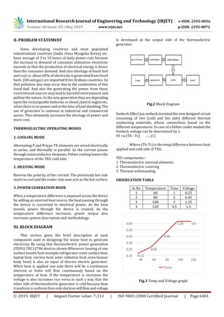
This section gives the brief description of each
component used in designing the waste heat to generate
electricity By using this thermoelectric power generation
(TEPG) TEC12706 devices shown Whenever heating of one
surface (waste heat example refrigerator outer surfaceheat,
laptop heat, ion box heat, solar radiation heat ,even human
body heat) is also an input of thermo electric generator.
When heat is applied one side there will be a continuous
electron or holes will flow continuously based on the
temperature of heat. If the temperature is increases the
voltage is also increases vice versa in such a way that the
other side of thermoelectric generator is cold because heat
transform is uniform then onlyelectron will flowandvoltage
is developed at the output side of the thermoelectric
generator.
Fig.2 Block Diagram
Seebeck Effect Jon seebeck inventedthenewdesignedcircuit
consisting of two (cold and hot side) different thermal
conducting materials, whose connections based on the
different temperatures. In case of a Peltiercoolermodulethe
Seebeck voltage can be determined by 1.
VS =α (Th −Tc) ……(1)
Where (Th-Tc) is the temp difference between heat
applied and cold side of TEG.
TEG components:-
1. Thermoelectric internal elements
2. Thermoelectric covering
3. Thermal withstanding
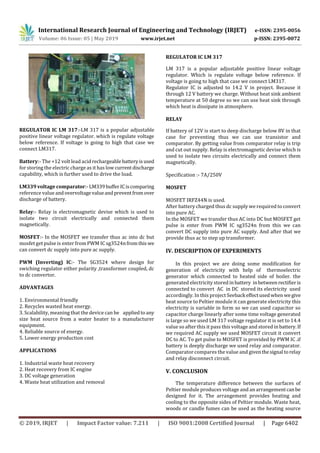
OBSERVATION TABLE
Sr.No Temperature Time Voltage
1 60 1 0.25
2 80 2 0.45
3 100 3 1.25
4 120 4.5 1.5
Fig.3 Temp and Voltage graph
International Research Journal of Engineering and Technology (IRJET) e-ISSN: 2395-0056
Volume: 06 Issue: 05 | May 2019 www.irjet.net p-ISSN: 2395-0072
© 2019, IRJET | Impact Factor value: 7.211 | ISO 9001:2008 Certified Journal | Page 6402
REGULATOR IC LM 317:-LM 317 is a popular adjustable
positive linear voltage regulator. which is regulate voltage
below reference. If voltage is going to high that case we
connect LM317.
Battery:- The +12 volt lead acidrechargeable batteryisused
for storing the electric charge as it has low currentdischarge
capability, which is further used to drive the load.
LM339 voltage comparator:-LM339bufferICiscomparing
reference value andovervoltagevalueandpreventfromover
discharge of battery.
Relay:- Relay is electromagnetic devise which is used to
isolate two circuit electrically and connected them
magnetically.
MOSFET:- In the MOSFET we transfer thus ac into dc but
mosfet get pulse is enter from PWM IC sg3524nfromthis we
can convert dc supply into pure ac supply.
PWM (Inverting) IC:- The SG3524 where design for
swiching regulator either polarity ,transformer coupled, dc
to dc convertor.
ADVANTAGES
1. Environmental friendly
2. Recycles wasted heat energy.
3. Scalability, meaning that the device can be appliedto any
size heat source from a water heater to a manufacturer
equipment.
4. Reliable source of energy.
5. Lower energy production cost
APPLICATIONS
1. Industrial waste heat recovery
2. Heat recovery from IC engine
3. DC voltage generation
4. Waste heat utilization and removal
REGULATOR IC LM 317
LM 317 is a popular adjustable positive linear voltage
regulator. Which is regulate voltage below reference. If
voltage is going to high that case we connect LM317.
Regulator IC is adjusted to 14.2 V in project. Because it
through 12 V battery we charge. Without heat sink ambient
temperature at 50 degree so we can use heat sink through
which heat is dissipate in atmosphere.
RELAY
If battery of 12V is start to deep discharge below 8V in that
case for preventing thus we can use transistor and
comparator. By getting value from comparator relay is trip
and cut out supply. Relay is electromagnetic devise which is
used to isolate two circuits electrically and connect them
magnetically.
Specification :- 7A/250V
MOSFET
MOSFET IRFZ44N is used.
After battery charged thus dc supply we required to convert
into pure AC.
In the MOSFET we transfer thus AC into DC but MOSFET get
pulse is enter from PWM IC sg3524n from this we can
convert DC supply into pure AC supply. And after that we
provide thus ac to step up transformer.
IV. DESCRIPTION OF EXPERIMENTS
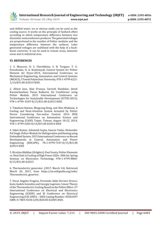
In this project we are doing some modification for
generation of electricity with help of thermoelectric
generator which connected to heated side of boiler. the
generated electricity stored inbattery inbetween rectifieris
connected to convert AC in DC stored its electricity used
accordingly. In this project Seeback effectusedwhen we give
heat source to Peltier module it can generate electricity this
electricity is variable in form so we can used capacitor so
capacitor charge linearly after some time voltage generated
is large so we used LM 317 voltage regulator it is set to 14.4
value so after this it pass this voltage and stored inbattery.If
we required AC supply we used MOSFET circuit it convert
DC to AC. To get pulse to MOSFET is provided by PWM IC .if
battery is deeply discharge we used relay and comparator.
Comparator compares the value and giventhesignal torelay
and relay disconnect circuit.
V. CONCLUSION
The temperature difference between the surfaces of
Peltier module produces voltage and an arrangementcanbe
designed for it. The arrangement provides heating and
cooling to the opposite sides of Peltier module. Waste heat,
woods or candle fumes can be used as the heating source
International Research Journal of Engineering and Technology (IRJET) e-ISSN: 2395-0056
Volume: 06 Issue: 05 | May 2019 www.irjet.net p-ISSN: 2395-0072
© 2019, IRJET | Impact Factor value: 7.211 | ISO 9001:2008 Certified Journal | Page 6403
and chilled water, ice or nitrous oxide can be used as the
cooling source. It works on the principle of Seebeck effect
according to which temperature difference between two
dissimilar semiconductorsproduces.Thegeneratedvoltages
are proportional to the number of Peltier modules and the
temperature difference between the surfaces. Later
generated voltages are stabilized with the help of a buck-
boost converter. It can be used in remote areas, domestic
areas and in industrial area.
VI. REFERENCES
1. S. Musorov, D. S. Chertikhina, S. N. Torgaev, T. G.
Evtushenko, O. A. Kozhemyak, Control System for Peltier
Element Air Dryer-2014, International Conference on
Mechanical Engineering, Automation and Control Systems
(MEACS),ITomsk Polytechnic University,978-1-4799-6221-
1/14/$31.00 ©2014 IEEE.
2. Allwin Jose, Alan D’souza, Sarvesh Dandekar, Jitesh
Karamchandani, Pavan Kulkarni, Air Conditioner using
Peltier Module, 2015 International Conference on
Technologies for Sustainable Development (ICTSD-2015),
978-1-4799- 8187-8/15/$31.00 ©2015 IEEE.
3. Takafumi Hatano, Mingcong Deng, and Shin Wakitani, A
Cooling and Heat-retention System Actuated by Peltier
Device Considering Fan-motor Control, 2014 IEEE
International Conference on Automation Science and
Engineering (CASE) Taipei, Taiwan, August 18-22, 2014,
978-1-4799-5283-0/14/$31.00 ©2014 IEEE
4. Saket Kumar, Ashutosh Gupta, Gaurav Yadav, Hemender
Pal Singh, Peltier Module for RefrigerationandHeatingusing
Embedded System,2015International ConferenceonRecent
Developments in Control, Automation and Power
Engineering (RDCAPE), 78-1-4799-7247-0/15/$31.00
©2015 IEEE
5. Niculina Bădălan (Drăghici), Paul Svasta, Peltier Elements
vs. Heat Sink in Cooling of High Power LEDs- 38thInt.Spring
Seminar on Electronics Technology, 978-1-4799-8860-
0/15/$31.00 ©2015
6. Thermoelectric generator. (2017, March 14). Retrieved
March 20, 2017, from https://en.wikipedia.org/wiki/
Thermoelectric_genertor.
7. Oscar Angeles Fragoso, Fernando Adán Serrano Orosco,
Jesús Audelo González and Georgiy Logvinov, Linear Theory
of the Thermoelectric Cooling BasedonthePeltierEffect-2nd
International Conference on Electrical and Electronics
Engineering (ICEEE) and XI Conference on Electrical
Engineering (CIE 2005)- - IEEE Catalog Number: 05EX1097
ISBN: 0-7803-9230-2/05/$20.00 ©2005 IEEE.

More Related Content

IRJET- Electricity Generation by using Waste Heat

  • 1. International Research Journal of Engineering and Technology (IRJET) e-ISSN: 2395-0056 Volume: 06 Issue: 05 | May 2019 www.irjet.net p-ISSN: 2395-0072 © 2019, IRJET | Impact Factor value: 7.211 | ISO 9001:2008 Certified Journal | Page 6400 Electricity Generation by using Waste Heat Prof. Tabish Shah1, Akshay S. Patil2, Manoj S. Bidgar3, Rupesh B. Shelake4, Pratik R. Shinde5 1Professor, 2UG Student, 3UG Student, 4UG Student, 5UG Student Electrical Engineering Department Sandip Institute of Engineering & Management, Nashik, Maharashtra, India -------------------------------------------------------------------------***------------------------------------------------------------------------ Abstract - A thermoelectric generator (TEG), also called a Seebeck generator, is a solid state device that converts heat (temperature differences) directly into electrical energy through a phenomenon called the Seebeck effect (a form of thermoelectric effect). Thermoelectricgeneratorsfunction like heat engines, but are less bulky and have no moving parts. However, TEGs are typically more expensive and less efficient. Thermoelectric generators could be used in power plants in order to convert waste heat into additionalelectricalpower and in automobiles as automotive thermoelectric generators (ATGs) to increase fuel efficiency. Another application is radioisotope thermoelectric generators which are used in space probes, which has the same mechanism but use radioisotopes to generate the required heat Peltier. Key Words: Thermoelectric Generator, Heat Engine, Solid State Device etc. I. INTR.ODUCTION As the dawn breaks, every day we come across some new technology or development in the field of science. The scope of this wide spectrum in which humans are encouraged to find a better substitute for the older technologies has made so many advancements to makeday- to-day life easy. One such major point of focus today is to replace the electricity with the non-conventional energy resource-harvesting methods. In thesameway,heatcanbea good source to produce power from it. The principle of Seeback effect can be used for such applications. A German physicist - Thomas Seebeack, first described it as long ago in 1820. Two metals with a common contact point, where the potential developed due to the temperaturedifferencein the other two ends of metals, is all about Seeback effect. Peltier module also follows the same principle. We have used TEC- 12706 in our experimentations to know ways to optimize the use of a Peltier module. This paper shows that heat harvested from different heat sources generate different amount of voltages and overall power. Experimentations also showed that using different ways to extract heat from the other side of the module made output voltage to vary accordingly. These days the demand of electricity is rising tremendously with the growing industries and household electrical appliances. To fulfil these daily requirements different energy sources like coal, water, wind and solar energy are employed at a very high cost. From all these sources, energy is extracted and utilized but the demand for power is still at large. Even though the world is fastchanging and developing there are still many villages and far flung areas where electricity is not reached and still a demand. From some the power generation method after harvesting energy, heat is simply wasted as by product into the environment. If such heat can be converted even in a small mill watt range, it can be reuse in domestic low power lighting and in running low power consumption electronic products. According to thermodynamics law of energy also known as law of conservation of energy, energy cannot be created nor destroy but can be transformed from one form to another. Thermoelectric device which work with the principle of Seebeck effect converts temperature gradient between the two junctions into voltage and viceversa canbe utilize to harness electricity from heat. The basic generation of electric power from thermocouple is as both the junction is maintained at different temperature gradient i.e one side is heated with a heat source and the other side is attached with heat sink. The output voltage is directly proportional to the temperature difference between the two sides of the module. As the direct output of the device is normally low, it is further amplified with a Darlingtonpairtransistorscircuit. Fig.1 working principle of thermoelectric generator
  • 2. International Research Journal of Engineering and Technology (IRJET) e-ISSN: 2395-0056 Volume: 06 Issue: 05 | May 2019 www.irjet.net p-ISSN: 2395-0072 © 2019, IRJET | Impact Factor value: 7.211 | ISO 9001:2008 Certified Journal | Page 6401 II. PROBLEM STATEMENT Some developing countries and most populated industrialized countries (India china Mongolia Korea) etc. have average of 3 to 10 hours of daily power-cuts because the increase in demand of consumer utilization electricity exceeds so that the production of electrical energy is lesser then the consumer demand. And also shortage of fossil fuel and coal i.e. about 60% of electricity is generated from fossil fuels. (Oil and gas) are imported from Arabian countries. So that pollution also may occur due to the combustion of this fossil fuel. And also the generating the power from these conventional sources may lead to harmful environment and pollute the nature. In the new generationtheyaredepending upon the rechargeable batteries or diesel /petrol engineetc. when there is no power and at the timeofloadshedding. The use of generator is common in industrial and commercial sector. This ultimately increases the shortage of power and more cost. THERMOELECTRIC OPERATING MODES 1. COOLING MODE Alternating P and N type TE elements are wired electrically in series, and thermally in parallel. As the current passes through semiconductor elements, Peltier cooling lowersthe temperature of the TEG cold side. 2. HEATING MODE Reverse the polarity of the current. The previously hot side starts to cool and the cooler side now acts as the hot surface. 3. POWER GENERATION MODE When a temperature difference is imposed acrossthedevice by adding an external heat source, the heat passing through the device is converted to electrical power. As the heat travels, power through the device is created. As the temperature difference increases, power output also increases system description and methodology. III. BLOCK DIAGRAM This section gives the brief description of each component used in designing the waste heat to generate electricity By using this thermoelectric power generation (TEPG) TEC12706 devices shown Whenever heating of one surface (waste heat example refrigerator outer surfaceheat, laptop heat, ion box heat, solar radiation heat ,even human body heat) is also an input of thermo electric generator. When heat is applied one side there will be a continuous electron or holes will flow continuously based on the temperature of heat. If the temperature is increases the voltage is also increases vice versa in such a way that the other side of thermoelectric generator is cold because heat transform is uniform then onlyelectron will flowandvoltage is developed at the output side of the thermoelectric generator. Fig.2 Block Diagram Seebeck Effect Jon seebeck inventedthenewdesignedcircuit consisting of two (cold and hot side) different thermal conducting materials, whose connections based on the different temperatures. In case of a Peltiercoolermodulethe Seebeck voltage can be determined by 1. VS =α (Th −Tc) ……(1) Where (Th-Tc) is the temp difference between heat applied and cold side of TEG. TEG components:- 1. Thermoelectric internal elements 2. Thermoelectric covering 3. Thermal withstanding OBSERVATION TABLE Sr.No Temperature Time Voltage 1 60 1 0.25 2 80 2 0.45 3 100 3 1.25 4 120 4.5 1.5 Fig.3 Temp and Voltage graph
  • 3. International Research Journal of Engineering and Technology (IRJET) e-ISSN: 2395-0056 Volume: 06 Issue: 05 | May 2019 www.irjet.net p-ISSN: 2395-0072 © 2019, IRJET | Impact Factor value: 7.211 | ISO 9001:2008 Certified Journal | Page 6402 REGULATOR IC LM 317:-LM 317 is a popular adjustable positive linear voltage regulator. which is regulate voltage below reference. If voltage is going to high that case we connect LM317. Battery:- The +12 volt lead acidrechargeable batteryisused for storing the electric charge as it has low currentdischarge capability, which is further used to drive the load. LM339 voltage comparator:-LM339bufferICiscomparing reference value andovervoltagevalueandpreventfromover discharge of battery. Relay:- Relay is electromagnetic devise which is used to isolate two circuit electrically and connected them magnetically. MOSFET:- In the MOSFET we transfer thus ac into dc but mosfet get pulse is enter from PWM IC sg3524nfromthis we can convert dc supply into pure ac supply. PWM (Inverting) IC:- The SG3524 where design for swiching regulator either polarity ,transformer coupled, dc to dc convertor. ADVANTAGES 1. Environmental friendly 2. Recycles wasted heat energy. 3. Scalability, meaning that the device can be appliedto any size heat source from a water heater to a manufacturer equipment. 4. Reliable source of energy. 5. Lower energy production cost APPLICATIONS 1. Industrial waste heat recovery 2. Heat recovery from IC engine 3. DC voltage generation 4. Waste heat utilization and removal REGULATOR IC LM 317 LM 317 is a popular adjustable positive linear voltage regulator. Which is regulate voltage below reference. If voltage is going to high that case we connect LM317. Regulator IC is adjusted to 14.2 V in project. Because it through 12 V battery we charge. Without heat sink ambient temperature at 50 degree so we can use heat sink through which heat is dissipate in atmosphere. RELAY If battery of 12V is start to deep discharge below 8V in that case for preventing thus we can use transistor and comparator. By getting value from comparator relay is trip and cut out supply. Relay is electromagnetic devise which is used to isolate two circuits electrically and connect them magnetically. Specification :- 7A/250V MOSFET MOSFET IRFZ44N is used. After battery charged thus dc supply we required to convert into pure AC. In the MOSFET we transfer thus AC into DC but MOSFET get pulse is enter from PWM IC sg3524n from this we can convert DC supply into pure AC supply. And after that we provide thus ac to step up transformer. IV. DESCRIPTION OF EXPERIMENTS In this project we are doing some modification for generation of electricity with help of thermoelectric generator which connected to heated side of boiler. the generated electricity stored inbattery inbetween rectifieris connected to convert AC in DC stored its electricity used accordingly. In this project Seeback effectusedwhen we give heat source to Peltier module it can generate electricity this electricity is variable in form so we can used capacitor so capacitor charge linearly after some time voltage generated is large so we used LM 317 voltage regulator it is set to 14.4 value so after this it pass this voltage and stored inbattery.If we required AC supply we used MOSFET circuit it convert DC to AC. To get pulse to MOSFET is provided by PWM IC .if battery is deeply discharge we used relay and comparator. Comparator compares the value and giventhesignal torelay and relay disconnect circuit. V. CONCLUSION The temperature difference between the surfaces of Peltier module produces voltage and an arrangementcanbe designed for it. The arrangement provides heating and cooling to the opposite sides of Peltier module. Waste heat, woods or candle fumes can be used as the heating source
  • 4. International Research Journal of Engineering and Technology (IRJET) e-ISSN: 2395-0056 Volume: 06 Issue: 05 | May 2019 www.irjet.net p-ISSN: 2395-0072 © 2019, IRJET | Impact Factor value: 7.211 | ISO 9001:2008 Certified Journal | Page 6403 and chilled water, ice or nitrous oxide can be used as the cooling source. It works on the principle of Seebeck effect according to which temperature difference between two dissimilar semiconductorsproduces.Thegeneratedvoltages are proportional to the number of Peltier modules and the temperature difference between the surfaces. Later generated voltages are stabilized with the help of a buck- boost converter. It can be used in remote areas, domestic areas and in industrial area. VI. REFERENCES 1. S. Musorov, D. S. Chertikhina, S. N. Torgaev, T. G. Evtushenko, O. A. Kozhemyak, Control System for Peltier Element Air Dryer-2014, International Conference on Mechanical Engineering, Automation and Control Systems (MEACS),ITomsk Polytechnic University,978-1-4799-6221- 1/14/$31.00 ©2014 IEEE. 2. Allwin Jose, Alan D’souza, Sarvesh Dandekar, Jitesh Karamchandani, Pavan Kulkarni, Air Conditioner using Peltier Module, 2015 International Conference on Technologies for Sustainable Development (ICTSD-2015), 978-1-4799- 8187-8/15/$31.00 ©2015 IEEE. 3. Takafumi Hatano, Mingcong Deng, and Shin Wakitani, A Cooling and Heat-retention System Actuated by Peltier Device Considering Fan-motor Control, 2014 IEEE International Conference on Automation Science and Engineering (CASE) Taipei, Taiwan, August 18-22, 2014, 978-1-4799-5283-0/14/$31.00 ©2014 IEEE 4. Saket Kumar, Ashutosh Gupta, Gaurav Yadav, Hemender Pal Singh, Peltier Module for RefrigerationandHeatingusing Embedded System,2015International ConferenceonRecent Developments in Control, Automation and Power Engineering (RDCAPE), 78-1-4799-7247-0/15/$31.00 ©2015 IEEE 5. Niculina Bădălan (Drăghici), Paul Svasta, Peltier Elements vs. Heat Sink in Cooling of High Power LEDs- 38thInt.Spring Seminar on Electronics Technology, 978-1-4799-8860- 0/15/$31.00 ©2015 6. Thermoelectric generator. (2017, March 14). Retrieved March 20, 2017, from https://en.wikipedia.org/wiki/ Thermoelectric_genertor. 7. Oscar Angeles Fragoso, Fernando Adán Serrano Orosco, Jesús Audelo González and Georgiy Logvinov, Linear Theory of the Thermoelectric Cooling BasedonthePeltierEffect-2nd International Conference on Electrical and Electronics Engineering (ICEEE) and XI Conference on Electrical Engineering (CIE 2005)- - IEEE Catalog Number: 05EX1097 ISBN: 0-7803-9230-2/05/$20.00 ©2005 IEEE.