


L27 3 ph-ac
- 1. ELE101/102 Dept of E&E,MIT Manipal 1 The line emfs are: 240EE 120EE 0EE O BR O YB o RY −∠= −∠= ∠= In a delta connected system the line and phase emfs are the same R Y B Y B R RYE ∧ YBE ∧ BRE ∧ ' ' ' phBBLBR phYYLYB phRRLRY EEEE EEEE EEEE === === === Delta Connected System
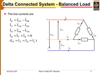
- 2. ELE101/102 Dept of E&E,MIT Manipal 2 Delta Connected System - Balanced Load R Y B Z Z Z YI ∧ BI ∧ RYV ∧ YBV ∧ BRV ∧ RYI ∧ YBI ∧ RI ∧ BRI ∧ )IIII( 0III III III III LBYR BYR YBBRB RYYBY BRRYR === =++ −= −= −= The line currents are
- 3. ELE101/102 Dept of E&E,MIT Manipal 3 B I ∧ RI ∧ YI ∧ BR I ∧ YB I ∧ − YB I ∧ RY I ∧ BR I ∧ − RY I ∧ − 1 2 0 ° 3 0 ° φ RYV ∧ YBV ∧ BRV ∧ Delta Connected – Balanced Load Complete phasor diagram:
- 4. ELE101/102 Dept of E&E,MIT Manipal 4 BI ∧ RI ∧ YI ∧ BRI ∧ YBI ∧ − YBI ∧ RYI ∧ BRI ∧ − RYI ∧ − 1 2 0 ° 3 0 ° Relation between The line & phase currents Delta Connected – Balanced Load phL phL o ph o ph o BR o RYR BRRYR I3I )(30cosI2I cos30Icos30I cos30Icos30I|I| III = °= −= −= −=
- 5. ELE101/102 Dept of E&E,MIT Manipal 5 )(sinIV3powerReactive )(cosIV3 )(cos 3 I V3 )(cosIVpowerActive LL LL L L phph φ= φ= φ= φ=3 Note: Φ is the phase angle between phase voltage and phase current Delta Connected – Balanced Load
- 6. ELE101/102 Dept of E&E,MIT Manipal 6 Three coils are connected in delta to a 3 Φ, 3 wire, 415 V, 50 Hz supply and take a line current of 5 A, 0.8 p.f lagging. a) Calculate the resistance and inductance of the coils. b) Draw the phasor diagram c) Find the active and reactive power Illustration VAR Ra Ans ph 2156Q2875W;P(c) H0.274L115;)( : TT == ==
- 7. ELE101/102 Dept of E&E,MIT Manipal 6 Three coils are connected in delta to a 3 Φ, 3 wire, 415 V, 50 Hz supply and take a line current of 5 A, 0.8 p.f lagging. a) Calculate the resistance and inductance of the coils. b) Draw the phasor diagram c) Find the active and reactive power Illustration VAR Ra Ans ph 2156Q2875W;P(c) H0.274L115;)( : TT == ==