Location via proxy:   [ UP ]  
[Report a bug]   [Manage cookies]                
SlideShare a Scribd company logo
METALURGI LAS
Tujuan:

• Lebih mengenal proses pengelasan dan efeknya
  pada material
• Untuk melihat strukturmikro dan hardness pada
  Heat Affected Zone (HAZ)
• Mengetahu cacat-cacat las, penyebab dan
  usaha penanggulanganya.
• Industrial radiography techniques
Definitions:

• Welding is the joining of multiple pieces of metal
  by the use of heat and or pressure. A union of
  the parts is created by fusion or recrystallization
  across the metal interface. Welding can involve
  the use of filler material, or it can involve no
  filler.
What commercial and technological
 importance does welding have?

• Provides a permanent joint
• Weld joint can be stronger than parent material
   – If the filler material has superior strength characteristics and proper
     techniques are used
• Usually the most economical way to join components
• Can be done in the field away from a factory
Limitations?
• Expensive in terms of labour cost
• Most welding processes involve the use high energy, are
  inherently dangerous
• Welds are permanent bonds, not allowing for convenient
  disassembly
• The welded joint can suffer from certain quality defects
  that are difficult to detect, these defects can reduce the
  quality of the joint
Types:


• Arc Welding
  – A fusion welding process in which the coalescence of the metals is
    achieved by the heat from an electric arc between an electrode
    and the work
• Shielded Metal Arc Welding (SMAW)
   – An arc welding process that uses a consumable electrode
     consisting of a filler metal rod coated with chemicals that
     provide flux and shielding
• Gas Metal Arc Welding (GMAW)
  – Arc welding process in which the electrode is a consumable bare
    metal wire and shielding is accomplished by flooding the area
    with gas
• Submerged Arc Welding
  – Arc welding process that uses a continuous, consumable bare
    wire electrode, arc shielding is provided by a cover of granular
    flux
• Resistance Welding
   – A fusion welding process that utilizes a combination of heat and
     pressure to accomplish coalescence, the heat being generated
     by electrical resistance to current flow at the junction to be
     welded
• Oxyacetylene Welding
  – A fusion welding process performed by a high-temperature flame
    from a combustion of acetylene and oxygen

                  C2 H 2 + O2 → 2CO + H 2 + HEAT
           2CO + H 2 + 1.5O2 → 2CO2 + H 2O + HEAT
Fusion Weld Joint


• Fusion Zone
  – A mixture of filler metal and base metal that has completely
    melted
  – High degree of homogeneity among the component metals that
    have been melted during welding
  – The mixing of these components is motivated largely by
    convection in the molten weld pool
• Weld Interface
   – The narrow boundary that separates the fusion zone and the
     heat affected zone
   – This interface consists of a thin band of base metal that was
     melted or partially melted (localized melting within the grains)
     during the welding process, but immediately solidified before any
     mixing could take place
• Heat Affected Zone (HAZ)
   – The metal in this region has experienced temperature below its
     melting point, but high enough to change the microstructure
   – This metal consists of the base metal which has undergone a
     heat treatment due to the welding temperatures, so that its
     properties have been altered.
   – The amount of metallurgical damage in the HAZ depends on the
     amount of heat input, peak temp reached, distance from fusion
     zone, time at elevated temp, cooling rate, and the metal’s
     thermal properties
• Heat Affected Zone (HAZ) cont’d
   – The effect on the mechanical properties is usually negative, and
     it is most often the region of the weld joint where failure occurs
• Unaffected Base Metal Zone
   – Where no metallurgical change has occurred
   – The base metal surrounding the HAZ is likely to be in a state of
     high residual stress, due to the shrinkage in the fusion zone
Weld Defects:
1. Cracks
  Detection
     Surface: Visual examination, magnetic particle, dye or
              fluorescent penetrant inspection

     Internal: Ultrasonic flaw detection, radiography
Solidification Cracking
• Causes:
  – Large depth/width ratio of weld
    bead
  – High arc energy and/or preheat
  – Sulphur, phosphorus or niobium
    pick-up from parent metal
Hydrogen Induced HAZ Cracking
• Causes:
  – Hardened HAZ coupled with the
    presence of hydrogen diffused from
    weld metal
  – Susceptibility increases with the
    increasing thickness of section
    especially in steels with high carbon
    equivalent composition
  – Can also occur in weld metal
  – Increase welding heat beneficial
  – Preheating sometimes necessary
  – Control of moisture in consumables
    and cleanliness of weld prep
    desirable
Lamellar Tearing
• Causes:
  – Poor ductility in through-thickness
    direction in rolled plate due to non-
    metallic inclusions
  – Occurs mainly in joints having weld
    metal deposited on plate surfaces
  – Prior buttering of surface beneficial
    for susceptible plate
Reheat Cracking
• Occurs in creep resisting and some
  thick section structural low alloy steels
  during post weld heat treatment
• Causes:
    – Poor creep ductility in HAZ
      coupled with thermal stress
    – Accentuated by severe notches           X 35

      such as preexisting cracks, or
      tears at weld toes, or unfused root
      of partial penetration weld
    – Heat treatment may need to
      include low temperature soaking
    – Grinding or peening weld toes
      after welding can be beneficial


                                               X 200
2. Cavities
  Detection
     Surface: Visual inspection

     Internal: Ultrasonic flaw detection, radiography
Worm Holes
• Resulting from the entrapment of gas
  between the solidifying dendrites of
  weld metal, often showing ‘herringbone’
  array ( B )
• Causes:
   – The gas may arise from
     contamination of surfaces to be
     welded, or be prevented from
     escaping from beneath the weld by
     joint crevices
Uniformly Distributed Porosity
 • Resulting from the entrapment of gas
   in solidified weld metal
 • Causes:
    – Gas may originate from dampness
      or grease on consumables or
      workpiece, or by nitrogen
      contamination from the
      atmosphere
    – If the weld wire used contains
      insufficient deoxidant it is also
      possible for carbon monoxide to
      cause porosity
Restart Porosity
• Causes:
  – Unstable arc conditions at weld
    start, where weld pool protection
    may be incomplete and temperature
    gradients have not had time to
    equilibrate, coupled with inadequate
    manipulative technique to allow for
    this instability
Surface Porosity
• Causes:
  – Excessive contamination from
    grease, dampness, or atmosphere
    entrainment
  – Occasionally caused by excessive
    sulphur in consumables or parent
    metal
Crater Pipes
• Resulting from shrinkage at the end
  crater of a weld run
• Causes:
   – Incorrect manipulative technique or
     current decay to allow for crater
     shrinkage
3. Solid Inclusions
   Detection
    - normally revealed by radiography


Linear Slag Inclusions
• Cause:
    – Incomplete removal of slag
      in multi-pass welds often
      associated with the
      presence of undercut or
      irregular surfaces in
      underlying passes
Isolated Slag Inclusions
 • Causes:
    – Normally by the presence of mill
      scale and/or rust on prepared
      surfaces, or electrodes with
      cracked or damaged coverings
    – Can also arise from isolated
      undercut in underlying passes of
      multi-pass welds
4. Lack of Fusion and Penetration

    Detection
         –   This type of defect tends to be sub surface and is therefore
             detectable only by ultrasonics or X-ray methods
         –   Lack of side wall fusion which penetrates the surface may be
             detected using magnetic particle, dye or fluorescent
             penetrant inspection


    Cause
         –   Incorrect weld conditions (eg. low current) and/or incorrect
             weld preparation (eg. root face too large)
         –   Both cause the weld pool to freeze too rapidly
Lack of side-wall fusion   Lack of root fusion    Lack of inter-run fusion


                            Lack of penetration
5. Imperfect Shape
   Detection
    - all shape defects can be determined by visual inspections


Linear Misalignment
• Cause:
    – Incorrect assembly or
      distortion during fabrication
Excessive Reinforcement
• Causes:
  – Deposition of too much weld metal,
    often associated with in adequate
    weld preparation
  – Incorrect welding parameters
  – Too large of an electrode for the
    joint in question
Overlap
• Causes:
  – Poor manipulative technique
  – Too cold a welding conditions
    (current and voltage too low)
Undercut
• Results from the washing away of edge
  preparation when molten
• Causes:
   – Poor welding technique
   – Imbalance in welding conditions
Excessive Penetration
 • Causes:
   – Incorrect edge preparation
     providing insufficient support
     at the weld root
   – Incorrect welding conditions
     (too high of current)
   – The provision of a backing bar
     can alleviate this problem in
     difficult circumstances
Root Concavity
 • Causes:
   – Shrinkage of molten pool at
     weld root, due to incorrect root
     preparation or too cold of
     conditions
   – May also be caused by
     incorrect welding technique
5. Miscellaneous Faults

Arc Strikes
• Cause:
    – Accidental contact of an
      electrode or welding torch
      with a plate surface remote
      from the weld
    – Usually result in small hard
      spots just beneath the
      surface which may contain
      cracks, and are thus to be
      avoided
Spatter
• Causes:
  – Incorrect welding conditions
    and/or contaminated
    consumables or preparations,
    giving rise to explosions within
    the arc and weld pool
  – Globules of molten metal are
    thrown out, and adhere to the
    parent metal remote from the
    weld
Copper Pick-Up
• Causes:
  – Melting of copper contact tube in
    MIG welding due to incorrect
    welding conditions


                                        X 275
PROCEDURE
1. Students are provided with weldments of approximately 0.4% C
   steel. The first weldment was prepared without preheat treatment.
   The electrode used produces a large amount of hydrogen which
   diffuses into the weld metal. The second was preheated to 150˚C.
   An electrode with relatively low hydrogen content was used. For
   each of these samples:

    a) Examine the microstructure of the weldments in a traverse from weld
       metal to parent metal, sketching about five different areas. Using the
       Fe-C diagram and your knowledge of the phase transformations in
       steel, comment on the microstructures describing the time-temperature
       history and how this history resulted in the observed structure.
    b) Conduct a microhardness traverse across the HAZ and correlate the
       hardness with the microstructure observed in (a).

2. Some radiographs of weld defects are provided. Examine these
   radiographs and describe the defects responsible, citing ways of
   avoiding the problem.
Radiographs
 ID #   Position                  Comments                         Results     Page


                                                                               1
 Q13      1gf            Shallow undercut by cap pass             Acceptable
 Q18      4gf             Incompletefusion at the root               Fail
 Q10      1gf             Incompletefusion at the root               Fail


                                                                               2
  H2      4gf    Incompletefusion at the root & slag throughout      Fail
  H1      1gf                 Porosity throughout                    Fail
   J3     4gf                   Slag inclusions                   Acceptable


                                                                               3
 F10      1gf                   Slag inclusions                      Fail
  F2      2g              Incompletefusion at the root               Fail
  F7      3gf                      Minor slag                     Acceptable


                                                                               4
  983     2g                    Slag inclusions                   Acceptable
  983     3gf      Slag inclusions at the root & inner passes        Fail
  982     3gf                   Slag inclusions                      Fail


                                                                               5
  852     2g                       No defects                     Acceptable
  852     3gf         Slag inclusion at the root & porosity          Fail
  850     4gf               Minor slag & film scratch             Acceptable

More Related Content

Me 328 welding metallurgy

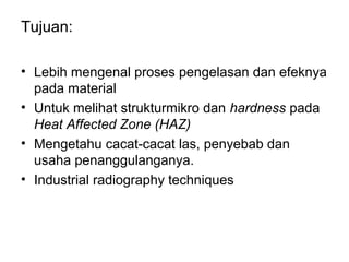
  • 2. Tujuan: • Lebih mengenal proses pengelasan dan efeknya pada material • Untuk melihat strukturmikro dan hardness pada Heat Affected Zone (HAZ) • Mengetahu cacat-cacat las, penyebab dan usaha penanggulanganya. • Industrial radiography techniques
  • 3. Definitions: • Welding is the joining of multiple pieces of metal by the use of heat and or pressure. A union of the parts is created by fusion or recrystallization across the metal interface. Welding can involve the use of filler material, or it can involve no filler.
  • 4. What commercial and technological importance does welding have? • Provides a permanent joint • Weld joint can be stronger than parent material – If the filler material has superior strength characteristics and proper techniques are used • Usually the most economical way to join components • Can be done in the field away from a factory
  • 5. Limitations? • Expensive in terms of labour cost • Most welding processes involve the use high energy, are inherently dangerous • Welds are permanent bonds, not allowing for convenient disassembly • The welded joint can suffer from certain quality defects that are difficult to detect, these defects can reduce the quality of the joint
  • 6. Types: • Arc Welding – A fusion welding process in which the coalescence of the metals is achieved by the heat from an electric arc between an electrode and the work
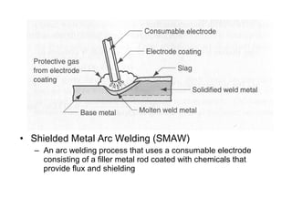
  • 7. • Shielded Metal Arc Welding (SMAW) – An arc welding process that uses a consumable electrode consisting of a filler metal rod coated with chemicals that provide flux and shielding
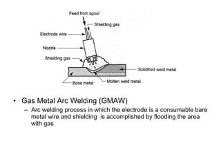
  • 8. • Gas Metal Arc Welding (GMAW) – Arc welding process in which the electrode is a consumable bare metal wire and shielding is accomplished by flooding the area with gas
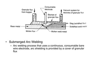
  • 9. • Submerged Arc Welding – Arc welding process that uses a continuous, consumable bare wire electrode, arc shielding is provided by a cover of granular flux
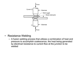
  • 10. • Resistance Welding – A fusion welding process that utilizes a combination of heat and pressure to accomplish coalescence, the heat being generated by electrical resistance to current flow at the junction to be welded
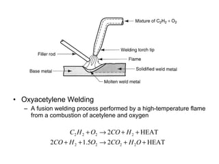
  • 11. • Oxyacetylene Welding – A fusion welding process performed by a high-temperature flame from a combustion of acetylene and oxygen C2 H 2 + O2 → 2CO + H 2 + HEAT 2CO + H 2 + 1.5O2 → 2CO2 + H 2O + HEAT
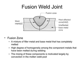
  • 12. Fusion Weld Joint • Fusion Zone – A mixture of filler metal and base metal that has completely melted – High degree of homogeneity among the component metals that have been melted during welding – The mixing of these components is motivated largely by convection in the molten weld pool
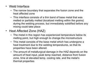
  • 13. • Weld Interface – The narrow boundary that separates the fusion zone and the heat affected zone – This interface consists of a thin band of base metal that was melted or partially melted (localized melting within the grains) during the welding process, but immediately solidified before any mixing could take place • Heat Affected Zone (HAZ) – The metal in this region has experienced temperature below its melting point, but high enough to change the microstructure – This metal consists of the base metal which has undergone a heat treatment due to the welding temperatures, so that its properties have been altered. – The amount of metallurgical damage in the HAZ depends on the amount of heat input, peak temp reached, distance from fusion zone, time at elevated temp, cooling rate, and the metal’s thermal properties
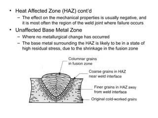
  • 14. • Heat Affected Zone (HAZ) cont’d – The effect on the mechanical properties is usually negative, and it is most often the region of the weld joint where failure occurs • Unaffected Base Metal Zone – Where no metallurgical change has occurred – The base metal surrounding the HAZ is likely to be in a state of high residual stress, due to the shrinkage in the fusion zone
  • 15. Weld Defects: 1. Cracks Detection Surface: Visual examination, magnetic particle, dye or fluorescent penetrant inspection Internal: Ultrasonic flaw detection, radiography
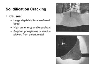
  • 16. Solidification Cracking • Causes: – Large depth/width ratio of weld bead – High arc energy and/or preheat – Sulphur, phosphorus or niobium pick-up from parent metal
  • 17. Hydrogen Induced HAZ Cracking • Causes: – Hardened HAZ coupled with the presence of hydrogen diffused from weld metal – Susceptibility increases with the increasing thickness of section especially in steels with high carbon equivalent composition – Can also occur in weld metal – Increase welding heat beneficial – Preheating sometimes necessary – Control of moisture in consumables and cleanliness of weld prep desirable
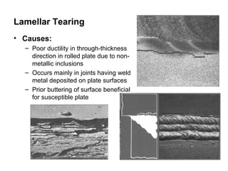
  • 18. Lamellar Tearing • Causes: – Poor ductility in through-thickness direction in rolled plate due to non- metallic inclusions – Occurs mainly in joints having weld metal deposited on plate surfaces – Prior buttering of surface beneficial for susceptible plate
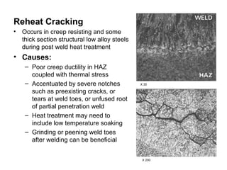
  • 19. Reheat Cracking • Occurs in creep resisting and some thick section structural low alloy steels during post weld heat treatment • Causes: – Poor creep ductility in HAZ coupled with thermal stress – Accentuated by severe notches X 35 such as preexisting cracks, or tears at weld toes, or unfused root of partial penetration weld – Heat treatment may need to include low temperature soaking – Grinding or peening weld toes after welding can be beneficial X 200
  • 20. 2. Cavities Detection Surface: Visual inspection Internal: Ultrasonic flaw detection, radiography
  • 21. Worm Holes • Resulting from the entrapment of gas between the solidifying dendrites of weld metal, often showing ‘herringbone’ array ( B ) • Causes: – The gas may arise from contamination of surfaces to be welded, or be prevented from escaping from beneath the weld by joint crevices
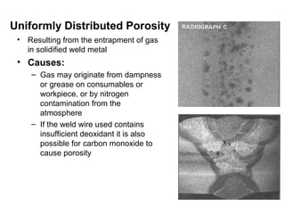
  • 22. Uniformly Distributed Porosity • Resulting from the entrapment of gas in solidified weld metal • Causes: – Gas may originate from dampness or grease on consumables or workpiece, or by nitrogen contamination from the atmosphere – If the weld wire used contains insufficient deoxidant it is also possible for carbon monoxide to cause porosity
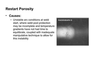
  • 23. Restart Porosity • Causes: – Unstable arc conditions at weld start, where weld pool protection may be incomplete and temperature gradients have not had time to equilibrate, coupled with inadequate manipulative technique to allow for this instability
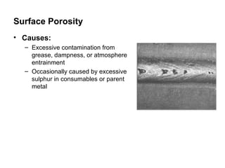
  • 24. Surface Porosity • Causes: – Excessive contamination from grease, dampness, or atmosphere entrainment – Occasionally caused by excessive sulphur in consumables or parent metal
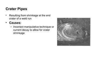
  • 25. Crater Pipes • Resulting from shrinkage at the end crater of a weld run • Causes: – Incorrect manipulative technique or current decay to allow for crater shrinkage
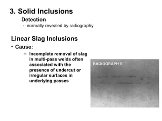
  • 26. 3. Solid Inclusions Detection - normally revealed by radiography Linear Slag Inclusions • Cause: – Incomplete removal of slag in multi-pass welds often associated with the presence of undercut or irregular surfaces in underlying passes
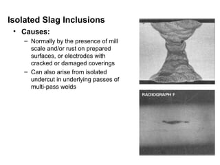
  • 27. Isolated Slag Inclusions • Causes: – Normally by the presence of mill scale and/or rust on prepared surfaces, or electrodes with cracked or damaged coverings – Can also arise from isolated undercut in underlying passes of multi-pass welds
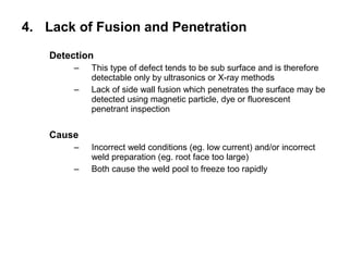
  • 28. 4. Lack of Fusion and Penetration Detection – This type of defect tends to be sub surface and is therefore detectable only by ultrasonics or X-ray methods – Lack of side wall fusion which penetrates the surface may be detected using magnetic particle, dye or fluorescent penetrant inspection Cause – Incorrect weld conditions (eg. low current) and/or incorrect weld preparation (eg. root face too large) – Both cause the weld pool to freeze too rapidly
  • 29. Lack of side-wall fusion Lack of root fusion Lack of inter-run fusion Lack of penetration
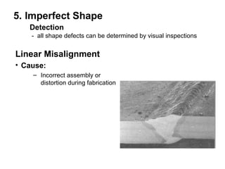
  • 30. 5. Imperfect Shape Detection - all shape defects can be determined by visual inspections Linear Misalignment • Cause: – Incorrect assembly or distortion during fabrication
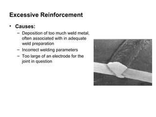
  • 31. Excessive Reinforcement • Causes: – Deposition of too much weld metal, often associated with in adequate weld preparation – Incorrect welding parameters – Too large of an electrode for the joint in question
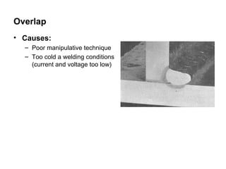
  • 32. Overlap • Causes: – Poor manipulative technique – Too cold a welding conditions (current and voltage too low)
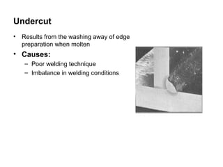
  • 33. Undercut • Results from the washing away of edge preparation when molten • Causes: – Poor welding technique – Imbalance in welding conditions
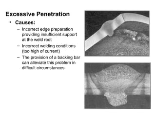
  • 34. Excessive Penetration • Causes: – Incorrect edge preparation providing insufficient support at the weld root – Incorrect welding conditions (too high of current) – The provision of a backing bar can alleviate this problem in difficult circumstances
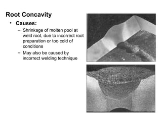
  • 35. Root Concavity • Causes: – Shrinkage of molten pool at weld root, due to incorrect root preparation or too cold of conditions – May also be caused by incorrect welding technique
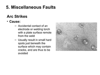
  • 36. 5. Miscellaneous Faults Arc Strikes • Cause: – Accidental contact of an electrode or welding torch with a plate surface remote from the weld – Usually result in small hard spots just beneath the surface which may contain cracks, and are thus to be avoided
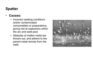
  • 37. Spatter • Causes: – Incorrect welding conditions and/or contaminated consumables or preparations, giving rise to explosions within the arc and weld pool – Globules of molten metal are thrown out, and adhere to the parent metal remote from the weld
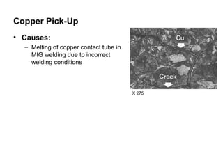
  • 38. Copper Pick-Up • Causes: – Melting of copper contact tube in MIG welding due to incorrect welding conditions X 275
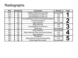
  • 39. PROCEDURE 1. Students are provided with weldments of approximately 0.4% C steel. The first weldment was prepared without preheat treatment. The electrode used produces a large amount of hydrogen which diffuses into the weld metal. The second was preheated to 150˚C. An electrode with relatively low hydrogen content was used. For each of these samples: a) Examine the microstructure of the weldments in a traverse from weld metal to parent metal, sketching about five different areas. Using the Fe-C diagram and your knowledge of the phase transformations in steel, comment on the microstructures describing the time-temperature history and how this history resulted in the observed structure. b) Conduct a microhardness traverse across the HAZ and correlate the hardness with the microstructure observed in (a). 2. Some radiographs of weld defects are provided. Examine these radiographs and describe the defects responsible, citing ways of avoiding the problem.
  • 40. Radiographs ID # Position Comments Results Page 1 Q13 1gf Shallow undercut by cap pass Acceptable Q18 4gf Incompletefusion at the root Fail Q10 1gf Incompletefusion at the root Fail 2 H2 4gf Incompletefusion at the root & slag throughout Fail H1 1gf Porosity throughout Fail J3 4gf Slag inclusions Acceptable 3 F10 1gf Slag inclusions Fail F2 2g Incompletefusion at the root Fail F7 3gf Minor slag Acceptable 4 983 2g Slag inclusions Acceptable 983 3gf Slag inclusions at the root & inner passes Fail 982 3gf Slag inclusions Fail 5 852 2g No defects Acceptable 852 3gf Slag inclusion at the root & porosity Fail 850 4gf Minor slag & film scratch Acceptable