


Minor losses elbow
- 1. Erbil Polytechnic University Koya Technical Institute Petroleum Technology Operation and Control Report Fluid Mechanic Lab. Test no: (9) Test name: (Minor Losses) Supervised by: Karwan A. Ali Date of Test: 05/04/2018 Date of Submit: 03/05/2018 Prepared by: Muhammed Fuad Rashid
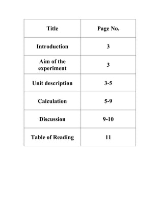
- 2. Title Page No. Introduction 3 Aim of the experiment 3 Unit description 3-5 Calculation 5-9 Discussion 9-10 Table of Reading 11
- 3. Introduction: Pipe system which include valves, elbows (Bends), enlargements, contractions, inlets, outlets, and other fittings that cause additional losses, each of these devices causes a change in the magnitude or the direction of the velocity vectors and hence results 1n a loss. A minor loss is expressed in terms of a loss coefficient (K), defined by: 𝑉2 2𝑔 =eH In this experiment we will calculate the minor losses due special pipe component such as pipe bends or elbows, pipe branches, changes in cross-section, valves, and flaps -Aim of experiment: Calculating the loss coefficient (K) for pipe bends or elbows, pipe branches, changes in cross-section, valves, and flaps. -Unit description: The unit as shown in the figure consists of a square tubular steel frame with a Powder-‘coated back wall, on which a, pipe system is mounted with sections which can be. Individually shut off. The back wall also features two level-tube pressure gauges attached using star- type nuts. The gauges can be fitted in two positions on the back Wall. Various Measurement objects can be accommodated in an adjustable Measurement system“ Water is supplied either-by way of the HM 150 Hydraulics Bench or via the laboratory mains. The HM 150 permits construction of closed water Circuit. -gauge:PressureDouble
- 4. -The double pressure gauge is suitable for measuring both differential pressures and gauge pressures in mm w.g.; these can then be converted into absolute pressures with allowance for the atmospheric pressure. -The measuring range is O-1000mm w.g. -The gauge consists of two glass level tubes backed by a metal mm scale. -The two level tubes are interconnected at the top and have a joint vent valve. -Differential pressure is measured with the vent valve closed and gauge pressure with the valve open. -The measurement points are connected to the lower end of the Level tubes using rapid-action hose couplings with automatic shut-off. -A drain valve 13 provided at the bottom of each level tube. -of experiment:Performance *The following instructions for experimentation and the performance of the experiments A, B are based on the HM 150 Hydraulics Bench. Position test set-up on the HM 150 Hydraulics Bench with drainage via volumetric tank. * Loosen star-type nuts for pressure gauge attachment on back of unit and move gauges down a hole. Then retighten nuts * Make hose connection between HM 150 and unit. *Open drain of HM 150. * Switch on pump and slowly open main coke of HM 150. * Connect pressure gauges to desired measurement points. * Slowly Open ball cock of appropriate measurement system and vent pressure gauges; see Section of double pressure gauge. * By simultaneously adjusting vent and drain valve on pressure gauge, set water level such that both water columns are in the measuring range.
- 5. *Determine volumetric flow. To do so, establish time t required to raise the level in the volumetric tank of the HM 150 from 10 to 20 or 30 litters. The drain cock beneath the tank is to be closed for this purpose. -Pipe elbow experiment: For pipe elbows, the loss coefficient (K) depends on the angle of deviation of the flow and the ratio of the elbow radius to the pipe diameter. In addition, the coefficient of resistance is influenced by the shape of the elbow. For this special case of a pipe elbow with 90° deviation, the following diagram is applicable for smooth and rough pipes. For pipe angles, i. e Elbow radii less than the pipe diameter (R/d<1) the losses coefficients for knee pieces are approximately applicable. For example, for a 90° knee piece / kink, with a smooth pipe, the K is 1.13 and for rough pipes the K 18 1. 68, while for a 45 piece = 0.36.rough=.0.24 and KsmoothK
- 6. -Table of reading: Time second Volume liter Qrotameter Valve Pipe elbow No. Elbow single 45 ̊ Double elbow 90 ̊ Single elbow 90 ̊ Δh (cm)Δh (cm)Δh (cm) 19.84511901.87.74.21 16.2514001.510.452 14.86515203.61263 -Calculation: Volume=5 L → 5000cm3 g=981cm/s2 d=20mm→0.2cm A=3.14cm2 A/single elbow: t=19.84sΔh=4.2cmNo.1: s3 cm 𝑣𝑜𝑙𝑢𝑚𝑒 𝑡𝑖𝑚𝑒 = 5000 19.84 = 252.016=1Q V1= 𝑄 𝐴 = 252.016 3.14 = 80.26cms K1= 2𝑔∆ℎ 𝑉2 = 2×981×4.2 80.262 =1.217 cm4.2=𝐾 𝑉2 2𝑔 → 2𝑔∆ℎ 𝑉2 × 𝑉2 2𝑔 = ∆ℎ=e1h t=16.2sΔh=5cmNo.2: s3 cm 𝑣𝑜𝑙𝑢𝑚𝑒 𝑡𝑖𝑚𝑒 = 5000 16.2 = 308.641=2Q
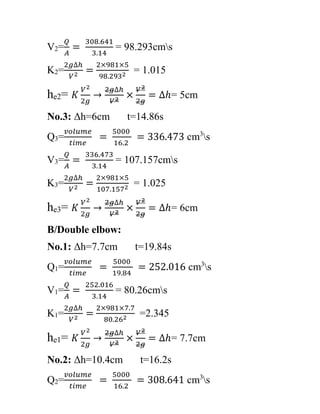
- 7. V2= 𝑄 𝐴 = 308.641 3.14 = 98.293cms K2= 2𝑔∆ℎ 𝑉2 = 2×981×5 98.2932 = 1.015 = 5cm𝐾 𝑉2 2𝑔 → 2𝑔∆ℎ 𝑉2 × 𝑉2 2𝑔 = ∆ℎ=e2h s4.86t=1Δh=6cmNo.3: s3 cm 𝑣𝑜𝑙𝑢𝑚𝑒 𝑡𝑖𝑚𝑒 = 5000 16.2 = 336.473=3Q V3= 𝑄 𝐴 = 336.473 3.14 = 107.157cms K3= 2𝑔∆ℎ 𝑉2 = 2×981×5 107.1572 = 1.025 cm6=𝐾 𝑉2 2𝑔 → 2𝑔∆ℎ 𝑉2 × 𝑉2 2𝑔 = ∆ℎ=e3h B/Double elbow: t=19.84sΔh=7.7cmNo.1: s3 cm 𝑣𝑜𝑙𝑢𝑚𝑒 𝑡𝑖𝑚𝑒 = 5000 19.84 = 252.016=1Q V1= 𝑄 𝐴 = 252.016 3.14 = 80.26cms K1= 2𝑔∆ℎ 𝑉2 = 2×981×7.7 80.262 =2.345 cm7.7=𝐾 𝑉2 2𝑔 → 2𝑔∆ℎ 𝑉2 × 𝑉2 2𝑔 = ∆ℎ=e1h t=16.2sΔh=10.4cmNo.2: s3 cm 𝑣𝑜𝑙𝑢𝑚𝑒 𝑡𝑖𝑚𝑒 = 5000 16.2 = 308.641=2Q
- 8. V2= 𝑄 𝐴 = 308.641 3.14 = 98.293cms K2= 2𝑔∆ℎ 𝑉2 = 2×981×10.4 98.2932 = 2.112 cm10.4=𝐾 𝑉2 2𝑔 → 2𝑔∆ℎ 𝑉2 × 𝑉2 2𝑔 = ∆ℎ=e2h t=14.86sΔh=12cmNo.3: s3 cm 𝑣𝑜𝑙𝑢𝑚𝑒 𝑡𝑖𝑚𝑒 = 5000 16.2 = 336.473=3Q V3= 𝑄 𝐴 = 336.473 3.14 = 107.157cms K3= 2𝑔∆ℎ 𝑉2 = 2×981×12 107.1572 = 2.050 cm12=𝐾 𝑉2 2𝑔 → 2𝑔∆ℎ 𝑉2 × 𝑉2 2𝑔 = ∆ℎ=e3h C/Elbow Angle 45 ̊ : t=19.84scmΔh=1.8No.1: s3 cm 𝑣𝑜𝑙𝑢𝑚𝑒 𝑡𝑖𝑚𝑒 = 5000 19.84 = 252.016=1Q V1= 𝑄 𝐴 = 252.016 3.14 = 80.26cms K1= 2𝑔∆ℎ 𝑉2 = 2×981×1.8 80.262 =0.548 cm1.8=𝐾 𝑉2 2𝑔 → 2𝑔∆ℎ 𝑉2 × 𝑉2 2𝑔 = ∆ℎ=e1h t=16.2scm2.5Δh=No.2: s3 cm 𝑣𝑜𝑙𝑢𝑚𝑒 𝑡𝑖𝑚𝑒 = 5000 16.2 = 308.641=2Q
- 9. V2= 𝑄 𝐴 = 308.641 3.14 = 98.293cms K2= 2𝑔∆ℎ 𝑉2 = 2×981×2.5 98.2932 = 0.507 5cm2.=𝐾 𝑉2 2𝑔 → 2𝑔∆ℎ 𝑉2 × 𝑉2 2𝑔 = ∆ℎ=e2h t=14.86s6cm3.Δh=No.3: s3 cm 𝑣𝑜𝑙𝑢𝑚𝑒 𝑡𝑖𝑚𝑒 = 5000 16.2 = 336.473=3Q V3= 𝑄 𝐴 = 336.473 3.14 = 107.157cms K3= 2𝑔∆ℎ 𝑉2 = 2×981×3.6 107.1572 = 0.615 6cm3.=𝐾 𝑉2 2𝑔 → 2𝑔∆ℎ 𝑉2 × 𝑉2 2𝑔 = ∆ℎ=e3h Table of Calculation: V (cm/s) Pipe elbow No. Elbow Angle 45 ̊Double elbow 90 ̊Single elbow 90 ̊ he (cm) K Δh (cm) he (cm) K Δh (cm) he (cm) K Δh (cm) 80.261.80.5481.87.72.3457.74.21.2174.21 98.2932.50.5072.510.42.11210.451.01552 107.1573.60.6153.6122.0501261.02563 -Discussion: * Which elbow has minimum loss coefficient and why? A/ The Elbow Angle has minimum loss coefficient because it’s less friction
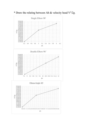
- 10. ./2g2 * Draw the relating between Ah & velocity head V 3159638 3344638 3529638 3714638 3899638 4084638 4269638 4454638 4639638 4824638 5009638 5194638 5379638 5564638 5749638 5934638 4.2 4.4 4.6 4.8 5 5.2 5.4 5.6 5.8 6 6.2 V2/2g Δh Single Elbow 90̊ 3159638 3344638 3529638 3714638 3899638 4084638 4269638 4454638 4639638 4824638 5009638 5194638 5379638 5564638 5749638 5934638 7.6 8 8.4 8.8 9.2 9.6 10 10.4 10.8 11.2 11.6 12 V2/2g Δh Double Elbow 90 ̊ 3159638 3344638 3529638 3714638 3899638 4084638 4269638 4454638 4639638 4824638 5009638 5194638 5379638 5564638 5749638 5934638 1.8 1.9 2 2.1 2.2 2.3 2.4 2.5 2.6 2.7 2.8 2.9 3 3.1 3.2 3.3 3.4 3.5 3.6 V2/2g Δh Elbow Angle 45̊