


M.S.ThesisDefense
- 1. Electrophoretic Deposition of Cobalt Ferrite Nanoparticles into 3D Felt Nicole Shellhammer Pacheco M.S. Thesis Defense Chemical Engineering Committee Members: Professor Jan B. Talbot, Chair Professor Joanna M. McKittrick Professor Justin P. Opatkiewicz 1
- 2. • Motivation and Objectives • Background • Experiments – Electrophoretic Deposition (EPD) – Adhesion Tests – EPD Penetration – Electrochemical Study • Results & Discussion • Conclusions Outline Image Source: http://www.aliexpress.com/item/Graphite-felt-custom-made-for-vacuum- furnace-Insulation-protection/32398127261.html 2
- 3. Hydrogen as a fuel • Uses of hydrogen – Burning hydrogen – Hydrogen fuel cells • Advantages of hydrogen as a fuel – Safe – Environmentally-friendly – Can replace fossil fuels used in transportation systems • Challenge: 86 % of hydrogen is produced from burning fossil fuels1 Motivation and Objectives 1Steinfeld, A. International Journal of Hydrogen Energy 2002, 27, 611–619. Image source: http://www.zmescience.com/science/hydrogen-car-fuel-04042013/ 3
- 4. Objective • Produce hydrogen from clean and sustainable method – Solar sulfur-ammonia (SA) thermochemical cycle Goals • Penetrate and coat nanoparticles into 3D felt with EPD • Improve kinetically slow anodic reaction for SA cycle with EPD deposits of electrocatalysts – Determine EPD conditions and suspension properties Motivation and Objectives Image source: http://www.baseofengineering.com/index.php/2015/06/12/engineers-develop- state-by-state-plan-to-convert-us-to-100-clean-renewable-energy-by-2050/ 4
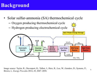
- 5. Background • Solar sulfur-ammonia (SA) thermochemical cycle – Oxygen producing thermochemical cycle – Hydrogen producing electrochemical cycle Image source: Taylor, R.; Davenport, R.; Talbot, J.; Herz, R.; Luc, W.; Genders, D.; Symons, P.; Brown, L. Energy Procedia 2014, 49, 2047–2058. 5
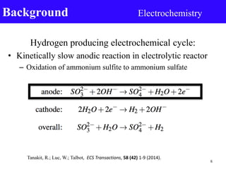
- 6. Hydrogen producing electrochemical cycle: • Kinetically slow anodic reaction in electrolytic reactor – Oxidation of ammonium sulfite to ammonium sulfate Background Electrochemistry Tanakit, R.; Luc, W.; Talbot, ECS Transactions, 58 (42) 1-9 (2014). 6
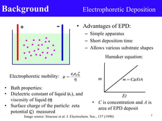
- 7. • Advantages of EPD: – Simple apparatus – Short deposition time – Allows various substrate shapes Background Electrophoretic Deposition Image source: Siracuse et al. J. Electrochem. Soc., 137 (1990) Hamaker equation: m Et Electrophoretic mobility: 7 • Bath properties: • Dielectric constant of liquid ( ), and viscosity of liquid ( ) • Surface charge of the particle: zeta potential ( ) measured • C is concentration and A is area of EPD deposit
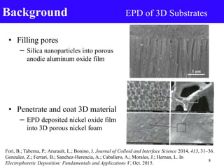
- 8. • Filling pores – Silica nanoparticles into porous anodic aluminum oxide film • Penetrate and coat 3D material – EPD deposited nickel oxide film into 3D porous nickel foam Background EPD of 3D Substrates Fori, B.; Taberna, P.; Arurault, L.; Bonino, J. Journal of Colloid and Interface Science 2014, 413, 31–36. Gonzalez, Z.; Ferrari, B.; Sanchez-Herencia, A.; Caballero, A.; Morales, J.; Hernan, L. In Electrophoretic Deposition: Fundamentals and Applications V, Oct. 2015. 8
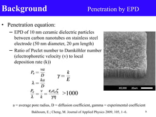
- 9. • Penetration equation: – EPD of 10 nm ceramic dielectric particles between carbon nanotubes on stainless steel electrode (50 nm diameter, 20 µm length) – Ratio of Peclet number to Damköhler number (electrophoretic velocity (v) to local deposition rate (k)) Background Penetration by EPD >1000 Bakhoum, E.; Cheng, M. Journal of Applied Physics 2009, 105, 1–6. 9 a = average pore radius, D = diffusion coefficient, gamma = experimental coefficient
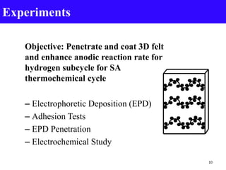
- 10. Objective: Penetrate and coat 3D felt and enhance anodic reaction rate for hydrogen subcycle for SA thermochemical cycle – Electrophoretic Deposition (EPD) – Adhesion Tests – EPD Penetration – Electrochemical Study Experiments 10
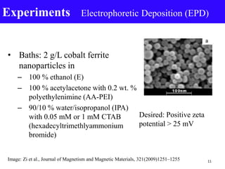
- 11. • Baths: 2 g/L cobalt ferrite nanoparticles in – 100 % ethanol (E) – 100 % acetylacetone with 0.2 wt. % polyethylenimine (AA-PEI) – 90/10 % water/isopropanol (IPA) with 0.05 mM or 1 mM CTAB (hexadecyltrimethlyammonium bromide) Experiments Electrophoretic Deposition (EPD) 11 Desired: Positive zeta potential > 25 mV Image: Zi et al., Journal of Magnetism and Magnetic Materials, 321(2009)1251–1255
- 12. • Substrates: – 3.14 cm2 of aluminum foil and graphite paper – 1 cm2 of 3 mm carbon, 6 mm graphite felt • E bath EPD conditions: – 20 V - 63 V for 1 or 2 min • AA-PEI bath EPD conditions: – 60 V - 128 V for 1-13 min Experiments Electrophoretic Deposition (EPD) 12
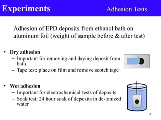
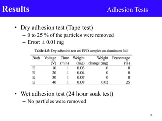
- 13. • Dry adhesion – Important for removing and drying deposit from bath – Tape test: place on film and remove scotch tape • Wet adhesion – Important for electrochemical tests of deposits – Soak test: 24 hour soak of deposits in de-ionized water Experiments Adhesion Tests 13 Adhesion of EPD deposits from ethanol bath on aluminum foil (weight of sample before & after test)
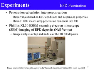
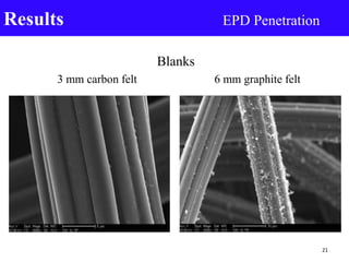
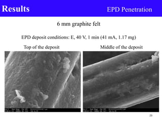
- 14. • Penetration calculation into porous carbon – Ratio values based on EPD conditions and suspension properties – Ratio > 1000 means deep penetration can occur into felt • Phillips XL30 ESEM scanning electron microscope (SEM) imaging of EPD deposits (Neil Verma) – Image analysis of top and middle of the 3D felt deposits Experiments EPD Penetration Image source: http://sirius.mtm.kuleuven.be/Research/Equipment/fiches/xl30-esem-feg.html 14
- 15. • Linear sweep voltammetry of EPD deposits – Oxidation of 2 M ammonium sulfite to ammonium sulfate – Deposits soaked in 2 M ammonium sulfite before (24 or 72 hr) – Princeton Applied Research VersaSTAT 3 potentiostat • Scanned from 0.0 to 1.0 V vs. standard calomel electrode (SCE) • Sweep rate of 50 mV/s • Standard three-compartment electrode cell Experiments Electrochemical Study 15 Image source: http://electronicstructure.wikidot.com/oxygen-reduction-reaction- on-platinum-using-dft 8 cm2 graphite cloth 1 cm2 deposit on 3 mm or 6 mm felt Standard calomel electrode (SCE)
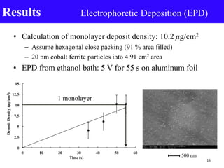
- 16. • Calculation of monolayer deposit density: 10.2 μg/cm2 – Assume hexagonal close packing (91 % area filled) – 20 nm cobalt ferrite particles into 4.91 cm2 area • EPD from ethanol bath: 5 V for 55 s on aluminum foil Results Electrophoretic Deposition (EPD) 0 2.5 5 7.5 10 12.5 15 0 10 20 30 40 50 60 DepositDensity(µg/cm2) Time (s) 1 monolayer 16 500 nm
- 17. • Dry adhesion test (Tape test) – 0 to 25 % of the particles were removed – Error: ± 0.01 mg • Wet adhesion test (24 hour soak test) – No particles were removed Results Adhesion Tests 17
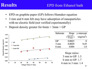
- 18. • EPD on graphite paper (GP) follows Hamaker equation • 3 mm and 6 mm felt may have adsorption of nanoparticles with no electric field (not verified experimentally) • Deposit density greater for 6mm > 3mm > GP Results EPD from Ethanol bath 0.00 0.20 0.40 0.60 0.80 1.00 1.20 1.40 0 10 20 30 40 50 60 70 DepsoitDensity(mg/cm2) Voltage*Time (V*min) GP 3 mm felt 6 mm felt Slope ratios: 3 mm to GP: 1.3 6 mm to GP: 1.7 6 mm to 3 mm: 1.4 18
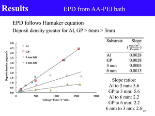
- 19. EPD follows Hamaker equation Deposit density greater for Al, GP > 6mm > 3mm Results EPD from AA-PEI bath Slope ratios: Al to 3 mm: 5.6 GP to 3 mm: 5.6 Al to 6 mm: 2.2 GP to 6 mm: 2.2 6 mm to 3 mm: 2.6 0.0 0.5 1.0 1.5 2.0 2.5 3.0 3.5 4.0 4.5 5.0 0 500 1000 1500 2000 Depsoitdensity(mg/cm2) Voltage*Time (V*min) Al GP 3 mm felt 6 mm felt 19
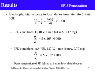
- 20. • Electrophoretic velocity to local deposition rate into 6 mm felt: – EPD conditions: E, 40 V, 1 min (41 mA, 1.17 mg) – EPD conditions: AA-PEI, 127 V, 4 min (6 mA, 0.79 mg) Results EPD Penetration 20Bakhoum, E.; Cheng, M. Journal of Applied Physics 2009, 105, 1–6. = 8 x 10⁴ >1000 Deep penetration of 3D felt up to 6 mm thick should occur = 5 x 10⁶ >1000 >1000
- 21. Blanks 3 mm carbon felt 6 mm graphite felt Results EPD Penetration 21
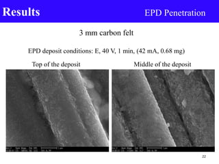
- 22. 3 mm carbon felt EPD deposit conditions: E, 40 V, 1 min, (42 mA, 0.68 mg) Top of the deposit Middle of the deposit Results EPD Penetration 22
- 23. 6 mm graphite felt EPD deposit conditions: E, 40 V, 1 min (41 mA, 1.17 mg) Top of the deposit Middle of the deposit Results EPD Penetration 23
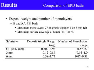
- 24. • Deposit weight and number of monolayers – E and AA-PEI bath • Maximum monolayers: 27 on graphite paper, 1 on 3 mm felt • Maximum surface coverage of 6 mm felt: ~31 % Results Comparison of EPD baths 24
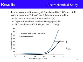
- 25. • Linear sweep voltammetry (LSV) from 0 to 1.0 V vs. SCE with scan rate of 50 mV/s in 2 M ammonium sulfite – As reaction increases, i proportional exp(V) – Deposit from ethanol bath into 6 mm graphite felt – EPD conditions: 40 V, 1 min, (41 mA, 1.17 mg) Results Electrochemical Study 25 i iblank
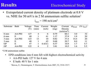
- 26. • Extrapolated current density of platinum electrode at 0.8 V vs. NHE for 50 mV/s in 2 M ammonium sulfite solution1 imax = 190 mA/cm2 Results Electrochemical Study 261Skavas, E.; Hemmingsen, T. Electrochimica Acta 2007, 52, 3510–3517. • EPD conditions into 6 mm felt with highest electrochemical activity • AA-PEI bath: 127 V for 4 min • E bath: 40 V for 1 min
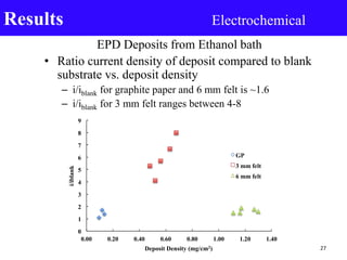
- 27. EPD Deposits from Ethanol bath • Ratio current density of deposit compared to blank substrate vs. deposit density – i/iblank for graphite paper and 6 mm felt is ~1.6 – i/iblank for 3 mm felt ranges between 4-8 Results Electrochemical 0 1 2 3 4 5 6 7 8 9 0.00 0.20 0.40 0.60 0.80 1.00 1.20 1.40 i/iblank Deposit Density (mg/cm2) GP 3 mm felt 6 mm felt 27
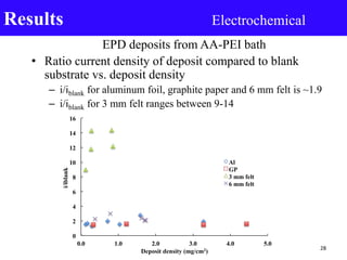
- 28. EPD deposits from AA-PEI bath • Ratio current density of deposit compared to blank substrate vs. deposit density – i/iblank for aluminum foil, graphite paper and 6 mm felt is ~1.9 – i/iblank for 3 mm felt ranges between 9-14 Results Electrochemical 28 0 2 4 6 8 10 12 14 16 0.0 1.0 2.0 3.0 4.0 5.0 i/iblank Deposit density (mg/cm2) Al GP 3 mm felt 6 mm felt
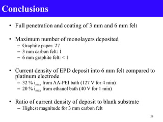
- 29. • Full penetration and coating of 3 mm and 6 mm felt • Maximum number of monolayers deposited – Graphite paper: 27 – 3 mm carbon felt: 1 – 6 mm graphite felt: < 1 • Current density of EPD deposit into 6 mm felt compared to platinum electrode – 32 % imax from AA-PEI bath (127 V for 4 min) – 20 % imax from ethanol bath (40 V for 1 min) • Ratio of current density of deposit to blank substrate – Highest magnitude for 3 mm carbon felt Conclusions 29
- 30. • Wet adhesion on graphite paper, 3 mm, and 6 mm felt • Determine EPD conditions for 1 monolayer of particles into 6 mm graphite felt • Determine how number of monolayers affect electrochemical activity of EPD deposits (Neil Verma M.S. thesis) Future work 30
- 31. • Professor Jan B. Talbot (UCSD) • Neil Verma for SEM image analysis (UCSD) • Dr. Richard Herz (UCSD) • Dr. Dave Genders and Dr. Peter Symons (Electrosynthesis Inc.) • Dr. Lloyd Brown (Thermochemical Solutions LLC.) • Roger Davenport and Robin Taylor (Leidos) This work was funded by the Department of Energy, Grant DE-FG36-07GO17002. Acknowledgements 31
- 32. Thank you! Committee Members: Professor Jan B. Talbot, Chair Professor Joanna M. McKittrick Professor Justin P. Opatkiewicz 32
Editor's Notes
- EPD is a method that deposits suspended particles in a liquid medium under an applied electric field into a substrate Zeta potential measures the potential difference of the diffusion layer, which is between the shear plane and the surrounding liquid Vacuum permittivity constant
- Peclet # study of transport through a medium expressed as the rate of advection by the rate of diffusion The Damköhler number is defined as the reaction rate by the diffusive mass transfer rate a is average pore radius, D is diffusion coefficient
- Slope ratio: rate of deposition
- Driving force (voltage), rate of reaction I proportional exp(V)