Multicast routing protocols in adhoc networks
•Download as PPTX, PDF•
4 likes•6,059 views

This document discusses routing and multicast protocols at the MAC, routing, and application layers. It describes key modules like transmission, receiving, and neighbor list handling at the MAC layer. At the routing layer, it discusses unicast and multicast routing tables, forwarding, tree construction, and session maintenance. The application layer handles data transmission, multicast session initiation and termination, and route repair. It also compares source tree and shared tree approaches, and soft state and hard state maintenance mechanisms.
Report
Share


Multicast routing protocols in adhoc networks
- 1. T S Pradeep Kumar VIT Chennai http://www.nsnam.com http://www.pradeepkumar.org
- 2. Medium Access Control (MAC Layer) ◦ Transmission and reception of packets is the main service ◦ Also arbitration to access the channel ◦ Three modules are handled Transmission Module Receiving Module Neighbor list handler
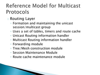
- 3. Routing Layer ◦ Formation and maintaining the unicast session/multicast group ◦ Uses a set of tables, timers and route cache ◦ Unicast Routing information handler ◦ Multicast Routing information handler ◦ Forwarding module ◦ Tree/Mesh construction module ◦ Session Maintenance Module ◦ Route cache maintenance module
- 4. Application Layer ◦ Data packet transmit/receive controller ◦ Multicast session initiator/terminator ◦ Joining a group ◦ Data packet propagation ◦ Route Repair
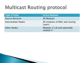
- 6. Type of Node Active Modules Source/Receiver All Modules Intermediate Nodes All modules of MAC and routing Layers Other Nodes Modules 2,3,8 and optionally module 4
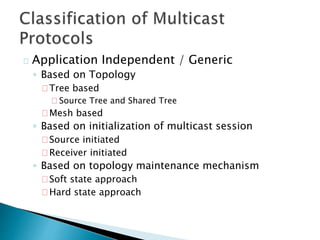
- 7. Application Independent / Generic ◦ Based on Topology Tree based Source Tree and Shared Tree Mesh based ◦ Based on initialization of multicast session Source initiated Receiver initiated ◦ Based on topology maintenance mechanism Soft state approach Hard state approach
- 8. Tree based ◦ Source Tree based The source is at the root ◦ Shared Tree based All the sources share the common tree with a core node at the root If there is a single point of failure (if core node failed), the route construction should happen again
- 10. Soft state approach ◦ Control packets are flooded periodically to refresh the route ◦ Packet delivery ratio is high Hard state approach ◦ Control packets are flooded only during a link break ◦ Packet delivery ratio is low because low control overhead
- 11. Source Tree based Shared Tree Based A single multicast tree maintained per source A single tree is shared by all sources in the tree Less scalable (increase in number of sources leads to increase in trees which affects the bandwidth) More scalable (performance will not be degraded when more multicast sessions or more souces are added) More memory is needed at the source nodes Less memory is needed as the tree is shared between the sources
- 12. Tries to find the nearest forwarding node rather than the shortest path between source and receiver Reduces number of data transmissions Uses hard state approach (to rejoin multicast group, the control packets are sent only during link breaks)
- 13. Tree initialisation Phase ◦ Join packets A receiver node floods the join control packets ◦ Reply Packets The existing members of the tree, on receiving join packets, respond with Reply control packets ◦ Reserve Packets When many such reply packets comes to the receiver nodes, then the receiver node select the minimum hop count route and send a Reserve Control packet to the member node.
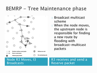
- 15. Node R3 Moves, I3 Broadcasts R3 receives and send a Reserve packet Broadcast multicast scheme When the node moves, the upstream node is responsible for finding a new route by flooding with broadcast-multicast packets
- 16. R3, I3 Links fails, R3 sends join and I3 reply R3 Send Reserve packets and rejoin the group Local Rejoin Scheme The corresponding sends the join packet if there is any break in the link. It is similar like tree initialization phase
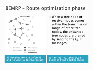
- 17. R3 Receives from I2 before I5 and R3 Sends a Reserve packet I5->I4->I3->I2, sends a Quit packet and thus a path is pruned When a tree node or receiver nodes comes within the transmission range of other tree nodes, the unwanted tree nodes are pruned by sending the Quit messages.