ntpc unchahar
•Download as DOC, PDF•
1 like•306 views
Khagesh Kumar Chandra completed a vocational training project at the NTPC Limited SIPAT Super Thermal Power Station from June 21, 2012 to June 18, 2012. The project covered an overview of power plants, supercritical technology, and the main equipment used in power generation including boilers, turbines, and their maintenance. Khagesh gained hands-on experience of the equipment and processes during guided tours of the plant.
Report
Share


ntpc unchahar
- 1. VOCATIONAL TRAINING PROJECT WORK PROJECT TITLE: SIPAT SUPER THERMAL POWER STATION DURATION: FROM 21/06/2012 TO18/06/2012 DETAILS OF STUDENT: NAME: KHAGESH KUMAR CHANDRA ROLL NO: 3353710033 COLLEGE: SSITM, BHILAI YEAR: 2012 PROJECT LOCATION: NTPC LIMITED, SIPAT DISTT: BILASPUR CHHATTISGARH - 495555
- 2. ACKNOWLEDGEMENT I am truly thankful to all the faculties/guides that imparted the lectures on various subjects/topics and took us to the plants in a guided study along with the detailed explaining about the plant and the machinery. I would also like to thank the Human resource department for permitting and organizing the training program for us. Signature Date- 18/06/2012 Name- KHAGESH KUMAR CHANDRA Roll no. - 3353710033 College- SSITM, BHILAI. Branch- MECHANICAL Year- 2012
- 3. CERTIFICATE THIS IS TO CERTIFY THAT MR. KHAGESH KUMAR CHANDRA HAS ATTENDED THE VOCATIONAL TRAINING PROGRAM FROM 18 may TO 21 June YEAR 2012 AND HAS PREPARED THE PROJECT REPORT. HIS/HER CONDUCT HAS BEEN “GOOD” DURING THE RAINING DURATION. PROJECT GUIDED: NAME DESIGNATION DEP/SECTION
- 4. DECLARATION THE PROJECT WORK TITLED: SIPAT THERMAL POWER PROJECT HAS BEEN CARRIED OUT AND THE REPORT PREPARED BY ME DURING 21 may TO 18 June UNDER THESUPERVISION OF GUIDES AT NTPC LTD/SIPAT SUPER THERMAL POWER PROJECT AND ORGANISED BY EMPLOYEE DEVELOPMENT CENTER, HUMAN RESOURCE DEPARTMENT. THIS IS THE ORIGINAL WORK CARRIED OUT BY ME AND HAS NEITHER BEEN TAKEN FROM ANY OTHER SOURCE NOR BEEN SUBMITTED TO ANY INSTITUTE OR ORGANISATION AS A FULFILMENT OF ANY OTHER CURRICULUM. SIGNATURE DATE: 18/06/2012 NAME: KHAGESH KUMAR CHANDRA ROLL NO. : 3353710033 COLLEGE: SSITM, BHILAI BRANCH: MECHANICAL YEAR/SEM: 2ND /4TH PROJECT WORK LOCATION: NTPC LTD, SIPAT DURATION: FROM 21/06/2012 TO 18/06/2012 DISCIPLINE: MECHANICAL ENGINEERING TOPICS COVERED: 1. Overview of power plant
- 5. 2. Super critical technology 3. Power plant equipments 4. Boiler 5. Turbine and its maintenance SIGNATURE DATE: 18/06/2012 NAME: KHAGESH KUMAR CHANDRA: ROLL NO. : 335371003 COLLEGE: SSITM, BHILAI BRANCH: MECHANICAL YEAR/SEM: 2ND /4TH INDEX S. No. TOPIC 1. NTPC and its joint ventures
- 6. 2. Super critical technology 3. Basic of power plant 4. Boiler 5. Turbine 6. Working of steam turbine 7. condenser 8. Turbine maintenance 9. 10. 11. oUR vISION: ”tO bE tHE wORLD’S lARGEST aND bEST pOWER pRODUCER, pOWERING iNDIA’S gROWTH.” NTPC limited A maharatan company.
- 7. Established in November 1975 for the nation’s sustainable power development. Core business is engineering, construction and operation of power generating plant and providing consultancy to power utilities. Listed on BSE and government of India holds a stake of 84.5%. Total installed capacity of 34194 MW (as on 31 march 2011) with 15 coal based & 7 gas based station and set to become 1, 28,000 MW company by 2032. Capacity under construction 14740 MW (approx) & PPA for more than 66000 MW. With a share of 17.75% of India’s installed capacity. Generates about 27.4% of India’s total generation.|~| Ranked 138th position in Fortune 500 in 2009. NTPC Limited and Its Joint Ventures NTPC hydro is formed to enter into hydel power sector. NTPC Electric Supply Company Ltd is formed to enter into power distribution & rural electrification. NTPC Vidyut Vyapar Nigam Limited formed for power trading. Bhartiya Rail Bijlee Company Ltd formed to construct & operate power plants for railways. Three joint Venture Company with SAIL to operate and maintain its captive power plants. To sustain the generation NTPC Ltd is also foraying in to coal mining. JV with ALsthom Power Generation AG to take up renovation and modernization of power plants.|~| Utility Power tech Ltd a JV with BSES to take up construction, erection and supervision works in power sector. NTPC Tamilnadu Energy Company Ltd (JV). Ratnagiri Gas & Power pvt ltd (JV). Meja Urja Nigam pvt ltd (JV). Aravali power company pvt ltd (JV). NTPC-BHEL Power projects pvt ltd (JV). SIPAT SUPER THERMAL POWER STATION
- 8. Sipat thermal power project is a cynosure of power generation of India. Situated in the vicinity of Bilaspur city. Pioneer of adopting super critical technology in India. India’s first 765 KV transmissions. Installed capacity 2890 MW Stage 1-3*660 MW Stage 2-2*500 MW Water source – Hasdeo right bank canal Coal linkage – Dipika mines, SECL. WHY SUPER-CRITICAL TECHNOLOGY? To reduce emission for each Kwh of electricity generated: Superior Environmental. 1% rise in efficiency reduces the CO2 emission by 2-3%. The most economical way to enhance efficiency. To achieve fuel cost saving: Economical Operating Flexibility. Reduces the boiler size/MW. To reduce start-up time.
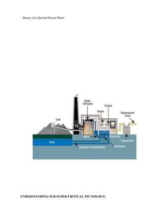
- 9. Basics of a thermal Power Plant: UNDERSTANDING SUB-SUPER CRITICAL TECNOLOGY:
- 10. Water when heated to sub critical temperature, pressure increases until it starts boiling. This temperature remains constant till all the water converted to steam. When all liquid converted to steam than again temperature starts rising. Sub critical boiler typically has a mean (boiler drum) to separate steam and water. The mass of this boiler drum, which limits the rate at which the sub critical boiler responds to the load changes. Too great a firing rate will result in high thermal stresses in the boiler drum. UNDERSTANDING SUPER CRITICAL TECHNOLOGY: When Water is heated at constant pressure above the critical pressure, its temperature will never be constant. No distinction between the liquid and gas, the mass density of the two phases remain same. No stage where the water exists as two phases and requires separation: No Drum. The actual location of the transition from liquid to steam in a once through super critical boiler is free to move with different condition: Sliding Pressure Operation.
- 11. BOILER DEFINITION: Steam Boiler are defined as ‘Any closed vessel exceeding 22.75 liters in capacity which is used expressively for generating steam under pressure and includes any mounting or other fitting attaches to such vessel, which is wholly, or partly under pressure when the steam is shut off. BOILER SPECIFICATIONS: Controlled Circulation with Rifle Tubing, Dry Bottom, Radiant Reheat, Single Drum, and Top Supported, Balanced Draft Furnace. (BHEL) Tilting, Tangential type firing. Steam Generating Cap. Of 1675 T/Hr at 172 ksc & 540o c. Furnace volume 16424 m3 . Depth = 15.8m Width = 19.2m Efficiency = 84.4% Sucks flue gas and Throws out via Chimney. Creates Negative Pr. in Ducts & Furnace. Maintain Furnace draft. Double Suction & Single Discharge Radial Fan. Arrangement of Main Boiler Economizer (3 stage) Boiler drum Down comers & BCW pumps Water wall & SCWs LTSH Divisional panel Final SH Reheater
- 12. Safety valves Burner and igniters BAHs Economizer Boiler economizers are feed-water heater in which the heat from waste gases is recovered to raise the temperature of feed-water supplied to the boiler. 6o c raise in feed water temperature, by economizers corresponds to 1% saving in fuel consumption. 220 C reduction in flue gas temperature increases boiler efficiency by 1%. Location and Arrangement: Ahead of air-heater in 2nd pass below LTSH Following the primary super-heater Counter-flow arrangement Horizontal placement (facilitate draining) Supported to prevent sagging, undue deflection and expansion. Stop valve and non-return valves incorporated to ensure recirculation in case of no feed-flow. Ash hopper below as flue gas takes a turn. Boiler Arrangement:
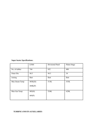
- 13. Super heater Specifications: LTSH Divisional Panel Platen Stage No. of rubber 744 432 400 Outer Dia 44.5 44.5 54 Joining Butt Butt Butt Max Steam Temp 405K(H) 444K(P) 513K 553K Max Gas Temp 405(H) 469(P) 524K 629K TURBINE AND ITS AUXILLARIES
- 14. Steam Turbines of following OEM’S are running in NTPC LMZ (Russia) KWU, Siemens (Germany) ABB-Alston (Germany) GEC-Alston (UK) SKODA, (chezkoslovakia) MHI (Japan) GE(USA) ANSALDO(Italy) TYPES OF TURBINE IMPULSE TURBINE- In a stage of Impulse turbine the pressure/enthalpy drop takes place only in fixed blades and not in the moving blades. REACTION TURBINE- In a stage of Reaction Turbine the Pressure/Enthalpy drop takes place in both the fixed and moving blades. WORKING OF STEAM TURBINE: A steam turbine works on the principle of conversion of high pressure & temperature steam into high kinetic energy, thereby giving torque to a moving rotor. For above energy conversion there is a requirement of converging/converging-diverging sections. Such above requirement is built up in the space between two consecutive blades of fixed of fixed and moving blades rows. THURST BALANCING Thurst bearing. IP/LP double flow(axial thurst-nullified) Balancing disc.
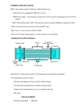
- 15. TURBINE LUBE OIL SYSTEM MOP: when turbine speed is>2840 rpm, MOP will take over Turbine lube oil is supplied by MOP pr. Is 2.6 ksc. MOPS also supply---1.governing oil 2.make up to seal oil system 3.barring gear oil 4.oil for LP bypass. AOP1: When turbine trips, AOP1 will come into service if speed<2840rpm or header pr<4.8ksc AOP2: will come into service if pr<4.5 ksc or AOP1 trips EOP: if pr< 1.1 ksc, in case of total AC failure JOP: cut in-510 rpm. Barring gear v/v-cut in 210 rpm, cut out 240 rpm. Condenser (it is a heat exchanger) Specification: 76mm of hg vacuum (-0.9 ksc gauge pr) is maintained in condenser. For maintaining vacuum we need: CW flow (provided by CW p/p, CW flow 3000 m3 /hour) Air evacuation system(ejectors & turbine sealing system) Reduce steam loading (load, any v/v to condenser passing). Dirty tube. STEAM TURBINE Generator rated speed 3000 rpm
- 16. Generator manufacturer Electrosila No. of bleedings 8 Length of the turbine 36.362m No. of stages HPT 17 IPT 11x2 LPT1 5x2 LPT2 5x2 Total 59 TURBINE MAINTAINNACE Steam Turbine Blading Steam turbines produce power by converting the energy in steam provided from a boiler or heat recovery steam generator (HRSG) into rotational energy as the steam passes through a turbine Stage. A turbine stage normally consists of a row of stationary blading and a row of rotating Blading. The purpose of the stationary blading is to direct the flow of the passing steam to the Rotating blading at the proper angle and velocity for the highest efficiency and extraction of Power. The purpose of the rotating blading is to convert the directed mass flow and steam Velocity into rotational speed and torque. Stationary blading may be referred to as nozzles, Vanes, stators, partitions, and stationary blading while rotating blades may be referred to as Buckets, blades, and rotating blading. A turbine may have a single row or stage of stationary and rotating blading or may have multiple rows or stages of blading.|~|
- 17. Why to go to location regularly? ALL PARAMETERS ARE NOT AVAILABLE IN UCB PERSONAL RELATIONSHIP WITH EQUIPMENTS PHYSICAL STATUS IS NOT KNOWN TO IDENTIFY ABNORMAL BEHAVIOR INSTRUMENTATION STATUS LEAKAGES Turbine Main Turbine HP IP LP Turbine driven BFP Points to check for Abnormal sound
- 18. Vibration Expansions Leakages (Oil, Steam, Water) Oil flows Pressures and Temperatures --------------|~|---------------