Open channel design
•
30 likes•24,895 views

This document discusses the design of open channels. It describes the process of designing channels to prevent silting and scouring. The key steps are determining the depth, bed width, side slopes, and longitudinal slope of the channel based on the discharge and sediment load. It also discusses different channel types and design methods for rigid and erodible channels. The main design methods covered are the permissible velocity method and tractive force method for erodible channels. Design procedures and examples are provided for rectangular and trapezoidal channel sections.
Report
Share


Open channel design
- 1. Open Channel Hydraulics Design of Channels 1 Hydraulics Dr. Mohsin Siddique Assistant Professor
- 2. Outcome of Today’s Lecture 2 After completing this lecture… The students should be able to: Understand the concepts of channel design Learn about various method applied in channel design Design channel section for both rigid boundary and erodible channels
- 3. Open Channel Design 3 It is the process to obtain a shape, slope and geometry of channel/canal which should not have objectionable silting and scouring. For example for a trapezoidal channel, it consists of determining; (1) depth, (2) bed width, (3) side slope and (4) longitudinal slope of the channel so as to produce a non-silting and non-scouring velocity for the given discharge and sediment load.
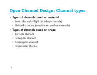
- 4. Open Channel Design: Channel types 4 Types of channels based on material Lined channels (Rigid boundary channels) Unlined channels (erodible or earthen channels) Types of channels based on shape Circular channel Triangular channel Rectangular channel Trapezoidal channel
- 5. Open Channel Design: Free Board 5 Free board is vertical distance between the design water surface and the top of the channel bank. It is provided to account for uncertainty in design, construction, and operation of the channel. The US Bureau of Reclamation recommends a minimum freeboard of 0.3m (1ft) for small channels and the following formula for estimating the freeboard (FB) for larger channels Where y is depth of channel in m (ft) and C is coefficient which varies from 0.7 (1.2) for small channels with capacity of 0.6 m3/s (20 ft3/s) to 0.9 (1.6) for larger channels with a capacity of 85m3/s (3000 ft3/s) or greater Sometime addition freeboard is required at out edge of curved section due to centrifugal force. yCFB =
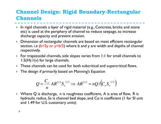
- 6. Channel Design: Rigid Boundary-Rectangular Channels 6 In rigid channels a layer of rigid material (e.g., Concrete, bricks and stone etc) is used at the periphery of channel to reduce seepage, to increase discharge capacity and prevent erosion. Dimension of rectangular channels are based on most efficient rectangular section. i.e (b=2y or y=b/2) where b and y are width and depths of channel respectively. For trapezoidal channels, side slopes varies from 1:1 for small channels to 1.5(H):1(v) for large channels. These channels can be used for both subcritical and supercritical flows. The design if primarily based on Manning’s Equation Where Q is discharge, n is roughness coefficient, A is area of flow, R is hydraulic radius, So is channel bed slope, and Co is coefficient (1 for SI unit and 1.49 for U.S. customary units) ( )2/13/22/13/2 / ooo o SCnQARSAR n C Q =⇒=
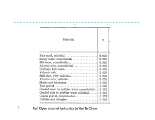
- 7. 7 Ref: Open channel hydraulics byVen Te Chow
- 8. Channel Design: Rigid Boundary Channels 8 Design Procedure: 1. Select a value of roughness coefficient ,n, and bottom slope, So, for the flow surface 2. Compute section factor from AR2/3 = nQ/(CoSo0.5), 3. Determine the channel dimensions and the flow depth for which AR2/3 is equal to the value determined in step 2. For example, for a trapezoidal section, select a value for the side slope, z, and compute several different ratios of bottom width Bo and flow depth y for which AR2/3 is equal to that determined in step 2. Select a ratio Bo/y that gives a cross section near to the best hydraulic section 4. Check that the minimum velocity is not less than that required to carry the sediment to prevent silting. 5.Add a suitable amount of freeboard. 6. Make a sketch providing all the dimensions.
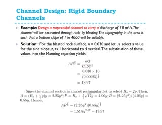
- 9. Channel Design: Rigid Boundary Channels 9 Example: Design a trapezoidal channel to carry a discharge of 10 m3/s.The channel will be excavated through rock by blasting.The topography in the area is such that a bottom slope of 1 in 4000 will be suitable. Solution: For the blasted rock surface, n = 0.030 and let us select a value for the side slope, z, as 1 horizontal to 4 vertical.The substitution of these values into the Manning equation yields
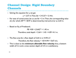
- 10. Channel Design: Rigid Boundary Channels 10 Solving this equation for y, we get y = 2.57 m.Then, Bo = 2×2.57 = 5.14m. For ease of construction, let us use Bo = 5 m.Then, the corresponding value of y for which AR2/3= 18.97 is determined by trial and error as 2.64 m. Based on Eq. of Freeboard, FB =0.8 × (2.64)0.5 = 1.45 m. Therefore, total depth = 2.64 + 1.45 = 4.09 =4.1 m. The flow area for a flow depth of 2.64 m is 14.94 m2. Therefore, the flow velocity = 10/14.94 = 0.67 m/s. This is close to the minimum allowable flow velocity; thus, a bottom width of 5 m and a cross section depth of 3.4 m is satisfactory.
- 11. Channel Design: Rigid Boundary Channels 11 Make a clear sketch of channel showing all dimensions
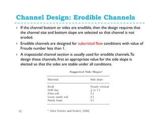
- 12. Channel Design: Erodible Channels 12 If the channel bottom or sides are erodible, then the design requires that the channel size and bottom slope are selected so that channel is not eroded. Erodible channels are designed for subcritical flow conditions with value of Froude number less than 1. A trapezoidal channel section is usually used for erodible channels.To design these channels, first an appropriate value for the side slope is elected so that the sides are stable under all conditions.
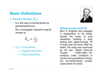
- 13. Basic Definitions Froude’s Number (FN) It is the ratio of inertial forces to gravitational forces. For a rectangular channel it may be written as FN= 1 Critical Flow > 1 Super-Critical Flow < 1 Sub-Critical Flow gy V NF = William Froude (1810-79) Born in England and engaged in shipbuilding. In his sixties started the study of ship resistance, building a boat testing pool (approximately 75 m long) near his home. After his death, this study was continued by his son, Robert Edmund Froude (1846-1924). For similarity under conditions of inertial and gravitational forces, the non-dimensional number used carries his name. 13
- 14. Channel Design: Erodible Channels 14 There are many method available but the following two methods are discussed here. Permissible velocity method and Tractive force method.
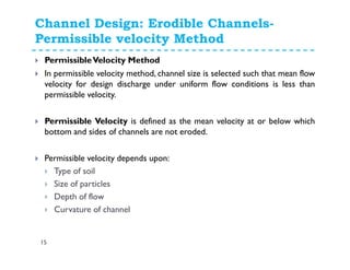
- 15. Channel Design: Erodible Channels- Permissible velocity Method 15 PermissibleVelocity Method In permissible velocity method, channel size is selected such that mean flow velocity for design discharge under uniform flow conditions is less than permissible velocity. Permissible Velocity is defined as the mean velocity at or below which bottom and sides of channels are not eroded. Permissible velocity depends upon: Type of soil Size of particles Depth of flow Curvature of channel
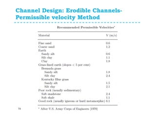
- 16. Channel Design: Erodible Channels- Permissible velocity Method 16
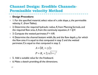
- 17. Channel Design: Erodible Channels- Permissible velocity Method 17 Design Procedure: 1. For the specified material, select value of n, side slope, z, the permissible velocity, V, (fromTables). 2. Determine the required hydraulic radius, R, from Manning formula, and the required flow area, A, from the continuity equation, A = Q/V. 3. Compute the wetted perimeter, P = A/R. 4. Determine the channel bottom width, Bo, and the flow depth, y, for which the flow area A is equal to that computed in step 2 and the wetted perimeter, P, is equal to that computed in step 3. 5. Add a suitable value for the freeboard. 6. Make a sketch providing all the dimensions. ( ) 2 12 zyBP yzyBA o o ++= +=
- 18. Channel Design: Erodible Channels- Permissible velocity Method 18 Design a channel to carry a flow of 6.91 m3/s.The channel will be excavated through stiff clay at a channel bottom slope of 0.00318. Solution: For stiff clay, n = 0.025, suggested side slope, z = 1 : 1 (fromTable ), and the permissible flow velocity (fromTable ) is 1.8 m/s. Hence, A = 6.91/1.8 = 3.83 m2 Substituting values for V, n, and So into Manning equation, and solving for R, we get R = 0.713 m. Hence, P = A/R=3.83/0.713= 5.37m 2/13/2 o o SAR n C Q =
- 19. Channel Design: Erodible Channels- Permissible velocity Method 19 Substitution into expressions for P and A and equating them to the values computed above, we obtain Eliminating Bo from these equations yields Solution of above quadratic equation yields y=1.22m and hence Bo=1.9m Freeboard (FB)=0.8x(1.22)0.5=0.99 Total depth of channel section=1.22+0.99=2.21m ( ) ( ) yByB yyByyB oo oo 83.211237.5 .183.3 2 +=++= +=+= 083.337.583.1 2 =+− yy
- 20. Channel Design: Erodible Channels- Permissible velocity Method 20 Make a clear sketch of channel showing all dimensions
- 21. Channel Design: Erodible Channels- Permissible velocity Method 21 Problem: A grass-lined drainage channel is to carry a discharge of 2000 cfs at a maximum velocity of 4.0 fps.The side slopes of the channel will be 4:1 and the longitudinal slope of the channel will be 0.001. Design the channel for Manning’s n values of 0.03 and 0.035. Answer: for n=0.03, y=4.9ft, Bo=83ft and FB=3.1ft for n=0.035, y=7.7ft, Bo=34.2ft and FB=3.9ft
- 22. Channel Design: Erodible Channels- Tractive Force Method 22 Tractive Force Method Scour and erosion process can be viewed in rational way by considering forces acting on particles lying on channel bottom or sides. The channel is eroded if resultant of forces tending to move particles is greater than resultant of forces resisting motion. This concept is referred as tractive force approach. Tractive Force The force exerted by flowing water on bottom and sides of channel is called tractive force. In uniform flow, this force is equal to component of weight acting in direction of flow and is given by Where, ooo ySRS γγτ ==
- 23. Channel Design: Erodible Channels- Tractive Force Method 23 CriticalTractive Force The force at which channel material begins to move from stationery condition is called critical tractive force. Distribution ofTractive Force Distribution of tractive force or shear stress over channel perimeter is not uniform. For trapezoidal channels, unit tractive force at channel bottom may be assumed equal to (γ y So) and at channel sides equal to 0.75 γ y So Reduction Factor for Channel Sides Reduction factor (tractive force ratio) for critical tractive force on channel sides is: i.e K=Permissible Tractive force on side slope/Critical Tractive force
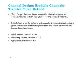
- 24. Channel Design: Erodible Channels- Tractive Force Method 24 Effect of angle of repose should be considered only for coarse non cohesive materials and can be neglected for fine cohesive materials. Critical shear stress for cohesive and non cohesive materials is given in the figures.These values are for straight channels and should be reduced for sinuous channels as below: Slightly sinuous channels = 10% Moderately sinuous channels = 25% Highly sinuous channels = 40%
- 25. Basic Definitions Channel classification 25 Straight Channel Braided Channel Meandering Channel Sinuosity is ratio of actual path length to shortest path length
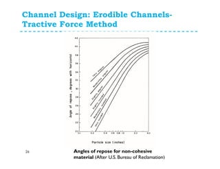
- 26. Channel Design: Erodible Channels- Tractive Force Method 26 Angles of repose for non-cohesive material (After U.S. Bureau of Reclamation)
- 27. Channel Design: Erodible Channels- Tractive Force Method 27 Permissible shear stress for noncohesive materials (After U.S. Bureau of Reclamation)
- 28. Channel Design: Erodible Channels- Tractive Force Method 28 Permissible shear stress for cohesive materials (After U.S. Bureau of Reclamation)
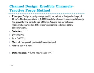
- 29. Channel Design: Erodible Channels- Tractive Force Method 29 Example: Design a straight trapezoidal channel for a design discharge of 10 m3/s.The bottom slope is 0.00025 and the channel is excavated through fine gravel having particle size of 8 mm.Assume the particles are moderately rounded and the water carries fine sediment at low concentrations. Solution: Q = 10 m3/s; So = 0.00025; Material: Fine gravel, moderately rounded; and Particle size = 8 mm. Determine: Bo = ? And Flow depth, y = ?
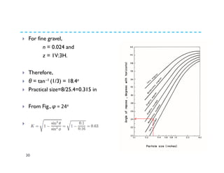
- 30. 30 For fine gravel, n = 0.024 and z = 1V:3H. Therefore, θ = tan−1 (1/3) = 18.4o Practical size=8/25.4=0.315 in From Fig., φ = 24o Hence,
- 31. 31 Critical shear stress from Fig = 0.15 lbs/ft2 = 7.18 N/m2. Since the channel is straight, we do not have to make a correction for the alignment. The permissible shear stress for the channel side is =7.18× 0.63 = 4.52 N/m2.
- 32. 32 Now, the unit tractive force on the side = 0.76γySo = 0.76×999×9.81y×0.00025 = 1.862y By equating the unit tractive force to the permissible stress, we obtain 1.862y = 4.52 Or y = 2.43m The channel bottom width, Bo, needed to carry 10 m3/s may be determined from the Mannings’ equation ( ) ( ) QS yzB yzyB yzyB n QSAR n o o o = ++ + + = 0 3/2 2 0 3/2 12 1 1
- 33. 33 By substituting n = 0.024, z = 3, y = 2.43, So = 0.00025, and Q = 10 m3/s, and solving for Bo, we obtain Bo = 8.24m Free Board, FB, = 0.8 × (2.43)0.5 = 1.40 m. For a selected freeboard of 1.4 m, the depth of section = 2.43 + 1.4 = 3.82 m. For ease of construction, select a bottom width, Bo = 8.25 m.
- 34. 34 Make a clear sketch of channel showing all dimensions
- 35. Thank you Questions…. Feel free to contact: 35