


Process model rup
- 2. Objectives To introduce software process models To describe three generic process models and when they may be used To describe outline process models for requirements engineering, software development, testing and evolution To explain the Rational Unified Process model To introduce CASE technology to support software process activities
- 3. Topics covered Software process models Process iteration Process activities The Rational Unified Process Computer-aided software engineering
- 4. The software process A structured set of activities required to develop a software system • • • • Specification; Design; Validation; Evolution. A software process model is an abstract representation of a process. It presents a description of a process from some particular perspective.
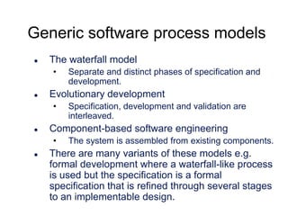
- 5. Generic software process models The waterfall model • Evolutionary development • Specification, development and validation are interleaved. Component-based software engineering • Separate and distinct phases of specification and development. The system is assembled from existing components. There are many variants of these models e.g. formal development where a waterfall-like process is used but the specification is a formal specification that is refined through several stages to an implementable design.
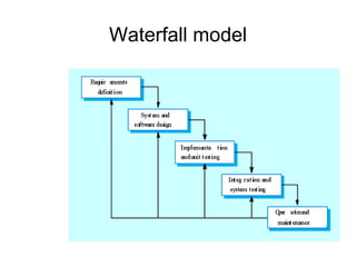
- 7. Waterfall model phases Requirements analysis and definition System and software design Implementation and unit testing Integration and system testing Operation and maintenance The main drawback of the waterfall model is the difficulty of accommodating change after the process is underway. One phase has to be complete before moving onto the next phase.
- 8. Waterfall model problems Inflexible partitioning of the project into distinct stages makes it difficult to respond to changing customer requirements. Therefore, this model is only appropriate when the requirements are well-understood and changes will be fairly limited during the design process. Few business systems have stable requirements. The waterfall model is mostly used for large systems engineering projects where a system is developed at several sites.
- 9. Evolutionary development Exploratory development • Objective is to work with customers and to evolve a final system from an initial outline specification. Should start with well-understood requirements and add new features as proposed by the customer. Throw-away prototyping • Objective is to understand the system requirements. Should start with poorly understood requirements to clarify what is really needed.
- 11. Evolutionary development Problems • • • Lack of process visibility; Systems are often poorly structured; Special skills (e.g. in languages for rapid prototyping) may be required. Applicability • • • For small or medium-size interactive systems; For parts of large systems (e.g. the user interface); For short-lifetime systems.
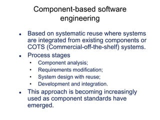
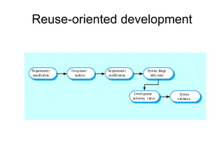
- 12. Component-based software engineering Based on systematic reuse where systems are integrated from existing components or COTS (Commercial-off-the-shelf) systems. Process stages • • • • Component analysis; Requirements modification; System design with reuse; Development and integration. This approach is becoming increasingly used as component standards have emerged.
- 14. Process iteration System requirements ALWAYS evolve in the course of a project so process iteration where earlier stages are reworked is always part of the process for large systems. Iteration can be applied to any of the generic process models. Two (related) approaches • • Incremental delivery; Spiral development.
- 15. Incremental delivery Rather than deliver the system as a single delivery, the development and delivery is broken down into increments with each increment delivering part of the required functionality. User requirements are prioritised and the highest priority requirements are included in early increments. Once the development of an increment is started, the requirements are frozen though requirements for later increments can continue to evolve.
- 17. Incremental development advantages Customer value can be delivered with each increment so system functionality is available earlier. Early increments act as a prototype to help elicit requirements for later increments. Lower risk of overall project failure. The highest priority system services tend to receive the most testing.
- 18. Extreme programming An approach to development based on the development and delivery of very small increments of functionality. Relies on constant code improvement, user involvement in the development team and pairwise programming. Covered in Chapter 17
- 19. Spiral development Process is represented as a spiral rather than as a sequence of activities with backtracking. Each loop in the spiral represents a phase in the process. No fixed phases such as specification or design - loops in the spiral are chosen depending on what is required. Risks are explicitly assessed and resolved throughout the process.
- 20. Spiral model of the software process
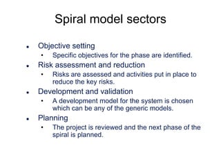
- 21. Spiral model sectors Objective setting • Risk assessment and reduction • Risks are assessed and activities put in place to reduce the key risks. Development and validation • Specific objectives for the phase are identified. A development model for the system is chosen which can be any of the generic models. Planning • The project is reviewed and the next phase of the spiral is planned.
- 22. Process activities Software specification Software design and implementation Software validation Software evolution
- 23. Software specification The process of establishing what services are required and the constraints on the system’s operation and development. Requirements engineering process • • • • Feasibility study; Requirements elicitation and analysis; Requirements specification; Requirements validation.
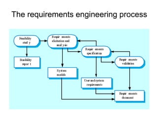
- 24. The requirements engineering process
- 25. Software design and implementation The process of converting the system specification into an executable system. Software design • Implementation • Design a software structure that realises the specification; Translate this structure into an executable program; The activities of design and implementation are closely related and may be inter-leaved.
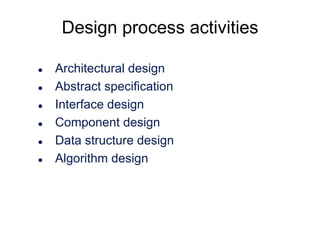
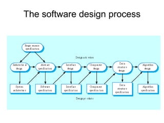
- 26. Design process activities Architectural design Abstract specification Interface design Component design Data structure design Algorithm design
- 27. The software design process
- 28. Structured methods Systematic approaches to developing a software design. The design is usually documented as a set of graphical models. Possible models • • • • • Object model; Sequence model; State transition model; Structural model; Data-flow model.
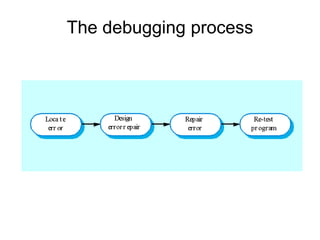
- 29. Programming and debugging Translating a design into a program and removing errors from that program. Programming is a personal activity - there is no generic programming process. Programmers carry out some program testing to discover faults in the program and remove these faults in the debugging process.
- 31. Software validation Verification and validation (V & V) is intended to show that a system conforms to its specification and meets the requirements of the system customer. Involves checking and review processes and system testing. System testing involves executing the system with test cases that are derived from the specification of the real data to be processed by the system.
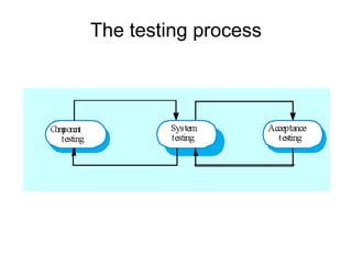
- 33. Testing stages Component or unit testing • • System testing • Individual components are tested independently; Components may be functions or objects or coherent groupings of these entities. Testing of the system as a whole. Testing of emergent properties is particularly important. Acceptance testing • Testing with customer data to check that the system meets the customer’s needs.
- 34. Testing phases
- 35. Software evolution Software is inherently flexible and can change. As requirements change through changing business circumstances, the software that supports the business must also evolve and change. Although there has been a demarcation between development and evolution (maintenance) this is increasingly irrelevant as fewer and fewer systems are completely new.
- 36. System evolution
- 37. The Rational Unified Process A modern process model derived from the work on the UML and associated process. Normally described from 3 perspectives • • • A dynamic perspective that shows phases over time; A static perspective that shows process activities; A practive perspective that suggests good practice.
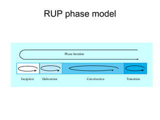
- 38. RUP phase model Phase iteration Inception Elaboration Construction Transition
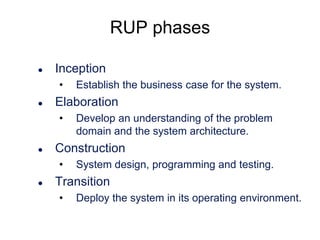
- 39. RUP phases Inception • Elaboration • Develop an understanding of the problem domain and the system architecture. Construction • Establish the business case for the system. System design, programming and testing. Transition • Deploy the system in its operating environment.
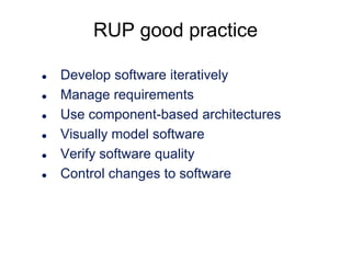
- 40. RUP good practice Develop software iteratively Manage requirements Use component-based architectures Visually model software Verify software quality Control changes to software
- 41. Static workflows Wor kfl ow De scr ip tio n Bu si nes s m ode lli ng T he bu si nes s p roce sse s a re m ode ll ed u si ng bu si nes s u se c ase s. R e qui rem en ts Ac to rs who interac t w it h the sy st em a re i den ti fied and use ca ses ar e deve loped t o m ode l t he sys tem re qu ire m en ts . Ana lysi s and de si gn A des ign m ode l is crea ted and do c u m en ted u si ng a rch it ec tu ral m ode ls, c om ponen t m ode ls , obj e ct m ode ls and sequ e nce mod el s. Im pl em en tati on T he co m pon e nt s in t he sys tem are im p lem en ted and st ru ct ured i n to im plem en tati on sub- sys tems . Au to m ati c c ode gen e ra ti on fro m d e sign m ode ls he lps ac c eler at e this p roces s. T es t T es ti ng is a n it erati ve p roce ss tha t is ca rri ed ou t i n con junc ti on w it h im plem en tati on. S ys tem te sti ng foll ows t he c o m pl et ion of the im plem en tati on. Dep loy m en t A produc t rel eas e is crea ted , d ist ribu ted t o us e rs and i ns tall ed i n the ir wo rkp lace . Con fi gu rati on and chang e m anag e m e n t T hi s suppo rting wo rkf low m anaged Ch a pt e r 29) . P ro je ct m anag e m e n t T hi s suppo rting wo rkf low m anage s the sy st em deve lop m en t (see Ch a pt e r 5) . E nvi ron m en t T hi s w ork fl ow is con c ern e d w it h ma king app ropr ia te s of twa re t oo ls ava il ab le t o the so ft wa re deve lop m en t tea m . change s to th e sys tem (see
- 42. Computer-aided software engineering Computer-aided software engineering (CASE) is software to support software development and evolution processes. Activity automation • • • • • Graphical editors for system model development; Data dictionary to manage design entities; Graphical UI builder for user interface construction; Debuggers to support program fault finding; Automated translators to generate new versions of a program.
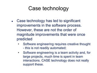
- 43. Case technology Case technology has led to significant improvements in the software process. However, these are not the order of magnitude improvements that were once predicted • • Software engineering requires creative thought - this is not readily automated; Software engineering is a team activity and, for large projects, much time is spent in team interactions. CASE technology does not really support these.
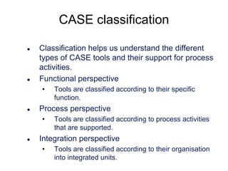
- 44. CASE classification Classification helps us understand the different types of CASE tools and their support for process activities. Functional perspective • Process perspective • Tools are classified according to their specific function. Tools are classified according to process activities that are supported. Integration perspective • Tools are classified according to their organisation into integrated units.
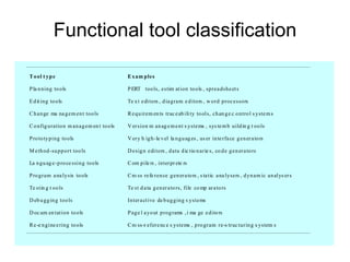
- 45. Functional tool classification T o ol t yp e E x am ples P la n ning to ols P ERT too ls, estim at ion to ols , sprea dshe et s E d it ing to ols Te x t e di tors , d ia gram e d itors , w ord proc essors C h an ge ma na g em en t too ls R e qu irem en ts trac e ab ili ty to ol s, ch an g e c o ntro l s yste m s C o nfig uratio n m an ag em en t to ols V er sion m an ag e m e nt s ystems , sys te m b uild in g t oo ls P ro to ty ping to ols V er y h ig h-le v el la n gu ag es , us er in te rfa ce g en er a to rs M e th od -su pp ort too ls D esig n e di tors , d ata d ic tio n arie s, co d e g en er a to rs La n gu ag e -p ro ce ssi ng to ols C om pile rs , inter pr ete rs P ro gram a na lysis to ols C ro ss re fe ren ce g en er a to rs , s ta tic a na lysers , d yn am ic an al ys er s Te stin g t oo ls Te st d a ta g en er a to rs, file co mp ar a to rs D eb u gg in g too ls Inter a ct ive de b ug ging s ystems D oc um en tat ion to ols P ag e l a yo ut prog rams , i ma ge e dito rs R e -e n gine e ring to ols C ro ss-r efer e nc e s ystems , p ro gram re-s truc turin g s ystem s
- 46. Activity-based tool classification Re -eng ineering t ools Testing tools Debugg ing tools Pr og r am analysis tools La nguage- pr ocessing t ools Met hod suppor t t ools Pr otot yping tools Configurat ion m anagem ent t ools Change m anagem ent t ools Docum entat ion t ools Edit ing tools Planning tools Specif ication Design I mplem entat ion V ificat ion er and Validat ion
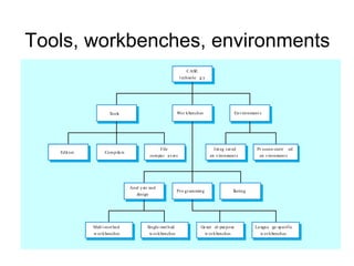
- 47. CASE integration Tools • Workbenches • Support individual process tasks such as design consistency checking, text editing, etc. Support a process phase such as specification or design, Normally include a number of integrated tools. Environments • Support all or a substantial part of an entire software process. Normally include several integrated workbenches.
- 48. Tools, workbenches, environments CASE t echnolo g y Wor kbenches Tools Edit ors Com pile rs File com pa r a t or s Anal ysis and design Mult i-m et hod w or kbenches Single- met hod w or kbenches Environment s I nt eg r at ed en vironment s Pr o gr am ming Pr ocess- centr ed en vironment s T esting Ge ner al- pur pose w or kbenches La ngua ge- specif ic w or kbenches