


Retrofitting
- 1. RETROFITTING OF BUILDINGS Submitted by: Mr. Yash Kumar Submitted to: Department Of Civil Engineering
- 2. CONTENTS Introduction Need of retrofitting Goals of retrofitting To retrofit or not ? Steps of retrofit Condition assessments of buildings Materials used for retrofitting Classification of retrofitting techniques Retrofitting of RCC buildings Conclusion Appendix
- 3. INTRODUCTION TO RETROFITTING Actions that improve the strength and other attributes of the integrity of a structure or a member with respect to seismic forces. Sometimes, the terms ‘seismic rehabilitation’, ‘seismic upgradation’ and ‘seismic strengthening’ are used in lieu of ‘seismic retrofit’. It is intended to mitigate the effect of future earthquakes. Retrofit is done before the occurrence of the earthquake (as a preventive measure) in an undamaged building, while rehabilitation is done in a building that is already damaged.
- 4. NEED OF RETROFITTING The need for seismic retrofitting can arise due to any of the following reasons: Building not designed to code. subsequent updating of code and design practice Subsequent upgrading of seismic zone deterioration of strength and aging modification of existing structure In India, almost 85% of total buildings are non-engineered buildings made up of earthen walls, stone walls, brick masonry walls, etc. These buildings are more vulnerable.
- 5. GOALS OF RETROFITTING To increase the lateral strength and stiffness of the building. To increase the ductility and aims to avoid the brittle modes of failure. To increase the integral action and continuity of the members in a building. To eliminate or reduce the effects of irregularities. To enhance redundancy in the lateral load resisting system. This aims to eliminate the possibility of progressive collapse. To ensure adequate stability against overturning and sliding.
- 6. TO RETROFIT OR NOT ? A decision depends on many factors. Lifeline buildings, such as hospitals must necessarily be retrofitted, in view of their extreme importance. But should the aim of retrofit be to raise this capacity to 100 percent • For lifeline buildings such as fire stations, hospitals, power stations, telephone exchanges, television stations, radio stations, railway stations, air ports; • Important service and community buildings such as schools, cinema halls, multiplexes, marriage and other assembly halls, the capacity should be raised to 100 percent
- 7. STAGES OF RETROFITTING Selection of the objective of retrofit Reviewing initial considerations Obtaining information of the building Seismic evaluation Decision to retrofit or demolish Selection and design of retrofit strategies Verification of the retrofit scheme Construction Maintenance and monitoring
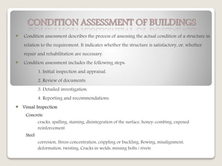
- 8. CONDITION ASSESSMENT OF BUILDINGS Condition assessment describes the process of assessing the actual condition of a structure in relation to the requirement. It indicates whether the structure is satisfactory, or, whether repair and rehabilitation are necessary. Condition assessment includes the following steps: 1. Initial inspection and appraisal. 2. Review of documents. 3. Detailed investigation. 4. Reporting and recommendations. Visual Inspection Concrete cracks, spalling, staining, disintegration of the surface, honey-combing, exposed reinforcement Steel corrosion, Stress concentration, crippling or buckling, Bowing, misalignment, deformation, twisting, Cracks in welds, missing bolts / rivets
- 9. Detailed Investigation 1. Obtaining the properties of the structural materials used in the building. 2. Determining the type and disposition of reinforcement in building. 3. Locating deteriorated material and other defects. A number of tests are available to study the condition of the material in a structure: Non- Destructive Tests • Rebound Hammer test • Thermal methods • Radiography • Electromagnetic techniques • Stress wave propagation method Intrusive Tests • Core test • In-Situ Shear test • Flat-Jack test • In-Situ Permeability
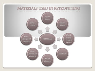
- 10. MATERIALS USED IN RETROFITTING MATERIALS Epoxy Resins Epoxy Mortar Quick Setting Cement Mortar Shortcrete Micro- Concrete Fibre- Reinforced Concrete Fibre- Reinforced Polymer Ferro- cement
- 11. CLASSIFICATION OF RETROFIT TECHNIQUES Local Retrofit Strategies Global Retrofit Strategies • Global Retrofit Strategies: To provide increased lateral stiffness and strength to the building as a whole. And, to ensure that a total collapse of the building does not occur. • Local Retrofit Strategies: To avoid failure of the components, and also thereby enhance the overall performance of the structure • More than one combination of local and global retrofit strategies is possible. • The structural engineer must work out an appropriate, practically and economical solution.
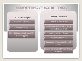
- 12. RETROFITTING OF RCC BUILDINGS LOCAL Techniques Concrete Jacketing, Steel Jacketing Fibre-Reinforced polymer (FRP) sheet wrapping. GLOBAL Techniques Addition of Infill Walls Addition of Shear walls or wing walls or Buttress Walls Addition of Steel Braces Addition of Frames Reduction of Irregularities and Mass Energy Dissipation Devices & Base Isolation
- 13. • To increase the lateral stiffness of a storey. • Addition of infill walls in the ground storey is a viable option to retrofit buildings. • Due to the ‘strut action’ of the infilled walls, the flexural and shear forces and the ductility demand on the ground storey columns are reduced. ADDITION OF INFILL WALLS
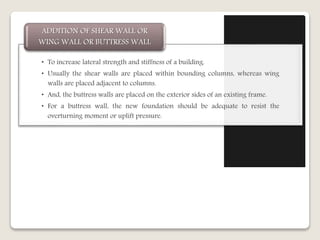
- 14. • To increase lateral strength and stiffness of a building. • Usually the shear walls are placed within bounding columns, whereas wing walls are placed adjacent to columns. • And, the buttress walls are placed on the exterior sides of an existing frame. • For a buttress wall, the new foundation should be adequate to resist the overturning moment or uplift pressure. ADDITION OF SHEAR WALL OR WING WALL OR BUTTRESS WALL
- 15. Addition of shear wall Addition of Buttress wall Addition of wing wall
- 16. • It can be inserted in a frame to provide lateral stiffness, strength & ductility. • The braces can be added at the exterior frames and for an open ground storey, the braces can be placed in appropriate bays with least disruption of the building use. • Since, the braces are connected to the frames at the beam-column joints, the forces resisted by the braces are transferred to the joints in the form of axial forces ADDITION OF STEEL BRACES
- 17. Addition of steel braces
- 18. • Addition of infill walls, shear walls or braces can alleviate the deficiency of soft or weak storeys. • Discontinuous components such as floating columns can be extended up to the foundation. • Although partial demolition can have impact on the appearance of the building, it can be an effective measure to reduce irregularity. • The mass can be reduced through demolition of unaccounted additional storeys, replacement of heavy cladding or removal of heavy storage. REDUCTION OF IRREGULARITIES AND MASS
- 19. • Base Isolation • A base isolation system decouples the superstructure from the seismic ground motions. The objective is to prevent the superstructure of the building from absorbing the earthquake energy. • The principle is to introduce flexibility at the base of a structure in the horizontal plane, while at the same time introducing damping elements to restrict the amplitude of the motion caused by the earthquake. • The role of a energy dissipation device is to increase the absorption of seismic energy in the structure. • Friction dampers • Metallic dampers • Viscoelastic Dampers • Viscous Dampers BASE ISOLATION AND ENERGY DISSIPATION DEVICES
- 20. ADDITION OF INFILL WALLS • Merits • Increases lateral stiffness of a storey • Can support vertical load if adjacent column fails • Demerits • May have premature • Does not increase ductility • Increases weight ADDITION OF SHEAR, WING WALLS OR BUTTRESS WALL • Merits • Increases lateral strength and stiffness • May increase ductility • Demerits • May increase design base shear • Stresses concentrated near the walls • Need adequate foundation ADDITION OF BRACES • Merits • Increases lateral strength and stiffness • May increase ductility • Demerits • Connection of braces to an existing frame can be difficult ADDITION OF FRAMES • Merits • Increases lateral strength and stiffness • May increase ductility • Demerits • Needs adequate foundations Comparison Of Global Strategies
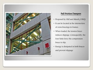
- 21. Pall Friction Dampers • Proposed by Pall and Marsh (1982). • It can be located at the intersection of cross bracings in frames. • When loaded, the tension brace induces slippage. Consequently, the four links force the compression brace to slip. • Energy is dissipated in both braces and prevent slippage
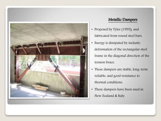
- 22. Metallic Dampers • Proposed by Tyler (1995), and fabricated from round steel bars. • Energy is dissipated by inelastic deformation of the rectangular steel frame in the diagonal direction of the tension brace. • These dampers are stable, long-term reliable, and good resistance to thermal conditions. • These dampers have been used in New Zealand & Italy.
- 23. Visco-elastic Dampers (VED) • Proposed by Aiken and Kelly (1990). • It has been used in structures where the damper undergoes shear deformations. • A typical VED consists of viscoelastic layers bonded to steel plates. • When mounted to a structure, shear deformations and consequently energy dissipations take place when relative motions occurs.
- 24. Fluid Viscous Dampers • Proposed by Constantinou and Symons (1992). • These dampers possess linear viscous behavior and are relatively insensitive to temperature changes. • It is filled with silicone oil, consists of a steel piston and an accumulator. • The force in the damper is generated by a pressure difference across the piston head. The reduction in volume causes a restoring force, which is prevented by the accumulator.
- 25. Tuned Mass Dampers (TMD) • It consists of a mass, which moves relative to the structures and is attached to it by a spring. • It reduces the vibration of a system with a comparatively lightweight component so that the worst-case vibrations are less intense. • When the structure vibrates, it excites the TMD and the kinetic energy is transferred from the structures to the TMD and is absorbed by its damping component.
- 26. ATC Tower Delhi Airport (New Delhi) — a 50-ton tuned mass damper installed just beneath the ATC floor at 90m. Statue of Unity (Gujarat) - a 400-ton tuned mass damper located at the chest level of Sardar Patel statue. Taipei 101 skyscraper — Contains the world's largest and heaviest tuned mass dampers, at 660 metric tons
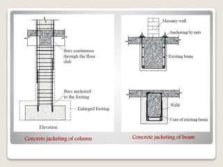
- 27. • It involves addition of a layer of concrete, longitudinal bars and closely spaced ties. The jacket increases both the flexural strength and shear strength of the column. • To increase the flexural strength, the additional longitudinal bars need to be anchored to the foundation. • If the jacket is only partially around the existing column, the new bars can be welded to the existing bars. • It involves drilling holes in the existing beam. But drilling holes for the stirrups at closing spacing damages the beam. CONCRETE JACKETING
- 28. Concrete jacketing of column Concrete jacketing of beam
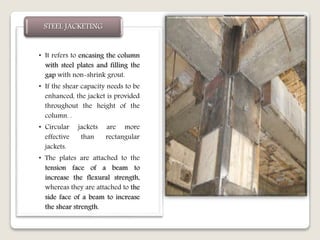
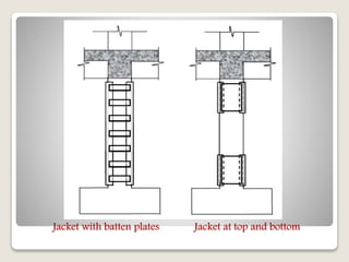
- 29. • It refers to encasing the column with steel plates and filling the gap with non-shrink grout. • If the shear capacity needs to be enhanced, the jacket is provided throughout the height of the column. . • Circular jackets are more effective than rectangular jackets. • The plates are attached to the tension face of a beam to increase the flexural strength, whereas they are attached to the side face of a beam to increase the shear strength. STEEL JACKETING
- 30. Jacket with batten plates Jacket at top and bottom
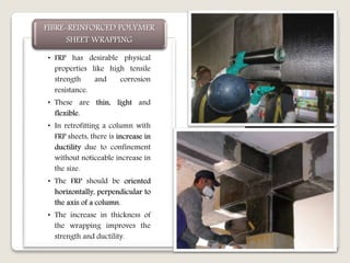
- 31. • FRP has desirable physical properties like high tensile strength and corrosion resistance. • These are thin, light and flexible. • In retrofitting a column with FRP sheets, there is increase in ductility due to confinement without noticeable increase in the size. • The FRP should be oriented horizontally, perpendicular to the axis of a column. • The increase in thickness of the wrapping improves the strength and ductility. FIBRE-REINFORCED POLYMER SHEET WRAPPING
- 32. CONCRETE JACKETING • Merits • Increases flexural & shear strengths and ductility • Easy to analyse • Good compatibility • Demerits • Size of member increases • Anchoring of bars involves drilling of holes in the existing concrete STEEL JACKETING • Merits • Increases shear strength and ductility • Minimal increase in size • Demerits • Needs protection against corrosion and fire • Use of bolts involves drilling in the existing concrete FRP SHEETS WRAPPING • Merits • Increases shear strength and ductility • Minimal increase in size • Rapid installation • Demerits • Needs protection against fire Comparison Of Local Strategies
- 33. CONCLUSION • To determine the actual condition of the building. • To identify the deficiencies of the building • The compatibility of deformation should be ensured by proper detailing of the connections. Importance of condition assessment • When a building is severely deficient for the design seismic forces, it is preferred to select a global retrofit strategy. If deficiencies still exist in the members, local retrofit strategies are to be selected. • To be selected after careful considerations of the cost and constructability. • Any overstressed member has to be identified. Selection of a retrofit strategy • Retrofit aims at overcoming the deficiencies of an existing building. • The quality of construction cannot be overemphasized. And, any sort of patch work will be a wasted effort. Quality of construction
- 34. APPENDIX Retrofitting overview Epoxy inject for crack repairing Fibre-reinforced polymer sheet wrapping Base Isolation Friction Damper Fluid Viscous Damper Tuned Mass Damper
- 35. Thank you… Created By: Mr. Yash Kumar