Location via proxy:   [ UP ]  
[Report a bug]   [Manage cookies]                
SlideShare a Scribd company logo
Rock Mass Structure
and Characterization
BY: MARIA CARISSA M. LANDOY, RCE
Rock material is the term used to
describe the intact rock between
discontinuities; it might be
represented by a hand specimen or
piece of drill core examined in the
laboratory.
Rock mass is the total in situ medium
containing bedding planes, faults,
joints, folds and other structural
features.
The nature and
distribution of
structural features
within the rock
mass is known as
the rock
structure.
Major Types of Structural
Features
Bedding planes divide sedimentary
rocks into beds or strata. They
represent interruptions in the course of
deposition of the rock mass.
Folds are structures in which the
attitudes of the beds are changed by
flexure resulting from the application
of post-depositional tectonic forces.
Rock_p4_Rock Mass Characterization.pptx
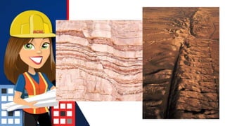
Faults are fractures on which
identifiable shear displacement has
taken place. They may be recognized
by the relative displacement of the
rock on opposite sides of the fault
plane.
Rock_p4_Rock Mass Characterization.pptx
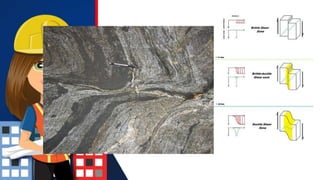
Shear zones are bands of material,
up to several meters thick, in which
local shear failure of the rock has
previously taken place. They
represent zones of stress relief in an
otherwise unaltered rock mass
throughout which they may occur
irregularly.
Rock_p4_Rock Mass Characterization.pptx
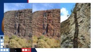
Dykes are long, narrow intrusions of
generally fine-grained igneous rock
with steep or vertical and
approximately parallel sides.
Rock_p4_Rock Mass Characterization.pptx
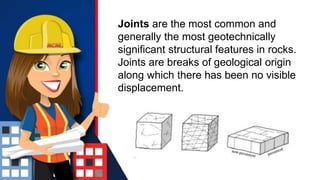
Joints are the most common and
generally the most geotechnically
significant structural features in rocks.
Joints are breaks of geological origin
along which there has been no visible
displacement.
Veins, or cemented joints, are mineral
infillings of joints or fissures. They may
be sheet-like or tabular or irregular.
Important Geomechanical
Properties of Discontinuities
Spacing is the perpendicular distance
between adjacent discontinuities, and
is usually expressed as the mean
spacing of a particular set of joints.
Persistence is the term used to
describe the areal extent or size of a
discontinuity within a plane. It can be
crudely quantified by observing the
trace lengths of discontinuities on
exposed surfaces.
Orientation, or the
attitude of a discontinuity
in space, is described by
the dip of the line of
maximum declination on
the discontinuity surface
measured from the
horizontal, and the dip
direction or azimuth of this
line, measured clockwise
from true north.
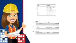
Roughness is a measure
of the inherent surface
unevenness and waviness
of the discontinuity relative
to its mean plane.
Rock_p4_Rock Mass Characterization.pptx
Aperture is the
perpendicular
distance separating
the adjacent rock
walls of an open
discontinuity in
which the
intervening space is
filled with air or
water.
Filling is the term used to describe
material separating the adjacent
rock walls of discontinuities.
Collecting Structural Data
Mapping Exposures
In the early stages of a mining project,
it may not be possible to gain access
underground. In this case, surface
outcrops must be utilised to obtain
information on the engineering
properties and structure of the rock
mass.
Approaches Used for Mapping
• spot mapping in which the observer
selectively samples only those
discontinuities that are considered to be
important;
• lineal mapping in which all discontinuities
intersecting a given sampling line are
mapped; and
• areal mapping in which all discontinuities
within a selected area of the face, often
called a window, are mapped.
Technique Used for Mapping
The basic technique used in mapping surface
or underground exposures is the scanline
survey. A scanline is a line set on the surface
of the rock mass, and the survey consists of
recording data for all discontinuities that
intersect the scanline along its length.
Geotechnical drilling and core
logging
Core drilling is the most reliable way of
exploring the interior of a rock mass prior to
mining. Downhole geophysical and other
instruments may be used in drill holes to
investigate the structure and physical
properties of the rock mass.
Presentation of Structural Data
Major structural features such as
dykes, faults, shear zones and
persistent joints may be depicted in a
variety of ways. Their traces may be
plotted directly on to mine plans with
the dips and dip directions marked.
Joints and bedding planes
The data for joints and bedding planes differ in
two significant respects from the data for
major structural features such as faults.
• They are much more numerous, giving rise
to a distribution of orientations for each set
rather than the single orientation used to
describe a major feature.
• Their spacing or frequencies are important
and must be represented in some way
Thank You ….

More Related Content

Rock_p4_Rock Mass Characterization.pptx

  • 1. Rock Mass Structure and Characterization BY: MARIA CARISSA M. LANDOY, RCE
  • 2. Rock material is the term used to describe the intact rock between discontinuities; it might be represented by a hand specimen or piece of drill core examined in the laboratory.
  • 3. Rock mass is the total in situ medium containing bedding planes, faults, joints, folds and other structural features.
  • 4. The nature and distribution of structural features within the rock mass is known as the rock structure.
  • 5. Major Types of Structural Features Bedding planes divide sedimentary rocks into beds or strata. They represent interruptions in the course of deposition of the rock mass.
  • 6. Folds are structures in which the attitudes of the beds are changed by flexure resulting from the application of post-depositional tectonic forces.
  • 9. Faults are fractures on which identifiable shear displacement has taken place. They may be recognized by the relative displacement of the rock on opposite sides of the fault plane.
  • 15. Shear zones are bands of material, up to several meters thick, in which local shear failure of the rock has previously taken place. They represent zones of stress relief in an otherwise unaltered rock mass throughout which they may occur irregularly.
  • 17. Dykes are long, narrow intrusions of generally fine-grained igneous rock with steep or vertical and approximately parallel sides.
  • 19. Joints are the most common and generally the most geotechnically significant structural features in rocks. Joints are breaks of geological origin along which there has been no visible displacement.
  • 20. Veins, or cemented joints, are mineral infillings of joints or fissures. They may be sheet-like or tabular or irregular.
  • 21. Important Geomechanical Properties of Discontinuities Spacing is the perpendicular distance between adjacent discontinuities, and is usually expressed as the mean spacing of a particular set of joints.
  • 22. Persistence is the term used to describe the areal extent or size of a discontinuity within a plane. It can be crudely quantified by observing the trace lengths of discontinuities on exposed surfaces.
  • 23. Orientation, or the attitude of a discontinuity in space, is described by the dip of the line of maximum declination on the discontinuity surface measured from the horizontal, and the dip direction or azimuth of this line, measured clockwise from true north.
  • 24. Roughness is a measure of the inherent surface unevenness and waviness of the discontinuity relative to its mean plane.
  • 27. Aperture is the perpendicular distance separating the adjacent rock walls of an open discontinuity in which the intervening space is filled with air or water.
  • 28. Filling is the term used to describe material separating the adjacent rock walls of discontinuities.
  • 29. Collecting Structural Data Mapping Exposures In the early stages of a mining project, it may not be possible to gain access underground. In this case, surface outcrops must be utilised to obtain information on the engineering properties and structure of the rock mass.
  • 30. Approaches Used for Mapping • spot mapping in which the observer selectively samples only those discontinuities that are considered to be important; • lineal mapping in which all discontinuities intersecting a given sampling line are mapped; and • areal mapping in which all discontinuities within a selected area of the face, often called a window, are mapped.
  • 31. Technique Used for Mapping The basic technique used in mapping surface or underground exposures is the scanline survey. A scanline is a line set on the surface of the rock mass, and the survey consists of recording data for all discontinuities that intersect the scanline along its length.
  • 32. Geotechnical drilling and core logging Core drilling is the most reliable way of exploring the interior of a rock mass prior to mining. Downhole geophysical and other instruments may be used in drill holes to investigate the structure and physical properties of the rock mass.
  • 33. Presentation of Structural Data Major structural features such as dykes, faults, shear zones and persistent joints may be depicted in a variety of ways. Their traces may be plotted directly on to mine plans with the dips and dip directions marked.
  • 34. Joints and bedding planes The data for joints and bedding planes differ in two significant respects from the data for major structural features such as faults. • They are much more numerous, giving rise to a distribution of orientations for each set rather than the single orientation used to describe a major feature. • Their spacing or frequencies are important and must be represented in some way