


ROTOR SPINNING PROCESS
- 1. MD. MAZBAH UDDIN BANGLADESH UNIVERSITY OF TEXTILES YARN ENGINEERING DEPARTMET BATCH 08 ROTOR SPINNING PROCESS
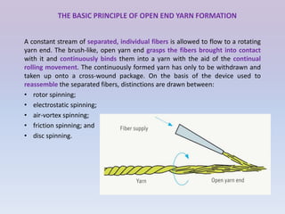
- 2. THE BASIC PRINCIPLE OF OPEN END YARN FORMATION A constant stream of separated, individual fibers is allowed to flow to a rotating yarn end. The brush-like, open yarn end grasps the fibers brought into contact with it and continuously binds them into a yarn with the aid of the continual rolling movement. The continuously formed yarn has only to be withdrawn and taken up onto a cross-wound package. On the basis of the device used to reassemble the separated fibers, distinctions are drawn between: • rotor spinning; • electrostatic spinning; • air-vortex spinning; • friction spinning; and • disc spinning.
- 3. Features of Rotor Spinning 1. Feed: Sliver (Carded/Drawn sliver) 2. Product: Rotor Yarn 3. Principle: Open End Spinning 4. Twisting Element: Rotor 5. Doubling: Back doubling 6. Both sided i.e. rotor head on both sides of the machine. 7. Advantage: Very High Production 8. Specialty: No need for Comber, Simplex, Autoconer 9. Drawback: Coarser Yarn No.
- 4. THE PRINCIPLE OF ROTOR SPINNING 1. Sliver feed: A card or draw frame sliver is fed through a sliver guide to a feed roller and feed table and which forwards to a rapidly rotating opening roller. 2. Sliver opening: The rotating teeth of the opening roller comb out the individual fibers from the sliver clamped between feed table and feed roller. After leaving the rotating opening roller, the fibers are fed to the fiber channel. 3. Fiber transport to the rotor: Centrifugal forces and vacuum in the rotor housing cause the fibers to disengage at a certain point from the opening roller and to move via the fiber channel to the inside wall of the rotor. 4. Fiber collection in the rotor groove: The centrifugal forces in the rapidly rotating rotor cause the fibers to move from the conical rotor wall toward the rotor groove and be collected there to form a fiber ring. 5. Yarn formation: When a spun yarn end emerges from the draw-off nozzle into the rotor groove, it receives twist from the rotation of the rotor outside the nozzle, which then continues in the yarn into the interior of the rotor. The yarn end rotates around its axis and continuously twists-in the fibers deposited in the rotor groove, assisted by the nozzle, which acts as a twist retaining element. 6. Yarn take-off, winding: The yarn formed in the rotor is continuously taken off by the delivery shaft and the pressure roller through the nozzle and the draw-off tube and wound onto a cross-wound package.
- 5. 1.Sliver 2.Feed roller 3.Feed trough 5. Opening roller 8.Feed tube/suction tube 18.Rotor groove 10.Free end 9.Rotor 16. Nozzle
- 6. THE ECONOMIC POTENTIAL OF ROTOR SPINNING • The economic advantages of rotor spinning very soon became evident and have increased in the course of its development with the result that its breakeven point has moved further in the direction of finer yarn counts. The following aspects are decisive in this respect: • Rotor spinning was the first process that was capable of producing a cross-wound package ready for processing or sale in a single process stage from a draw frame sliver. • Roving frames and winders could be dispensed with; there was thus a significant incentive from the very beginning to utilize this process, despite the higher cost of a rotor spinning position compared with a ring spinning position. • In terms of manufacturing costs per kg of rotor-spun yarn, direct labor costs occupied a position behind capital and energy costs. • Rotor spinning operates with very high efficiency, significantly above that of a ring spinning line. Machine efficiency of up to 99% is achieved in mill operations. • Stopping the machine to remove packages, as on ring spinning machines, does not occur in rotor spinning. • In many cases advantages in downstream processing in weaving and knitting mills result from longer, faultless running lengths on the cross-wound packages, i.e. fewer malfunctions and stoppages in the downstream process. • Last but not least, rotor spinning is more environmentally friendly in terms of dust and noise emissions compared with ring spinning, • its considerably higher output.
- 7. TECHNOLOGICAL SETTING PARAMETERS Fiber length Natural and man-made fibers up to 60 mm Sliver weight Nm 0.14 - 0.40; Ne 0.08 - 0.24; ktex 7.0 - 2.5 Yarn count range Nm 5 - 100; Ne 30 - 60; tex 200 - 10 Draft range 40 - 400-fold Twist range T/m 196 - 1 500/TPI 5 - 38 Winding helix adjustable between 30° and 40° in steps of
- 9. General specification Rotor speed No. of rotor Double sided Rotor dia Feed roller dia 60,000 – 120, 000 rpm 160-300 or more 32-38 mm or more 1-1.25 in Opening roller speed Opening roller dia 6 000 - 11 000 rpm 2-2.5 in Delivery speed, Draft Count range Package Numbers of rotors/section Number of robots Efficiency Winding angle 100-150m/min 100-300 5-10 Ne Cone, cheese, spool 20-24 Up to 4 90-100% 29-45 degree
- 10. Speed relationships • Normal and maximum revolutions and speeds are: • Revolutions of the opening roller: 5000- 11000 rpm • Revolutions of the rotor: up to or more than 100000rpm • Delivery speed up to 200 m/min
- 11. Tasks of the Rotor Spinning Machine: The basic tasks of the rotor spinning machine are: 1. Opening (& attenuating) almost to individual fibers (fiber separation). 2. Cleaning (optionally). 3. Homogenizing through back doubling. 4. Combining i.e. forming a coherent linear strand from individual fibers. 5. Ordering (the fibers in the strand must have an orientation as far as possible in the longitudinal direction). 6. Improving evenness through back-doubling. 7. Imparting strength by twisting 8. Winding.
- 12. Features of rotor spinning 1. It can process waste materials like short fibres, comber noil. i.e. excellent recycling machine. 2. Per rotor production is 4 – 10 times higher than ring spindle. 1. Bigger package like cheese – reduced doffing cost. 2. Lower fibre migration in rotor – uniform distribution of component fibres in blends. 3. Less irregularity. 4. Less hairiness of yarn. 5. Lower strength as compared to equivalent ring yarn .
- 13. Raw Material Used in Rotor Spinning: • There are three types of rotor spinning machine are distinguished according to fiber length: short, medium, long staple machine. Short staple spinning m/c (up to 60 mm fiber length) require: 1. Cotton (CO). 2. Cotton waste ( secondary m/t, e.g. from recycling). 3. Cotton noil. 4. Blends of two or more of these materials. 5. Polyester fibers (PES). 6. Polyacrylonitrile fiber ( PAC). 7. Poly amide fiber (PA). 8. Viscose (CV). 9. Blends of man-made fibers ( mostly PES/ CV & PAC/CV) 10. Blends of cotton & man made fibers ( mostly CO/ PES & CO/CV)
- 14. Raw Material Requirements: 1. Fiber Length: Following m/t can be processed according to Reiter Company Cotton fibers: 1. Waste <=7/8 inches ( for yarns up to 15 Ne count) 2. Short-staple cotton < =1 inch ( for yarns up to 18 Ne count ) 3. Medium staple cotton <= 1 1/8 inches (for yarn up to 35 Ne count ) Man made fibers:- 1. Staple length 32-40 mm (up to 60 mm ) for count 50 Ne
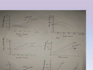
- 15. Fiber Length Continues • Cotton and cotton wastes with short fiber lengths can be processed very well by using the rotor spinning principle. But it should be borne in mind shorter the fiber worse the yarn quality. • Fiber length mainly influences yarn evenness and strength(increases with it usually). • Shorter fibers require more twists to get desired strength. But getting advantage from longer fibers depends on rotor dia. • if rotor dia is small for a given fiber length, then deposition of fibers on rotor groove is not adequately possible, which leads to increase of wrapping fibers. Hence, fiber length is not a dominating character in rotor spinning. Graphs: Fig: 43, 44
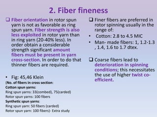
- 17. 2. Fiber fineness Finer fibers are preferred in rotor spinning usually in the range of: • Cotton: 2.8 to 4.5 MIC • Man- made fibers: 1, 1.2-1.3 , 1.4, 1.6 to 1.7 dtex. Coarse fibers lead to deterioration in spinning conditions; this necessitates the use of higher twist co- efficient. Fiber orientation in rotor spun yarn is not as favorable as ring spun yarn. Fiber strength is also less exploited in rotor yarn than in ring yarn (20-40% less). In order obtain a considerable strength significant amount fibers must be present in yarn cross-section. In order to do that thinner fibers are required. • Fig: 45,46 Klein (No. of fibers in cross section: Cotton spun yarns: Ring spun yarns: 33(combed), 75(carded) Rotor spun yarns: 100 fibers Synthetic spun yarns: Ring spun yarn: 50 fibers (carded) Rotor spun yarn: 100 fibers)- Extra study
- 19. 3. Fiber Strength • Due to poorer exploitation of the fiber substance, fibers of the greatest possible strength should be selected . Fig: 47,48 , Klein
- 21. 4. Dirt & Dust: • The rotor-spinning machine reacts very sensitively to the trash content of cotton. Coarse particles such as husk stay caught in the rotor groove. They can prevent yarn formation at this point, & this in turn can lead to an end down or to fiber agglomeration at the particle. This gives a thick place at the agglomeration point & immediately a thin place after this. The resulting thick and thin place are periodic and causes moiré effect if left in fabrics. • More trash content also lead to more neps generation. • Small particles also lead to deterioration in quality as these deposited in rotor groove, causing more open and voluminous yarn. Same also occurs when spin finishes of synthetic accumulate in rotor. • Clean raw m/t is therefore a precondition for spinning yarn on the rotor spinning m/c. Reiter recommended, the following residual trash content in the feed sliver: • Up to Ne 6 : 0.3% • Up to Ne20 : 0.2% • Up to Ne 30 : 0.15% • Up to Ne 50 : 0.10% • Fig: 49, 50
- 23. 5. Other Foreign Matter 1. Mineral dust: Quartz and mineral dust present in cotton works as sand paper and cause rapid wear on spinning elements such as opening roller, rotors, naval. 2. Honeydew: This forms sticky substance depositing on spinning elements causes spinning difficult. Resulting in inferior yarn quality and higher end breakage. 3. Spin finish for synthetic: Spin finishes rubbed off from fiber surface and accumulates on spinning elements causing same result as honeydew. 4. Delustrants: These are strongly abrasive like mineral dust and cause rapid wear. 5. Yarn remnants: When processing cotton waste from others machine such as ring machine, the unopened yarn pass into rotor and causes end breakage and thickplaces. - fig: 51
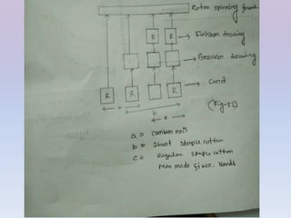
- 25. Preparation of raw material The manner in which raw materials are prepared in different rotor spinning stages is also important comparing to raw material characteristics. The process diagram of rotor spinning: fig-52 Blow room: Dirt and dust are disturbing factors in rotor. So a high cleaning effect is needed with a gentle fiber treatment. In blow room dust lying loosely is removed. Cards: the card usually removes 0.1-2% dirt content and also a part of the dust. The dust is rubbed off by fiber/metal friction. When card sliver is to be fed in rotor the sliver must be evener. Hence autolevelling attached to the card. Draw frames: D/F is used to remove dust and ensure higher sliver evenness as unevenness creates count variation. The draw frame also parallelizes fiber which leaders to better individualization of fibers by opener. Good coiling is also important so that loops ,knots and double slivers do not arise. Comber: combed cotton is not normally used in rotor spinning. But it is worth of a consideration as it removes SFC , neps and other impurities which are the cause significantly improving ring yarn quality.
- 27. 1.1A Opening device of rotor Infeed: The sliver runs from can through trumpet into the feed shoe. A diagonally fluted feed roller clamp the fibers evenly and forward sliver slowly into the operating zone of the opening roller in an optimum manner. If the yarn breaks the feed of the material cease by stopping the feed roller rotation or pivoting feed trumpet. Opening roller: The opening point is comparable with the infeed at the T-in of card , but the assembly is smaller. The teeth of the opener pass at high speed through the fiber beard being slowly pushed by the feed roller. By means of this continuous intensive combing operation, the opening roller carries along by friction all fibers emerging from the clamping nip between the feed shoe and feed roller. The projecting fiber beard takes on a wedge shaped form. Opener is contained in an assembly having three openings : 1. Sliver in feed 2. Fiber exit 3. Trash removal opening
- 29. 1.1B Intensive and even combing occurs 1. The thinner the sliver. 2. The more parallel the fiber arrangement.( two D/F passage are better than one) 3. The more highly straightened the fibers ( no crimp) 4. The more smoother the fibers (lustered or delustered) 5. Shorter the clamping distance. 6. High rotational speed of opener.
- 30. 1.1C Excessive speed of opener leads to 1. Tearing out of fiber bunches. 2. Fiber deterioration or even fiber damage. 3. Melt spots in processing synthetic fibers due to the heat generation by friction between fiber to metal . 4. Fiber buckling ( failure of removal from the clothing points) at the fiber-feed tube as peripheral speed of opener is greater than air speed in the suction tube. Also low rotational speed of opener leads to inferior yarn quality but also increase risk of lap formation.
- 31. Opening roller clothing • The opener rotates between 5,000 and 10,000 rpm, usually between 6,500-8,000 r/min. Higher rotational speed for higher throughput rate and vice versa. The diameter of opening roller lies between 60-80 mm. • The opener roller is subject to wear and therefore re-clothed or replace periodically, depending upon the wear rate. If delayed too long, yarn quality and spinning condition decline. • In processing synthetic fibers low tooth angle of rake is chosen for gentle fiber treatment. • For prevention of heat generation damage, it is recommended to use lower rotational speed, but high degree opening in that case is obtained by locating the clothing's closer at the feet to give higher point density.
- 33. 1.1D Opening roller clothing Clothing also exerts a great influence on the opening of fiber strand. This depends mainly on: 1. Type of clothing 2. The shape of the teeth 3. Teeth density. Fig: 56,55, 54 Clothing in opener depends upon: a)Type of fiber (raw material), b) fiber characteristics, c)the material throughput( coarse or fine). Types of clothing: 1. Metallic clothing: These are used in SSS because they are robust and have very good opening capability. 1. Needle clothing: This are limited to processing materials that don’t separate easily from clothing. Two types clothing have found wide acceptance and used in great majority: OS20: with an angle of attack of 25 degree for cotton ,viscose and blends of these materials OS21: with an angle of attack of 12 degree for synthetic fibers and all blends containing synthetic fibers.
- 34. 1.2 Trash removal at rotor All trash removing devices in rotor spinning machines are the same. Nothing more than a small or large opening in the opening roller housing. The higher speed of opener causes coarser trash particles to be got out from the assembly, while the fibers continue with the opener and sucked to the feed tube. Fig: 57, 58 Trash is carried away either: 1. Pneumatically , by suction extraction, or 2. Mechanically, by a small transport belt Trash removal intensity depends on: 1. Design of the assembly. 2. The airflow conditions 3. Degree of the opening in the feedstock 4. The speed of rotation of opener.
- 36. 1.3 Fiber guide passage(feed tube) to the rotor o After opening, the fibers must be passed to the rotor. For this purpose a tapered end suction or feed tube is used. Transport of fibers in this tube is done by an air flow, generated from the hermetically sealed rotor housing. o Fibers are guided directly onto the rotor wall for deposition in the rotor, while the air together with the large part of the dust flows over the rotor rim to opening. o The feed tube converges towards the rotor , which causes acceleration of the air and fiber flows. This acceleration further separate fibers( down to between 1 and 5 fibers in section) and also does some straightening. Fig: 59
- 37. Yarn Formation:1. Fiber flow in to rotor • Depending upon the arrangement of feed tube the fibers can move into rotor in two ways: Axially : Centrifugal force distributes the fibers within the rotor groove in purely random fashion and in accordance with umbrella principle. Defects of axial feed: 1. Fiber orientation in groove is bad. And yarn quality is also poor. 2. Larger rotor dia needed which limits rotor rev. 3. The spun yarn has to be withdrawn through rotor axis. Tangentially: This eradicates the problems of axial feed. Here rotation of rotor and corresponding air circulation within the rotor, ensure ordered deposition of fibers in the groove. • Fig: 60-61
- 39. Yarn Formation:2 formation of a coherent fiber strand At the early stage of rotor spinning development, the fibers were mistakenly guided directly into rotor collection groove. Which led to colliding of fibers with radial yarn end. Thus resulting in poor fiber orientation and to inferior yarn quality. But in modern machines, the fibers flowing to rotor strike directly onto the rotor wall above the rotor groove. But in this case it is vital that rotor wall has higher peripheral speed than fibers colliding with it. This also gives a drafting effect which ensures fiber straightening and lining up in order. The air flow is also vital in this region, there should not be any air turbulence between the feed tube and rotor wall. An incoming fiber strikes an inclined wall and is pressed outwards by an enormous centrifugal force over 100000 times the wt. of fiber. This causes the fiber to slide downwards on the rotor wall while being accelerated in peripheral direction and to be deposited on the other fibers in the collection groove.
- 40. Yarn formation:3Back doubling The process of yarn formation in rotor spinning involves the separation by an opening roller of a fiber bundle fed in, into individual fibers or small groups of fibers (no more than 5 fibers), which are then transported by the air current into the rotor, where they slide down the rotor wall. They are only combined again into fine layers of fibers in the rotor groove. A layer of these individual fibers is deposited in the rotor groove with each revolution of the rotor until the yarn reaches the required thickness. This building up of fiber layers to the final yarn thickness is described as back-doubling, with the number of fiber layers resulting from the (genuine) yarn twist set and the diameter/circumference of the rotor used. Back doubling= 𝑹𝒐𝒕𝒐𝒓 𝑺𝒑𝒆𝒆𝒅 𝑳𝒆𝒂𝒅 𝒐𝒇 𝒕𝒉𝒆 𝒚𝒂𝒓𝒏 𝒂𝒕 𝒔𝒆𝒑𝒆𝒓𝒂𝒕𝒊𝒐𝒏 𝒑𝒐𝒊𝒏𝒕(𝑳𝑷) Lead of the withdrawal Point= 𝒀𝒂𝒓𝒏 𝒘𝒊𝒕𝒉𝒅𝒓𝒘𝒂𝒍 𝒔𝒑𝒆𝒆𝒅) 𝑪𝒊𝒓𝒄𝒖𝒎𝒇𝒆𝒓𝒆𝒏𝒄𝒆 𝒐𝒇𝒕𝒉𝒆 𝒓𝒐𝒕𝒐𝒓 𝒈𝒓𝒐𝒐𝒗𝒆 Back doubling= 𝑹𝒐𝒕𝒐𝒓 𝒔𝒑𝒆𝒆𝒅 𝑹𝒐𝒕𝒐𝒓 𝒔𝒑𝒆𝒆𝒅 𝑻𝑷𝑴 𝒙 𝑹𝒐𝒕𝒐𝒓 𝒈𝒓𝒐𝒐𝒗𝒆 𝒄𝒆𝒓𝒄𝒖𝒎𝒇𝒆𝒓𝒆𝒏𝒄𝒆 =TPM x π x D (in meter) = 𝑻𝑷𝑴 𝒙 𝝅 𝒙 𝑫( 𝒊𝒏 𝒎𝒎) 𝟏𝟎𝟎𝟎
- 41. Wrapping fibers The rotor, and hence the fiber ring, revolve continuously under the stationary fiber channel – as also does the spun yarn end in the binding-in zone. A stream of individual fibers flows from the fiber channel and is deposited in the groove. Normally, incoming fibers land on fibers that have not yet been twisted in, but in the binding-in zone they strike an already-twisted yarn section rotating around its own axis. It cannot always be avoided that fibers arriving here wrap themselves around the yarn core in the form of a band called wrapping fibers. This is a typical characteristic, and simultaneously an identifying feature of rotor-spun yarns. The number of wrapping fibers increases, among other things, the longer the binding- in zone, the shorter the fibers relative to the rotor circumference and the higher the rotor speed. The wrapper fibers can be wound around the yarn in both the S and Z direction. In this aspect there is lower twist in outer fibers, this is the reason why the number of twists measured when determining yarn twist in the laboratory is usually lower than the required figure set on the machine.
- 43. No. of wrapping fiber depends on: 1. The position at which the fibers laid on the rotor wall. 2. The length of the binding-in- zone. 3. The ratio of fiber length to the rotor circumference. 4. The false twist level. 5. The rotor speed. 6. Fiber fineness. • Fig-65
- 44. Rotor Rotor is the main spinning element of the rotor spinning machine. Yarn quality, yarn character, working performance, productivity, costs etc. all depend chiefly on rotor. Influencing parameters of rotor: 1. The rotor form 2. The groove 3. The diameter 4. The rotational speed 5. The rotor bearing 6. Co-efficient of friction between the fiber and rotor wall. 7. The airflow inside the rotor 8. Liability to fouling. Fig:66, 67
- 45. Rotor groove The fibers pass finally into the rotor groove. Here the fiber strand of the yarn forms under the effect of back doubling. The yarn quality will be better , the more parallel, straight, and compactly the fibers are arranged in the strand. The groove has considerable influence on the yarn, depending on groove type, form, arrangement, finish etc. • The characteristics effected by the groove: 1. Compactness. 2. Hairiness. 3. Strength. 4. Handle. 5. Resistance to clumping of fibers under axially applied load. 6. The yarn twist level to be generated. 7. The groove effects the extent to which dust and dirt tend to be deposited in the rotor depending upon: 1. Material used. 2. Intended yarn characteristics. 3. Rotor dia and. 4. rotational speed.
- 47. Rotor diameter • The rotor dia mainly influences: 1. The character of the yarn. 2. The yarn properties. 3. The required yarn twist. 4. Selectable rotational speed. 5. Productivity. Basically the smaller rotor dia: 1. The higher are the possible and optimal rotational speeds. 2. The lower is the energy consumption. 3. The higher is the necessary yarn twist. 4. The harder is the handle. 5. The higher is the wrapping of fibers. 6. Larger dia for coarser yarn. Min dia=1.2 x SL
- 48. Rotor bearing The requirements of rotor bearing: 1. To be wear resistant. 2. To have long operating life. 3. To have low energy consumption. 4. To have low noise emission. 5. To have low heat generation. 6. To have ability to follow the drive. 7. To have uniformity of drive speed over time. 8. To be easily and quickly exchangeable.
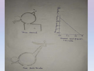
- 49. Rotor speed and rotor dia relation(rotor revolution) • Productivity and hence economics of the m/c are very dependent upon the rotational speed of rotor. Enormous efforts have been made to achieve greater rotational speed. Today higher than 100000 rpm is achieved. And a precondition to this speed was reduced diameter of the rotor. • As following relationship is found between the rotor dia and speed: Rotor Nmax= 𝟏𝟎 𝟔 𝒅 𝑹 𝒙 (𝟔𝑹) 𝟏/𝟐 Here, dR= rotor dia in mm R= exploitable breaking strength in cN/tex Nmax = max rotor rpm Fig: 72 And 73-77
- 52. Rotor Spinning vs Ring spinning system No Rotor Spinning frame No Ring Spinning frame 01 Rotor spinning frame is modern spinning system machine 01 Ring spinning frame is conventional spinning system machine 02 The working speed of rotor spinning frame is faster than ring spinning frame. 02 The working speed of ring spinning frame is lower than rotor spinning frame. 03 Usually rotor spinning frame produced lower count yarn. 03 This machine can produce from low count yarn to high count yarn. 04 Basically the raw material of this machine is low quality. Means low grade cotton. 04 Relatively this machine used high grade cotton to produce yarn. 05 Only one drafting system is available on this machine so there are no break draft in this machine. 05 Darting system is split in two divisions called main draft and break draft.
- 53. Rotor Spinning vs Ring spinning system 06 Twisting and winding process work separately in rotor spinning frame. 06 Twisting and winding process work with each other. 07 Production of rotor spinning frame is more than ring spinning frame. 07 Production of ring spinning frame is less than rotor spinning frame 08 Consumption of electricity is less 08 Consumption of electricity is more 09 The ratio of breakage yarn is less 09 The ratio of breakage yarn more 10 Production sound or noise is less 10 Production sound or noise of the machine is more t 11 The produced yarn package large. 11 The produced yarn package is small. 12 A few labor or technician can produce or maintain rotor spinning machine. 12 Ring spinning machine required more than ring spinning frame machine. 13 Rotor spinning frame produced balanced yarn. 13 Ring spinning frame produced less balanced yarn. 14 Trash less cotton is perfect for make yarn balanced so always used cotton should less trash cotton. 14 Comparability this machine can produce yarn from maximum amount of trash full cotton.
- 54. Rotor yarn vs ring yarnPhysical properties: 1. Breaking strength lower than ring spun Yarn. 2. CV% of strength better than ring spun yarn. 3. Elongation at break higher than ring spun yarn. 4. Mass irregularity ( over short lengths) better than ring spun yarn. 5. Imperfection index lower than ring spun yarn. 6. Volume greater than ring spun yarn. 7. Abrasion resistance higher than ring spun yarn. 8. Stiffness higher than ring spun yarn. 9. Handle harder. Aesthetic properties: – Surface rougher than ring yarn. – Hairiness lower than ring yarn. – Luster dull than ring yarn. In processing: 1. Tendency to form slubs greater. 2. Tendency to snarl lower. 3. Capacity to take up dye higher. 4. Resistance to abrasion better 5. Hairiness lower 6. Loop strength lower 7. Coefficient of friction higher See. 2.8.2.3/4
- 55. Differences in the end product Physical: 1. Breaking strength: somewhat lower. 2. Covering power higher 3. Abrasion resistance higher 4. Bending strength higher 5. Air permeability higher 6. Handle harder 7. Shrinkage slightly lower 8. Moisture take up higher Aesthetics: 1. Surface more evener 2. Pilling tendency low. 3. Hairiness low. 4. Luster duller.
- 56. Advantages & Disadvantages (Friction, open end) ADVANTAGES ARE AS FOLLOWS: • High delivery speeds. • Low yarn production costs (lower than those of ring spinning); • Elimination of rewinding. • Low end breakage rates. • Optically good mass evenness (well suited to knitted goods). • Yarn character similar to that of ring-spun yarn. • No wrapping fibers. • Better and softer handle than that of rotor-spun yarn. • Smooth yarn appearance. DISADVANTAGES ARE: • low yarn strength. • higher number of fibers needed in yarn cross-section. • high air consumption. • difficulty of keeping spinning conditions constant. • high tendency to snarl. • increasing unevenness and imperfections with increasing spinning speed, and further reduction in yarn strength.
- 57. Automation in rotor Systems for automating the operation of rotor spinning machines have been integral parts of high-performance rotor spinning machines for some years. Automated systems have been developed for all manual operations in several stages: 1. Automatic gripping and introduction of the sliver end from a new can into the spinning box. 2. Automatic cleaning of rotor, draw-off nozzle and draw-off tube after ends down, quality stops or package changes; 3. Automatic piecing (start-up) after ends down, quality stops or package changes; 4. Automatic removal of full packages(doffing) upon reaching the preset yarn length, and replacement with empty tubes. 5. Automatic feeding of empty tubes to the operating robot for package change; 6. Programmable batch phase-out/batch change; 7. Automatic deposit of removed packages at the end of the machine; 8. Automatic or semi-automatic filter cleaning. 9. Automatic yarn length measurement 10. Monitoring quality of individual yarn.
- 58. End Uses for Open End Spun Yarns Open end yarns produce different characteristics in the end product. These yarns may be used: 1. In fabrics where uniformity and a smoother surface are of prime importance. 2. Open end yarns are used in pile fabrics, apparel, household, industrial and technical applications. 3. Uses include heavy weight satin and poplins, corduroy, velveteen, rain wear, denims, drills, sheets, pillow cases, bed spreads, printed fabrics, curtains, window blinds, upholstery, cleaning cloths, dress goods, underwear, rugs, carpet, blankets, terry towel and diapers.
- 59. Additional: Math Calculate production. Assume all. No. of machine=12, heads per frame=360, rotor speed=100000 rpm, count=12, Tm= 4.5, efficiency=95%
- 60. Rotor cleaning • Dust particles lodged in the rotor groove generate moiré effects and increase the ends down rate. Dust deposition leading to filling of the groove and hence changes in yarn quality. • In a wide groove (a), a given no. of fibers in the yarn section occupy more space than a narrow groove (b) and hence the resulting yarn is open and voluminous. • When the groove is clean (d), the spun yarn is compact, as the groove becomes choked, the yarn becomes more(e) and more (f) open and voluminous because the groove is steadily rounded and broadened(D-F) • It is a gradual process, by the time is noticed , the damage is already done. Figure: Klein Ensuring rotor is kept clean: 1. Using clean feed stock 2. Attaining a high degree of cleaning in the preparatory stages 3. A trash removal position in rotor spinning m/c. 4. A rotor design giving a high degree of self-cleaning and 5. A rotor cleaning device.