


SDH ALARMS
- 1. NBP/RTTC-MYSORE NIRANJAN Regional Telecom Training Center MYSORE
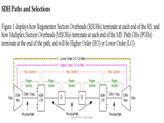
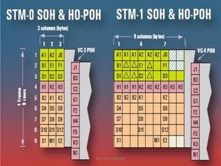
- 2. SDH Framing StructureSDH Framing Structure NBP/RTTC-MYSORE
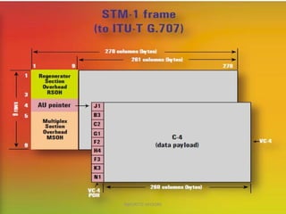
- 3. PP OO HH TUG-3TUG-3 TUG-3TUG-3 TUG-2TUG-2 TUG-2TUG-2 TU-12TU-12 TU-12TU-12 2 Mbit/s2 Mbit/s Stuff C-12C-12 Overhead (PDH) VC-12VC-12 Pointer (PTR) TU-12TU-12 TU-12TU-12 TU-12TU-12 TU-12TU-12 TUG-2TUG-2 TUG-2TUG-2 TUG-2TUG-2 TUG-2TUG-2 TUG-2TUG-2TUG-3TUG-3 VC-4VC-4 VC-4VC-4 MSOHMSOH AU PointerAU Pointer VC-4VC-4 SDH Framing Structure RSOHRSOH AU-4AU-4STM-1STM-1 NBP/RTTC-MYSORE
- 10. NBP/RTTC-MYSORE
- 11. NBP/RTTC-MYSORE
- 12. NBP/RTTC-MYSORE
- 13. NBP/RTTC-MYSORE
- 14. NBP/RTTC-MYSORE
- 15. NBP/RTTC-MYSORE
- 16. NBP/RTTC-MYSORE
- 17. NBP/RTTC-MYSORE
- 18. NBP/RTTC-MYSORE
- 19. NBP/RTTC-MYSORE
- 20. NBP/RTTC-MYSORE
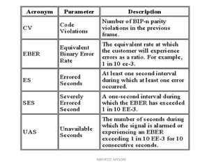
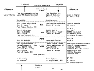
- 21. SDH ALARMS • LOS : When NE is unable to receive signal from other NE , due to fiber break , Tx failure of other NE,etc .It triggers Loss Of Signal • LOS is Physical Layer Alarm • There is no byte in SDH frame to indicate LOS. Its the transreceiver (SFP) which detects the in coming signal. • If no light coming to SFP it gives LOS to processor or the controlling device. Also when u get BER of orde 1 in 1000 results in LOS NBP/RTTC-MYSORE
- 22. LOS-Loss Of Signal AIS-Alarm Indication Signal RDI-Remote Defect Indication NBP/RTTC-MYSORE
- 23. Probable Causes ALARM PROBABLE CAUSE 1) STM -N Port loss of signal OF cable break Rx optical power beyond thrushhold limit (local eqpt) TX forced off (Forced Laser Off at distant end) Distant ADM/TM/REG module fault Distant end power failure Local RX faulty NBP/RTTC-MYSORE
- 24. SDH ALARMS • LOF : Assuming that signal is present . • Next job is to identify STM-1 frame by means of Nx 6 bytes FAW ( 3 bytes of A1 and 3bytesA2 bytes of RSOH) . • Else it triggers Loss Of Frame NBP/RTTC-MYSORE
- 25. NBP/RTTC-MYSORE
- 26. LOF-Loss Of Frame AIS-Alarm Indication Signal RDI-Remote Defect Indication NBP/RTTC-MYSORE
- 27. THE NEXT STEP IS TO FIND WHERE THE VC-4S ARE LOCATED RELATIVE TO THE FAW. THIS IS ESTABLISHED BY READING THE ADMIN UNIT (AU) POINTER TO LOCATE THE J1 BYTE IN THE VC-4 POH. IF A SENSIBLE POINTER CANNOT BE FOUND, A LOSS OF POINTER (LOP) ALARM IS RAISED AT THE AU LEVEL. THIS IS USUALLY REFERRED TO AS AN AU-LOP, AU-LOP NBP/RTTC-MYSORE
- 28. NBP/RTTC-MYSORE
- 30. TU-LOP The next step is to locate and read the Tributary Unit (TU) pointer for the specified TU. If a sensible pointer cannot be found, then a LOP alarm is raised at the TU level NBP/RTTC-MYSORE
- 31. NBP/RTTC-MYSORE
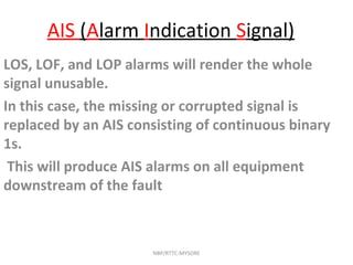
- 33. AIS (Alarm Indication Signal) LOS, LOF, and LOP alarms will render the whole signal unusable. In this case, the missing or corrupted signal is replaced by an AIS consisting of continuous binary 1s. This will produce AIS alarms on all equipment downstream of the fault NBP/RTTC-MYSORE
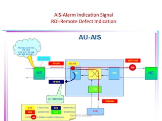
- 34. AIS-Alarm Indication Signal RDI-Remote Defect Indication NBP/RTTC-MYSORE
- 35. AIS-Alarm Indication Signal LOS-Loss Of Signal RDI-Remote Defect Indication NBP/RTTC-MYSORE
- 36. AIS-Alarm Indication Signal RDI-Remote Defect Indication NBP/RTTC-MYSORE
- 37. AIS-Alarm Indication Signal RDI-Remote Defect Indication NBP/RTTC-MYSORE
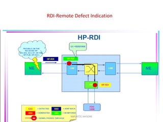
- 38. FERF- Far End Reporting Failure RAI-Remote Alarm Indication The NE detecting the fault also sends an indication to the distant (sending) end that an alarm has been raised. This raises a FERF alarm at the appropriate level at the transmitting NE. Thus, a fault at the MS level will produce an MS-FERF. At the VC-4 level, it will produce a VC-4 FERF on some equipment, HO-FERFs. Some SDH elements refer to a remote alarm indication at some levels in the hierarchy. NBP/RTTC-MYSORE
- 39. HO FERF- Far End Reporting Failure NBP/RTTC-MYSORE
- 40. LO FERF- Far End Reporting Failure NBP/RTTC-MYSORE
- 42. TIM-Trace Identifier Mismatch AIS-Alarm Indication Signal RDI-Remote Defect Indication NBP/RTTC-MYSORE
- 44. EXC-Excessive Bit Error rate( > 10x E-3) NBP/RTTC-MYSORE
- 55. EXC-Excessive Bit Error rate( > 10x E-3) NBP/RTTC-MYSORE
- 61. EXC-Excessive Bit Error rate( > 10x E-3) NBP/RTTC-MYSORE
- 64. LOM-Loss Of Multi frame NBP/RTTC-MYSORE
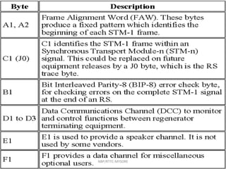
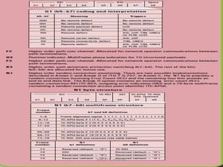
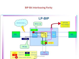
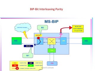
- 65. ERROR MONITORING NBP/RTTC-MYSORE B1 byte is used to check for errors in the RS. B2 byte is used to check for errors in the MS. B3 byte is used to check for errors in the VC-4 path. V5 byte is used to check for errors in the VC-12 path.
- 66. NBP/RTTC-MYSORE
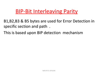
- 67. BIP-Bit Interleaving Parity B1,B2,B3 & B5 bytes are used for Error Detection in specific section and path . This is based upon BIP detection mechanism NBP/RTTC-MYSORE
- 68. NBP/RTTC-MYSORE
- 69. NBP/RTTC-MYSORE
- 70. NBP/RTTC-MYSORE
- 71. NBP/RTTC-MYSORE