Secador Regenerativo 0741 1500
•
0 likes•58 views

The document summarizes Heat-of-Compression (HOC) air dryers from Ingersoll-Rand. HOC dryers are the most energy efficient dryers that use recovered heat from air compression to dry the air. They provide dry air using virtually no energy. The H-Series dryer requires only 24 watts to power controls while the HC-Series provides extremely low dew points below -40°F through a stripping and cooling cycle. Both dryers minimize moisture problems and costs while maximizing reliability, productivity, and safety.
Report
Share


Secador Regenerativo 0741 1500
- 1. H & HC Heat-Of-Compression Air Dryers
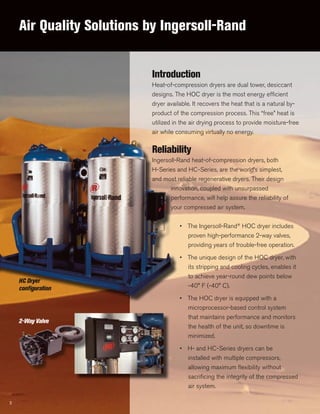
- 2. Air Quality Solutions by Ingersoll-Rand HC Dryer configuration Introduction Heat-of-compression dryers are dual tower, desiccant designs. The HOC dryer is the most energy efficient dryer available. It recovers the heat that is a natural by- product of the compression process. This “free” heat is utilized in the air drying process to provide moisture-free air while consuming virtually no energy. Reliability Ingersoll-Rand heat-of-compression dryers, both H-Series and HC-Series, are the world’s simplest, and most reliable regenerative dryers. Their design innovation, coupled with unsurpassed performance, will help assure the reliability of your compressed air system. • The Ingersoll-Rand® HOC dryer includes proven high-performance 2-way valves, providing years of trouble-free operation. • The unique design of the HOC dryer, with its stripping and cooling cycles, enables it to achieve year-round dew points below -40° F (-40° C). • The HOC dryer is equipped with a microprocessor-based control system that maintains performance and monitors the health of the unit, so downtime is minimized. • H- and HC-Series dryers can be installed with multiple compressors, allowing maximum flexibility without sacrificing the integrity of the compressed air system. 2 2-Way Valve
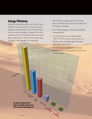
- 3. Heatless Refrigerated Externally Heated Blower Purge I-R HC-Series I-RH-Series Energy Costs Energy Efficiency Heat-of-compression dryers are the most cost- effective means to protect air lines, tools and expensive instrumentation. The H-Series dryer does not use any heaters or blowers. The only operating cost is for electricity needed to power the microprocessor controls, which is less than 24 watts – the equivalent of a light bulb. • The H-Series averages less than $10 per year in total electrical cost, because there are no heaters or blowers. • The H-Series design consumes no valuable compressed air. • The HC-Series can constantly provide -40° F (-40° C) or lower dew points, at a fraction of the cost associated with other regenerative type dryers. • The HOC dryer is designed to minimize pressure drop by utilizing full flow valves and minimal piping. No other compressed air dryer can deliver dry air at so low an annual operating cost 3
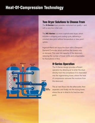
- 4. Heat-Of-Compression Technology 4 Two Dryer Solutions to Choose From The H-Series dryer provides instrument air quality – and with a very low initial cost. The HC-Series is a more sophisticated dryer, which includes a stripping and cooling cycle, delivering a constant dew point without temperature or dew point spikes. Ingersoll-Rand can equip the dryer with a Dewpoint Demand Controller which switches the towers only on demand. This uses full capacity of the desiccant, reducing the number of tower shifts and compensates for fluctuations in flow. H-Series Operation The H-Series design provides efficient operation by allowing air to enter the dryer directly from the compressor. It is channeled into the regenerating tower, where the heat of compression removes the moisture from the desiccant. The air next flows into the aftercooler, then separator, and finally into the drying tower, where the air is dried to its final low dew point. AFTERCOOLER LEFT TOWER OUTLET-Dry Air INLET-Hot Air RIGHT TOWER SEPARATOR NO LOSS DRAIN TRAP (Regenerating) (Drying)
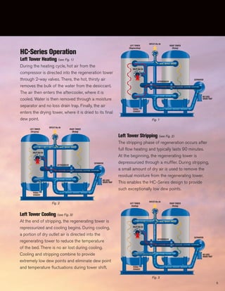
- 5. 5 HC-Series Operation Left Tower Heating (see Fig. 1) During the heating cycle, hot air from the compressor is directed into the regeneration tower through 2-way valves. There, the hot, thirsty air removes the bulk of the water from the desiccant. The air then enters the aftercooler, where it is cooled. Water is then removed through a moisture separator and no loss drain trap. Finally, the air enters the drying tower, where it is dried to its final dew point. Left Tower Stripping (see Fig. 2) The stripping phase of regeneration occurs after full flow heating and typically lasts 90 minutes. At the beginning, the regenerating tower is depressurized through a muffler. During stripping, a small amount of dry air is used to remove the residual moisture from the regenerating tower. This enables the HC-Series design to provide such exceptionally low dew points. Left Tower Cooling (see Fig. 3) At the end of stripping, the regenerating tower is repressurized and cooling begins. During cooling, a portion of dry outlet air is directed into the regenerating tower to reduce the temperature of the bed. There is no air lost during cooling. Cooling and stripping combine to provide extremely low dew points and eliminate dew point and temperature fluctuations during tower shift. AFTERCOOLER LEFT TOWER OUTLET-Dry Air INLET-Hot Air RIGHT TOWER SEPARATOR NO LOSS DRAIN TRAP PURGE EXHAUST (Regenerating) (Drying) AFTERCOOLER LEFT TOWER OUTLET-Dry Air INLET-Hot Air RIGHT TOWER SEPARATOR NO LOSS DRAIN TRAP PURGE EXHAUST (Stripping) (Drying)(Drying)(Drying) AFTERCOOLER LEFT TOWER OUTLET-Dry Air INLET-Hot Air RIGHT TOWER SEPARATOR NO LOSS DRAIN TRAP PURGE EXHAUST (Cooling) (Drying) Fig. 3 Fig. 1 Fig. 2
- 6. Productivity The problems created by moisture contamination in a compresser air system include rust and corrosion in the air piping, inadequate air tool lubrication, and damage to labeling, packaging and the finished goods. The HOC dryer can prevent such productivity losses throughout your operation by delivering a continuously low dewpoint. • The H-Series dryer can deliver points in the 0° F (-18° C) to -60° F (-51° C) range depending on the operating conditions. The H-Series dryer delivers better than instrument quality air to eliminate moisture problems. • With its patented stripping and cooling cycles, the HC-Series dryer can produce continuous year-round dew points of -40° F (-40° C) and below. • Both the H- and HC-Series dryers prevent costly production interruptions due to moisture contamination. Health, Safety and Environment Ingersoll-Rand HOC dryers are designed to protect the health and safety of the operators and the environment in which they are installed. • Dryers utilize a non-acidic desiccant and no ozone depleting refrigerants. • Insulated towers protect operators from hot surfaces. • The HOC dryer is a packaged design, with all components pre-piped and pre-wired. This eliminates costly installation charges and minimizes floor space requirements. 6
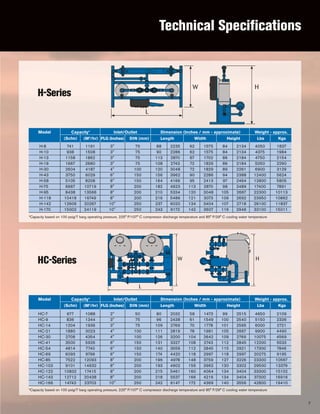
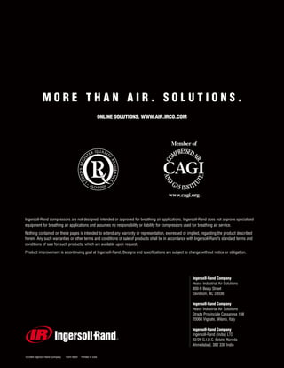
- 7. Technical Specifications Model Capacity* Inlet/Outlet Dimension (Inches / mm - approximate) Weight - approx. (Scfm) (M3 /hr) FLG (Inches) DIN (mm) Length Width Height Lbs Kgs L W H H-8 741 1191 3" 75 88 2235 62 1575 84 2134 4050 1837 H-10 938 1508 3" 75 90 2286 62 1575 84 2134 4375 1984 H-13 1158 1862 3" 75 113 2870 67 1702 86 2184 4750 2154 H-19 1667 2680 3" 75 108 2743 72 1829 86 2184 5050 2290 H-30 2604 4187 4" 100 120 3048 72 1829 89 2261 6900 3129 H-43 3750 6029 6" 150 156 3962 90 2286 94 2388 12400 5624 H-58 5105 8208 6" 150 164 4166 95 2413 97 2464 12800 5805 H-75 6667 10719 8" 200 182 4623 113 2870 98 2489 17400 7891 H-95 8438 13566 8" 200 210 5334 120 3048 105 2667 22300 10113 H-118 10418 16749 8" 200 216 5486 121 3073 106 2692 23950 10862 H-142 12606 20267 10" 250 237 6020 134 3404 107 2718 26100 11837 H-170 15002 24119 10" 250 243 6172 142 3607 116 2946 33100 15011 L W H Model Capacity* Inlet/Outlet Dimension (Inches / mm - approximate) Weight - approx. (Scfm) (M3 /hr) FLG (Inches) DIN (mm) Length Width Height Lbs Kgs HC-7 677 1088 2" 50 80 2032 58 1473 99 2515 4650 2109 HC-9 836 1344 3" 75 96 2438 61 1549 100 2540 5150 2336 HC-14 1204 1936 3" 75 109 2769 70 1778 101 2565 6000 2721 HC-21 1880 3023 4" 100 111 2819 78 1981 105 2667 9900 4490 HC-30 2708 4354 4" 100 126 3200 104 2642 109 2769 10075 4569 HC-41 3500 5926 6" 150 131 3327 108 2743 112 2845 12200 5533 HC-54 4814 7740 6" 150 140 3556 112 2845 115 2921 17300 7846 HC-69 6093 9796 6" 150 174 4420 118 2997 118 2997 20275 9195 HC-85 7522 12093 8" 200 196 4978 148 3759 127 3226 23300 10567 HC-103 9101 14632 8" 200 193 4902 156 3962 130 3302 29500 13379 HC-122 10832 17415 8" 200 215 5461 160 4064 134 3404 33300 15102 HC-143 12712 20438 8" 200 218 5537 166 4216 134 3404 37300 16916 HC-166 14743 23703 10" 250 242 6147 172 4369 140 3556 42800 19410 *Capacity based on 100 psig/7 barg operating pressure, 225° F/107° C compressor discharge temperature and 85° F/29° C cooling water temperature *Capacity based on 100 psig/7 barg operating pressure, 225° F/107° C compressor discharge temperature and 85° F/29° C cooling water temperature H-Series HC-Series 7
- 8. M O R E T H A N A I R . S O L U T I O N S . ONLINE SOLUTIONS: WWW.AIR.IRCO.COM © 2004 Ingersoll-Rand Company Form 8535 Printed in USA Ingersoll-Rand Company Heavy Industrial Air Solutions 800-B Beaty Street Davidson, NC 28036 Ingersoll-Rand Company Heavy Industrial Air Solutions Strada Provinciale Cassanese 108 20060 Vignate, Milano, Italy Ingersoll-Rand Company Ingersoll-Rand (India) LTD 22/29 G.I.D.C. Estate, Naroda Ahmedabad, 382 330 India Ingersoll-Rand compressors are not designed, intended or approved for breathing air applications. Ingersoll-Rand does not approve specialized equipment for breathing air applications and assumes no responsibility or liability for compressors used for breathing air service. Nothing contained on these pages is intended to extend any warranty or representation, expressed or implied, regarding the product described herein. Any such warranties or other terms and conditions of sale of products shall be in accordance with Ingersoll-Rand’s standard terms and conditions of sale for such products, which are available upon request. Product improvement is a continuing goal at Ingersoll-Rand. Designs and specifications are subject to change without notice or obligation. Member of www.cagi.org