Location via proxy:   [ UP ]  
[Report a bug]   [Manage cookies]                
SlideShare a Scribd company logo
The
Complete
VisualGuideto
Building
a House
John Carroll and Chuck Lockhart
The
Complete
VisualGuideto
Building
a House
The Complete Visual Guide To Building A House.pdf
The
Complete
VisualGuideto
Building
a House
C
John Carroll and Chuck Lockhart
Text © 2013 by The Taunton Press, Inc.
Illustrations © 2013 by The Taunton Press, Inc.
All rights reserved.
Pp
The Taunton Press, Inc., 63 South Main Street, PO Box 5506, Newtown, CT 06470-5506
e-mail: tp@taunton.com
Editors: Peter Chapman, Scott Gibson
Copy editor: Diane sinitsky
Indexer: jim curtis
Jacket/Cover design: jean-marc Trodaec
Interior design: carol singer | notice design
Layout: Cathy Cassidy, chuck lockhart
Illustrator: chuck lockhart
The following names/manufacturers appearing in The Complete Visual Guide to Building a House
are trademarks: Backer-On™; C. H. Hanson® Pivot Square™; CavClear®; Cor-A-Vent®; Dap® Presto Patch®; Deck-
Armor™; Delta®-MS; DensShield®; DrainWrap™; DuPont StraightFlash™; DuPont™ FlexWrap™; Durock®; Festool®;
FoamSealR™; HardieBacker®; Home Slicker®; Ice & Water Shield®; Jambsill Guard®; Level-Best®; McFeely’s®;
MortarNet®; Osmose®; Porter-Cable®; RainDrop®; RockRipper®; Roofer’s Select™; Schluter®-DITRA; Sheetrock®;
Shingle Mate®; Simpson Strong-Tie®; Stanley® Quick Square®; StormGuard®; Super ThoroSeal®; Sure-Tite™;
SureCorner™; SureSill™ HeadFlash™ and HeadFlash-Flex™; Swanson® Big 12® Speed® Square; T-JAK®; Tapcon®;
Telpro® Panellift®; Timberline®; Titanium® 30; Typar®; Tyvek® StuccoWrap®; Warm-N-Dri®; Warner® Tool;
WaterWay™; Weathermate™ Sill Pan; WeatherTrek®; WinterGuard™; Wolman™; WonderBoard®
Library of Congress Cataloging-in-Publication Data
Carroll, John (John Michael), 1949-
The complete visual guide to building a house / John Carroll and Chuck Lockhart.
pages cm
Includes index.
E-Book ISBN 978-1-62710-608-5
1. House construction--Handbooks, manuals, etc. 2. House construction--Pictorial works. I. Lockhart, Chuck. II. Title.
TH4813.C37 2014
690’.837--dc23
2013048589
Printed in the United States of America
10 9 8 7 6 5 4 3 2 1
About Your Safety: Construction is inherently dangerous. Using hand or power tools improperly or
ignoring safety practices can lead to permanent injury or even death. Don’t try to perform operations
you learn about here (or elsewhere) unless you’re certain they are safe for you. If something about an
operation doesn’t feel right, don’t do it. Look for another way. We want you to enjoy working on your
home, so please keep safety foremost in your mind.
For my mother, Emily J. Carroll (1923–2012)
The idea for this book came from Steve Culpepper, who, at the
time, served as executive book editor for The Taunton Press. In looking at the
available general guides to residential building, Steve found that most were
several decades old and contained outdated information. He felt there was a
need for a reference that reflected today’s building industry, and, to my good
fortune, he thought I should be the one to write it.
Shortly after I started writing this book, however, Steve left Taunton and
Peter Chapman took over as book editor. In addition to all his other duties,
Peter served as the primary editor of this book. Peter’s help proved to be
invaluable. I am especially grateful for his forbearance with me as a writer
whose “cup runneth over” on a regular basis. In chapter after chapter, I sub-
mitted too many words and too much information, so Peter would patiently
work with me to pare the text down to a manageable size. With Peter’s help, I
was able to identify the essential information and present it in a much more
concise manner. His insights and suggestions made this book shorter, clearer,
and better organized.
My in-depth discussion of common building procedures would be confus-
ing without accompanying drawings. To graphically represent what I’ve
described, The Taunton Press brought in one of the finest illustrators in the
business, Chuck Lockhart. Having worked as art director for Fine Homebuilding
magazine for 18 years, Chuck brought a wealth of experience to this project.
His drawings are more extensive and provide more detail than would have
been possible with photographs, which require access to building projects at
key moments in the job. Anything I could describe Chuck could draw. Chuck
was able to highlight key details through the use of color and shading; in
many drawings, Chuck skillfully employed such devices as cutaway views and
cross-sectional drawings to show how the details of the job fit into the whole.
After all the parts of this book were produced, the unenviable task of
putting them together fell to Scott Gibson. A skilled carpenter and an accom-
plished writer and editor, Scott went through every word of text and every
drawing. In addition to looking for and finding mistakes, inconsistencies, and
omissions, Scott extracted information from the running text and applied it,
in the form of labels, to the drawings. His painstaking attention to detail,
his focus on accuracy, and his knowledge of current building practices—
especially the latest in building science—were extremely helpful and greatly
improved the quality of this book.
—John Carroll
ACKNOWLEDGMENTS
Building the Structure	 4
	 Chapter 1
	 Building Foundations	6
	Chapter 2
	 Framing Floors, Walls, and Ceilings	 50
	Chapter 3
	 Framing Roofs 1: Raftered Roofs	 98
	 Chapter 4
	 Framing Roofs 2: Trusses, Eaves, Rakes,
	 and Sheathing	142
	 Closing the House to the Weather	 182
	Chapter 5
	 Roofing the House	184
	 Chapter 6
	 Installing Windows, Exterior Doors,
	 Siding, and Trim	 231
	Chapter 7
	 Controlling Moisture in the Ground
	 and in the Air	278
	
pa r t tw o
pa r t o n e
	 introduction
table of contents
Finishing the House	 308
	 Chapter 8
	 Installing Wall and Floor Coverings	 310
	Chapter 9
	 Hanging Doors	354
	Chapter 10
	 Installing Trim and Cabinets	 396
	Chapter 11
	 Building Stairs	442
	appendices
	 Conversions	 500
	Base-1 Proportions of Standard Roof Pitches	 501
	Backing Angles for Regular Hips and Valleys	 502
	Base-1 Proportions of Regular Hips and Valley Pitches	 503
	Converting X-in-12 Roof Pitch to Degrees of an Angle	 504
	Converting X-in-16.97 Roof Pitch to Degrees	 505
	Miter and Bevel Settings for Crown Molding	 506
	Index	 514
pa r t t h r ee
2	
In America, houses are built in areas where several feet of
snow accumulate, where hurricanes can be expected, or where tempera-
tures exceed 100°F. In some areas, all these conditions might occur within
the same year. Within these very different climatic regions, furthermore,
individual building sites pose a wide variety of challenges. The surface of
the land might slope steeply; the soil might contain expansive clay or bed-
rock; or there might be too much moisture in the ground.
To meet these and other challenges, builders have to adjust the design
of their houses to the climatic and topographical conditions of the area
they live in. In Florida, for example, roof structures must be tied down
with steel straps to keep them from being lifted off the walls during hur-
ricanes. In Maine, on the other hand, roof frames must be beefed up to keep
them from collapsing under the weight of several feet of snow. These mea-
sures, which are required by building codes, go a long way toward creating
durable houses.
Beyond simply building houses that last, however, builders need
to create houses that perform. Once viewed as basic shelters from the
extremes of the weather, houses are now seen as climate-controlled
enclaves. Most people expect the environment inside their house to be
comfortable year-round, no matter how brutal the weather is outside.
Accomplishing this goal in the face of ever-increasing energy costs is one of
the biggest challenges confronting builders today. Again, the plan of attack
has to be tailored to the location of the house. A house that keeps a family
warm during the winter on the Northern Plains has to be built much differ-
ently than a house that provides relief from the heat and humidity in the
Deep South.
The diverse local requirements of home building coupled with an
ever-expanding choice of building materials, tools, and systems present a
fundamental problem for a book like this one. Because there are so many
approaches and options, it’s difficult to decide what to discuss and how
detailed that discussion should be. As on any major building project, there
have been many hard decisions to make and there have been many inter-
esting and worthwhile topics that I could not include in this book.
introduction
The first thing I decided to drop was a comparative analysis of different
building systems. There are at least a half-dozen alternatives to the light
wood-framed house in America. However, builders and homeowners con-
tinue to vote with their wallets for the wood-framed house, which accounts
for 90% of the houses in the United States and Canada. Rather than devote
a good portion of this book to a discussion of the strengths and weaknesses
of the other systems, I chose to focus on the one system that dominates the
housing market: the wood-framed house.
Along the same lines, I’ve focused on mainstream materials when
describing the rest of the house. In the chapter on foundations, for example,
I concentrated on concrete and masonry, and in the chapter on roofing,
I focused on asphalt shingles because most houses in America are built
with those materials. If you happen to use materials that are outside of the
mainstream, there’s a good chance that the installation techniques pre-
sented here will work, with minor adjustments, with the materials you use.
I’ve also focused on common building projects and designs. Throughout
the book, I posed hypothetical building projects and then suggested ways
to build them. In these projects, the rectangle predominated—just as it
does on most residential building sites. In general, I have steered clear of
complex designs, such as octangular buildings and curved staircases—both
because they couldn’t be covered adequately in the space allotted and
because they are rare in American houses.
Sticking with common design elements and mainstream materials has
allowed me to go into considerable detail when describing building tech-
niques. These details are often vital to the quality of the job, and builders
who overlook them or try to force them in as an afterthought usually end
up with substandard work. Throughout this book, therefore, I’ve hammered
home the idea that quality work requires two things: forethought and the
proper sequence of installation. It’s essential to think through the details at
the beginning of the job and then install them at just the right moment.
No book, including this one, can provide every important detail for every
job. What I’ve tried to do here is show how to look at the job, anticipate
problems, and then work in the optimal sequence to fit the parts together
smoothly and correctly. Learn these lessons well and you’ll find it easy to
progress to more complex jobs.
	introduction	 3
4
6
50
98
142
5
PA r t 	 o n e
Building	the	structure
C H A P T E R 1
Building	Foundations
C H A P T E R 2
Framing	Floors,	Walls,	and	Ceilings
C H A P T E R 3
Framing	Roofs	1:	Raftered	Roofs
C H A P T E R 4
Framing	Roofs	2:	Trusses,	Eaves,	
Rakes,	and	Sheathing
6
1
CHAPTER
Building	
foundations
the	foundAtion	of	A	house	serves	two	basic	
functions.	First,	it	protects	the	rest	of	the	house	from	the	
harmful	effects	of	the	soil.	By	holding	the	frame	of	the	
house	up	off	the	ground,	the	foundation	keeps	it	a	safe	
distance	from	the	moisture,	frost,	termites,	mildew,	
rot-producing	fungi,	and	other	organisms	that	live	in	
the	ground.	
Second,	the	foundation	serves	as	a	transition	from	
the	irregular	surface	of	the	land	to	the	level,	plumb,	and	
square	surfaces	of	the	house.	Before	the	foundation,	
there	is	nothing	but	dirt;	after	the	foundation,	there	
should	be	a	square	and	plumb	structure	with	a	level	top.	
It	is	upon	this	fl
	at	and	even	surface	that	the	carpenters	
begin	the	frame	of	the	house.	
This	chapter	deals	with	the	challenge	of	building	a	
foundation	that	is	strong	enough	to	carry	the	weight	of	
the	entire	house;	tough	enough	to	endure	decades	of	
direct	contact	with	the	ground;	and	precise	enough	to	
use	as	a	fi
	rst	reference	for	building	the	rest	of	the	house.
frAMing	floors,	wAlls,	And	ceilings 7
2
Assessing	and	Preparing	the	soil
The	loads	that	houses	place	on	soils	are,	by	engineering	standards,	
relatively	light.	Most	building	codes,	furthermore,	are	conservative	in	
design.	They	require	wide	footings	that	spread	the	load	of	the	house,	
allowing	the	footings	to	work	in	soil	that	is	not	ideal.	If	you	carefully	
follow	the	provisions	of	the	building	code,	the	soil	you	encounter	on	
site	is	usually	capable	of	supporting	the	house	or	addition	that	you	
are	building.
However,	problem	soils	do	exist	and	they	require	measures	that	
go	beyond	the	general	provisions	in	the	building	code.	Foundations	
that	settle	unevenly	create	out-of-level	fl
	oors	and	doors	that	don’t	
open	and	close	properly.	
what	to	look	for	in	the	soil
There	are	a	few	things	you	can	do	to	determine	if	you	need	to	bring	
in	a	soils	engineer.	The	fi
	rst	is	to	look	carefully	at	the	soil.	Keep	an	
eye	on	how	the	soil	behaves	under	load,	especially	after	it	rains.	
These	are	commonsense	observations.	If	the	soil	becomes	soft	and	
mushy	underfoot	and	trucks	and	equipment	frequently	get	mired	in	
it,	you	might	have	a	problem.
Excavating for the foundation		The	most	important	person	to	
look	to	for	advice	is	your	building	inspector.	Building	offi
	cials	are	
usually	familiar	with	the	problem	soils	in	their	areas	and	often	know	
where	they	are	most	likely	to	occur.	They	can	sometimes	recognize	
problem	soils	simply	by	looking	at	them.
In some extreme cases, houses have
been ruined beyond repair by failed
foundations.
Most problem soils are classified as
clay or silt or a combination thereof.
The inorganic particles in these soils
are very fine—less than 0.003 in. in
diameter. When combined with water,
clays often become sticky or mushy.
When silts dry, they become fluffy;
they are sometimes called rock flour.
Coarse sand and rocky soils have
excellent load-bearing abilities. If you
encounter these soils, however, you
need to make sure that they are con-
sistent over the length of the footing.
Good, stable soils next to unstable
soils can translate into differential
movement.
1
Preparing the Soil
If you encounter problem soil
and are required to bring in
an engineer, make sure you
understand what the engi-
neer recommends and follow
those recommendations to the
letter. If you and the building
inspector find the soil accept-
able, you need to follow the
requirements of the building
code in your area.
toP	tiP
1
8 Building	the	structure
Monolithic slab: Simply scrape any
organic matter off the surface. The
bottom should be roughly level.
Crawlspace: Scrape any organic
matter off the surface but leave
the grade roughly the same as you
found it.
Basement excavations: It’s important
not to go too deep when you dig
these foundations.
excavation:	An	overview
If	you’re	building	a	basement,	the	excavation	consists	of	an	open-
ing	in	the	ground	with	a	roughly	level	bottom.	This	opening	has	to	
be	a	few	feet	wider	and	longer	than	the	house.	The	correct	elevation	
of	the	bottom	of	the	opening	should	be	determined	in	advance	as	
outlined	in	the	section	on	foundation	layout	on	p.	11.	As	the	exca-
vator	gets	down	close	to	this	elevation,	you	should	start	checking	
the	elevation	of	the	bottom	of	the	opening.	At	the	same	time,	check	
the	bottom	for	levelness.	The	techniques	for	measuring	the	eleva-
tion	and	the	levelness	of	the	bottom	of	the	opening	are	discussed	in	
detail	in	the	section	on	p.	11	on	foundation	layout.
STEP 1 excavating	for	the	foundation
Proposed foundation
STEP 2 digging	the	footings
1 Building codes require that the bottom of the footing
be below the frost line. Wet soil that freezes expands as
much as 8%. As it expands, it rises and lifts whatever is on
it, including the footings of houses. To avoid frost heave,
as it’s called, you are required to place the footing below
the frost line (the depth to which the ground freezes).
This means that in Maine it’s often necessary to dig down
48 in. or more, while in Florida a trench 8 in. deep is often
sufficient for the footing.
The frost line in Maine is 48 in. The frost line in Florida is 8 in.
1
2 It’s important to make sure that no sizeable amounts of organic matter
remain in the soil after the excavation. Make sure that the footing rests on
well-compacted soil. The simplest and surest way to do this is to place the con-
crete on undisturbed soil. Digging into undisturbed soil loosens it and fluffs it
up by as much as 50%. If this disturbed soil is left loose under the footing, the
weight of the house eventually compresses it back to its original size. When it
does, the footing often cracks.
Remove any
organic matter that
extends below the
proposed excavation.
Undisturbed soil
Disturbed soil
wAy s 	 o f 	w o r k i n g
Testing the Soil
One unscientific way to test the load-bearing capacity of
the soil is to push a steel stake into the ground. Building
inspectors often have a T-shaped tool made out of
½-in.-dia. steel rod. To test the soil prior to a footing
pour, the inspector leans on the cross of the T and sees
how far the upright sinks into the ground. If the steel
rod slides into the soil with little resistance, the inspector
will require remedial work.
A more objective way to test the soil under the foot-
ing is with a penetrometer. A penetrometer is a handheld
device that works like a fisherman’s scale in reverse. You
push the penetrometer in the soil and check the pressure
on a calibrated scale. Look for consistent readings along
the length of the footing and a bearing value that meets
the design load in your area (usually 1,500 lb. to 2,500 lb.
per square foot). For soil found to be below that bearing
capacity, most jurisdictions require a plan drawn up by
an engineer.
Steel stake
Penetrometer
	 Building	foundAtions 9
10 Building	the	structure 	
5 Footings spread the load they carry over a broad area. If
the weight of the building is concentrated on the edge of
the footing, however, it can cause the footing to rotate—just
as stepping on the edge of a snowshoe set on top of freshly
fallen snow would cause it to tip over.
3 To avoid the problems caused by disturbed soil in the
footing, clean loose material out of the footing trench
with hand tools (square shovels, mattocks, and hoes,
for example).
Wall centered over footing
4 Use a jumping jack compactor to reconsolidate the soil,
especially in those spots where tree stumps or large rocks
have been removed.
For clay or silt, add
sand or gravel to the
original soil as you
reconsolidate the area.
Dampen the mixture
and place it in 8-in.-
deep or less layers as
you compact it.
Off-center wall
have been removed.
For clay or silt, add
sand or gravel to the
original soil as you
reconsolidate the area.
Dampen the mixture
and place it in 8-in.-
deep or less layers as
you compact it.
An off-center footing
placed on soils with
relatively low bearing
capacity (clay, silt) can
fail.
frAMing	floors,	wAlls,	And	ceilings 11
1
laying	out	foundations
The	general	pattern	for	foundation	layout	is	from	the	top	down.	
The	process	begins	on	the	ground,	where	there	are	no	straight	lines,	
no	level	surfaces,	and	no	square	corners.	It’s	up	to	you	to	create	these	
references	from	scratch.	The	fi
	rst	step	in	this	process	is	to	set	up	a	
leveling	instrument	to	project	a	level	plane	above	the	ground.	From	
this	level	plane,	you	establish	the	elevation	of	the	top	of	the	founda-
tion.	All	subsequent	elevations	are	then	measured	down	from	this	
top-of-foundation	elevation.
At	the	top-of-foundation	elevation,	you	can	install	several	batter	
boards	that	hold	strings	within	a	level	plane	at	that	height.	You	can	
then	use	the	strings	to	precisely	lay	out	the	positions	of	the	footings	
and	foundation	walls	in	plan	view.	On	some	foundations,	however,	
it’s	easier	to	excavate	the	opening	for	the	house,	then	drop	down	to	
the	top-of-footing	elevation.	At	that	elevation,	you	can	use	a	combi-
nation	of	batter	boards	and	forms	to	lay	out	the	precise	positions	of	
the	footings	and	walls.
Whether you lay out the footing	and	walls	at	the	top-of-
foundation	elevation	or	at	the	top-of-footing	level,	the	layout	is	
suspended	above	the	ground.	It	has	to	be	this	way	for	two	reasons.	
First,	the	suspended	layout	establishes	the	exact	elevations	of	the	
key	components	of	the	foundation.	Second,	the	fl
	at,	level	plane	
ensures	that	the	key	parts	of	the	foundation	are	the	right	size	and	in	
the	right	place.	You	can’t	execute	a	precise	layout	on	the	ground;	the	
sloped	and	uneven	surface	will	distort	the	dimensions	and	render	
them	inexact.
The	following	section	uses	two	examples	to	show	how	to	lay	out	
two	different	kinds	of	foundations.	The	designs	presented	here	are	
common;	however,	some	of	the	details	might	not	be	accepted	where	
you	live.	Check	with	your	local	building	offi
	cials	to	fi
	nd	out	what’s	
needed	in	your	area.	Although	specifi
	c	examples	are	used	here,	the	
basic	procedures	can	be	adapted	to	just	about	any	foundation.
It’s Essential Not to
Overexcavate
Digging too deep, then put-
ting dirt back in the opening
compromises the integrity of
the soil under the footings. To
avoid overexcavating, check
the bottom of the opening
with increasing frequency as
you get closer to the desired
elevation.
toP	tiP
Leveling instrument Top of foundation
12 Building	the	structure 	
Approximately 30 ft.
Corner stake
Approximately 38 ft.
Getting the Grade Right
For the final grade around a house, most building codes
require that at least 8 in. of the foundation extend out
of the ground and that the soil slope away from the
foundation a minimum of 6 in. within the first 10 ft. To
achieve this minimum standard on the uphill side of the
foundation, measure the elevation 10 ft. uphill from the
planned foundation wall and set the elevation of the top
of the foundation at least 14 in. higher than the eleva-
tion at that point. Later, when you backfill around the
foundation, you’ll have enough elevation to form the
required grade on the uphill side. Leaving the founda-
tion higher than this minimum standard allows you to
increase the grade and hold the house up even higher
out of the ground.
laying	out	a	Basement	foundation
In	this	example,	the	foundation	is	a	38-ft.	by	30-ft.	basement	that	projects	about	30	in.	
above	the	highest	point	of	the	surrounding	grade.	The	corners	of	the	house	have	been	
roughly	marked	with	stakes	and	the	elevation	established	as	30	in.	above	one	of	the	
stakes.	The	fi
	rst	thing	you	have	to	do	is	guide	the	excavator	through	the	excavation	
of	the	opening	for	the	foundation.	In	this	phase	of	the	layout,	make	sure	the	excavator	
digs	in	the	right	place,	gets	the	opening	the	correct	size,	and	makes	the	bottom	level	
and	at	the	correct	height.	It	is	upon	the	roughly	level	surface	at	the	bottom	of	the	
excavation	that	you’ll	lay	out	the	footing	and	the	foundation	walls.
8 in. (min.) 6-in. (min.) slope 14 in. (min.)
Top of
foundation
10 ft.
wAy s 	 o f 	w o r k i n g
frAMing	floors,	wAlls,	And	ceilings 13
1
2 Record the elevation of the foundation. In this case, the desired elevation
for the top of the foundation is 30 in. above the highest corner stake. Using a
leveling instrument, measure the difference in elevation between the top of
the corner stake and the top of the nearest offset stake. (See “Using a Leveling
Instrument” on p. 14.)
Place the offset stakes 10 ft. from
the original corner stakes. Drive
offset stakes deep into the ground
so that very little extends above
the surface.
Original corner stakes
Approximately 30 ft.
Approximately 38 ft.
In this example, the bench mark stake
is 6 in. higher than the corner stake.
Bench mark
Corner stake
The top of the foundation, therefore, should be
24 in. above the top of the bench mark stake.
The top of the foundation is
30 in. above the corner stake.
STEP 1 record	the	preliminary	layout
1 When the excavator digs the oversized opening for the basement, the stakes
marking the corners of the house will be obliterated. To preserve the layout,
set up a line that extends over the corners of the house, then drive offset
stakes into the ground along that line. Place the offset stakes a set distance
away from the original corner stakes. A 10-ft. offset is common because it’s a
safe distance away from the excavation and it’s an easy distance to remember.
The offset stakes should be in line with the long walls (the 38-ft. walls, in
this example).
Flag the location of the
offset stakes with nearby
stakes that extend 16 in.
aboveground; attach
brightly colored ribbons.
14 Building	the	structure 	
Using a Leveling Instrument
There are two basic kinds of leveling instruments commonly used by builders:
optical levels (also called sight or telescopic levels) and laser levels. Both of
these kinds of levels come in many forms and are capable of doing numerous
measuring tasks. They share one feature in common, however; they all project
a level line and a level plane. For most residential builders, this basic feature is
the most important role of these tools.
An optical tool provides a level line of
sight. Swiveling the tool horizontally
establishes a level plane.
• MEASURING TO THE LEVEL PLANE
You can measure the grade of the land, establish the
elevation of key foundation components, set forms pre-
cisely level, and do many other layout tasks by measuring
to the level plane projected by a leveling instrument.
A laser level that projects a single
level line works the same way as
an optical level; swiveling it
establishes a level plane.
• ESTABLISHING A LEVEL PLANE
Different leveling instruments project a level plane in
different ways.
Lasers can also project a
level plane that radiates
in all directions from the
instrument.
Most leveling instruments
can be mounted on a tripod.
Many self-adjusting lasers
have flat bottoms and can
be set on any reasonably
flat surface.
To find the high corner of the grade after a house
has been staked out, measure the distance from the
ground up to the plane at all the corners. The shortest
distance indicates the highest point of the grade.
A sighting rod, a large measuring stick
that’s marked off in feet and inches, is
used to determine the measurement.
A tape measure, carpenter’s rule, large
measuring stick, or simply a strip of wood
can serve the same purpose.
House stake
14 Building	the	structure
frAMing	floors,	wAlls,	And	ceilings 15
1
1
1
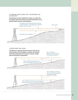
• FINDING AND USING THE “DIFFERENCE IN
ELEVATION”
Key elevations are often established in relation to a single refer-
ence called a bench mark. Once you know this dimension, you can
quickly compute the other critical elevations.
The distance from the bench mark to the top
of the foundation is the difference of elevation
between the two points.
Bench mark
Proposed top of foundation
• RESETTING THE LEVEL
The difference in elevation between the bench mark and any
critical elevation of the foundation is constant. The elevation
of the plane projected by the instrument, however, changes
when the instrument is repositioned.
The difference in elevation between the bench mark and any
critical elevation of the foundation is constant. The elevation
of the plane projected by the instrument, however, changes
when the instrument is repositioned.
DAY 1: Difference
between site line and top
of proposed foundation
DAY 1: Difference between top of
proposed foundation and bench mark
	 Building	foundAtions 15
DAY 2: Difference between top of proposed
foundation and bench mark remains the same.
DAY 2: Difference between
site line and top of proposed
foundation changes.
16 Building	the	structure 	
1 Stretch strings between the corner
stakes and mark the ground about
4 ft. outside of the strings. You
can use a 4-ft. level as a gauge to
measure the distance from the
string. To mark the line, use lime or
dry masonry mortar poured from a
paper cup or use brightly colored
spray paint.
STEP 2 Mark	and	dig	the	opening
Corner stake
Use a 4-ft. level to
gauge distance.
Flag
Offset stake
A dry mortar line or
spray paint marks the
area to dig.
2 Before you begin digging, establish the exact distance that you need to dig
below the bench mark. This requires that you know the design of the founda-
tion, including the exact heights of the materials that you’re going to use.
Make all measurements from the same reference: the targeted top-of-
foundation elevation. In this example, the top of foundation elevation has
been established at 24 in. above the bench mark.
The bench mark is 24 in.
below the planned top of the
foundation.
The top of the walls will be
96 in. above the top of the
footing.
4 in.
100 in. (96 in. + 4 in. above
the bottom of the excavation)
96 in.
76 in. (100 – 24 = 76)
below the bench mark
You know that the
bench mark is 24 in.
below the planned
top of the foundation;
therefore, the bottom
of the excavation
should be 76 in.
(100 – 24 = 76) below
the bench mark. 72 in.
frAMing	floors,	wAlls,	And	ceilings 17
2
3 Set up a leveling instrument outside of the opening. After leveling
the instrument, measure the height that it reads above the bench mark
(here, 14 in.). Add this amount to 76 in. The total, 90 in., is the distance from
the level line projected by the instrument to the bottom of the excavation.
14 in.
76 in.
90 in.
86 in.
Use a surveyor’s rod
to check the depth of
the opening.
Grade stake
Place a grade stake as a reference for the top of the footings. Drive this
down until the top is exactly 86 in. below the level line projected by the
leveling instrument. As the drawing on the facing page shows, this is 72 in.
below the bench mark and 96 in. below the desired top-of-foundation.
STEP 3 lay	out	the	fi
	rst	wall	
EXAMPLE 1 assumes that you removed the instrument at the end of the
excavation and have returned the next day to lay out the footings.
1 Pull a string from one offset
stake to the other along either
of the long walls.
2 Near each side of the excavation, drive in a pair of stakes,
with the string above roughly centered between them. Leave
about 8 in. of the stakes above the bottom of the excavation.
3 Set up the instrument in the bottom of the
opening and shoot the difference in elevation
between the line projected by the instrument
and the top of the grade stake.
4 Use the instrument and
a measuring stick or rod to
mark the four stakes at the
same distance below the
projected line.
Offset stake
Bench mark
Measuring stick
1
18 Building	the	structure 	
EXAMPLE 2 assumes that you did not set a grade stake
just after the excavation.
1 Set up the instrument
outside the opening and
shoot a level line anywhere
above the bench mark.
2 The difference in elevation between the bench mark
and the line projected by the instrument is 11 in.
3 The top of the footing has to be 72 in.
below the bench mark. Mark the stakes at
83 in. (72 + 11 = 83 ) below the line projected
by the instrument.
Offset
stake
Bench
mark
Measuring stick
83 in.
4 Once you have the four stakes marked,
attach a horizontal batter board between
each pair of stakes, with the tops of the
boards even with the marks.
Use screws rather than
nails to avoid jostling the
stakes out of position.
The batter board should be level,
exactly 72 in. below the bench
mark, and cross directly below the
string that represents the wall.
5 Transfer the exact location of the
string down to the batter boards.
You also could use a 6-ft.
spirit level or a plumb bob to
transfer this location.
String
attached to
bench mark
6 After marking both batter
boards, set a string from one
mark to the other. The string is
set at the desired elevation for
the top of the footing.
In plan view,
the string is
even with the
outside of the
foundation wall.
Location of
foundation wall
Set a self-leveling
laser with a
plumb beam on
the batter board
and slide it until
the beam strikes
the string.
frAMing	floors,	wAlls,	And	ceilings 19
2
1
1
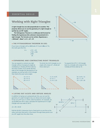
• THE PYTHAGOREAN THEOREM IN USE:
If you have a triangle with an Altitude of 12 and a Base of 16,
the math goes like this:
You can expand or contract any right
triangle without changing its angles by
multiplying or dividing all three sides by
the same number. If you divide all three
sides of the triangle just discussed by 4, for
example, you end up with a 3-4-5 triangle
that retains the exact same angles:
To shrink this 3-4-5 triangle to a tri-
angle with a base of 1, divide all
three sides by 4:
To expand this 0.75-1-1.25 triangle
back to a triangle with a base of 16,
multiply all three sides by 16:
A
B
H
• EXPANDING AND CONTRACTING RIGHT TRIANGLES
12 ÷ 4 = 3
16 ÷ 4 = 4
20 ÷ 4 = 5
3 ÷ 4 = 0.75
4 ÷ 4 = 1
5 ÷ 4 = 1.25
16 × 0.75 = 12
16 × 1 = 16
16 × 1.25 = 20
• LAYING OUT ACUTE AND OBTUSE ANGLES
In addition to laying out a perpendicular line, you can use the
geometry of a right triangle to lay out obtuse and acute angles.
To lay out a 45º turn in a 30-ft.-wide foundation, for example, set
up parallel lines 30 ft. apart. Calculate the hypotenuse of a right
triangle with two sides of 30 ft.:
√2 × 30 = 42.42
Pull the 42.42-ft. dimension from a fixed point on one line to the
other and mark that point. A line drawn through these points runs
at a 45° angle from the other lines.
30 ft.
42.42 ft.
Working with Right Triangles
A right triangle has one side perpendicular to another. This
property allows you to use the geometry of a right triangle to
quickly lay out 90º angles.
The Pythagorean Theorem is a 2,500-year-old formula for
finding the hypotenuse (the unknown measurement) of a
right triangle. The formula can be written: Hypotenuse =
√ Altitude² + Base² or H = √A2
+ B2
.
e s s e n t i A l 	 s k i l l s
	 Building	foundAtions 19
H = √122
+ 162
√144 + 256
√400
20
20 Building	the	structure
STEP 5 lay	out	the	corners	of	the	foundation
1 Measure 30 ft. from the
first string set up in step 3,
and drive a pair of stakes
at each end to straddle the
30-ft. measurement.
STEP 4 lay	out	the	other	long	wall
2 Use the leveling instrument to
mark the stakes at the same eleva-
tion as the first two pairs of stakes
(i.e., 72 in. below the bench mark).
4 Adjust the posi-
tion of the string
along the batter
boards until it’s
exactly 30 ft. away
from and parallel
to the first string.
3 Attach batter boards
with the top edge even
with the marks.
First string set up
Plan view of excavation
1 Mark the offset stake string at
10 ft. to establish the first corner mark.
2 Plumb down to the lower string
and mark the location on the
foundation wall string below.
3 Measure and mark the
length of the foundation
wall (38 ft.) along the
lower string.
5 Pull a tape from the 38-ft. mark
diagonally until the tape reads
48 ft. 5 in.
6 Repeat step 4 to
locate the last corner.
7 The distance between the two marks
on the second string should be 38 ft.
Offset stake
4 Use the Pythagorean
Theorem, as described
on p. 19, to determine
the hypotenuse of a
right triangle with sides
of 38 ft. and 30 ft. This
comes to 48 ft. 5 in.
1
STEP 6 form	the	footing
1 Mark the batter boards 4 in. outside of the strings
that represent the outside of the foundation wall.
2 Attach lines that run from
one mark to the other.
3 Place 2x4 forms 1⁄8 in. away from the
string. Place stakes outside of the form.
The top of the form should be even with
the string.
4 To mark locations for the side
walls on the forms, set strings
that extend across the opening
from one of the form boards
to the other so the strings cross
over the corner marks you made
on the long wall strings.
5 Measure 4 in. from the sidewall strings and
mark the location of the outside of the footings
for the two side walls, then run strings between
the marks.
6 Place forms
along the
strings.
7 On the forms, measure and mark 12 in. in from the
strings representing the outside walls of the foundation.
These measurements mark the inside of the footings.
8 Build a form
along the inside
of these lines
to complete the
perimeter foot-
ing forms.
On many houses, the
plans specify footings for
piers (or posts). If these
are specified, carefully
measure from the strings
that represent the walls
to lay out the exact posi-
tions of the pier footings.
Form the pier footings
with 2x4s at the same
height as the perimeter
footings.
Make sure that the positions of the strings that represent
the foundation walls are clearly marked on the forms.
	 Building	foundAtions 21
22 Building	the	structure 	
STEP 8 Prepare	for	the	footing	pour
Install steel as required by your local code and by the
specifications on your plan. Check with the plumber
and septic system subcontractor for possible pipe place-
ment and any pipes or sleeves in the form. If a sump
pump is needed, place the pipe through the form.
In most jurisdictions, you’re required to have the
footing examined by the building inspector at this
point. Once you get the go-ahead from the inspector,
calculate the volume of concrete needed and schedule
a delivery. (There will be information on estimating
concrete quantities in the next section.)
STEP 7 dig	the	footings
Remove the strings and dig the footing between the
forms with a square shovel. Make the bottom of the
footing 8 in. from the top of the form. The bottom of the
trench should be flat and consist of undisturbed soil, and
the sides should extend straight down from the forms.
Measure frequently to
avoid overdigging.
Place vertical pieces
of steel precisely
by measuring and
marking directly on
the forms.
To measure the depth, place a
straightedge across the form and
measure to its bottom edge.
STEP 9 Pour	the	footing
Pour the concrete and strike it even with the top of the
form. Form a keyway in the footing, if your foundation
plan calls for one.
Place strips of wood in the wet
concrete just after you’ve placed
the concrete to mold the keyways.
Pour the concrete and strike it even with the top of the
form. Form a keyway in the footing, if your foundation
Place strips of wood in the wet
concrete just after you’ve placed
the concrete to mold the keyways.
frAMing	floors,	wAlls,	And	ceilings 23
1
STEP 10 lay	out	the	walls
A few days after pouring the footings, you can lay out the
foundation walls on the hardened concrete. The top of
the concrete should be level and at the correct elevation.
The locations of the walls are recorded on the forms.
Once you’ve determined that the layout is precisely
correct, you can build 96-in.-tall walls from poured con-
crete, concrete block, or insulated concrete forms. Any of
these wall systems would bring the foundation up to the
targeted elevation.
In cold climates, part of the footing may have to be dug
deeper than 8 in. If you’re planning a walk-out basement
door, the footing under and near the door may have to be
stepped down to get it below the frost line. Check with
your building inspector to see what you need.
1 Pull strings from the marks on
the forms to check the layout.
2 Check the
lengths of the
four walls.
4 Strike chalklines on the concrete.
3 Check the diagonals in
both directions to make
sure the layout is correct.
Marks on forms
24 Building	the	structure 	
Setting Up a Line Quickly and Accurately
Because builders use stringlines extensively for concrete, masonry, and carpentry
layout, it’s important to learn how to set one up quickly and accurately. Lines
generally need to be drawn tightly to remove sag, so it’s usually necessary
to attach them securely.
• ANCHORING THE LINE TO WOOD
SURFACES
When you have a wood surface, it’s often possible to drive a
nail halfway into the surface, then tie the line off to the nail.
1 Loop the string
around your index
finger, and twirl your
finger several times.
2 Hook the loop over
the nail.
3 Pull the loose end of
the string one way and
the taut end the other.
1 Loop the
string around
your thumb and
forefinger.
Method One
Method Two
2 Turn your
hand down
to create two
loops.
3 Slip the loops
over the nail
and pull the
string tight.
e s s e n t i A l 	 s k i l l s
3 Slip the loops
over the nail
and pull the
string tight.
24 Building	the	structure
frAMing	floors,	wAlls,	And	ceilings 25
1
• LINE BLOCKS
Line blocks allow you to secure a line without
using nails. This has a few advantages: You can
attach the string to finished surfaces without
making a nail hole; you can secure the string to
concrete and masonry surfaces; and you can adjust
the position of the line easily.
2 Wind the string
back around the
middle of the block.
3 Pull the string back through
the kerf.
4 Hook the line
block on any
square edge.
Tension from
the line holds it
in place.
• LAYING OUT ONE LINE
PARALLEL TO ANOTHER
1 Attach the
first string at the
desired location.
2 Measure the desired
distance to other batter
boards and mark a rough
measurement.
To lay out one line parallel to and a
set distance away from another, use a
pair of batter boards for each line.
3 Attach the
second string
to batter
boards near the
preliminary mark.
4 Swing the tape in an arc, and adjust the
line until it’s at the high point of the arc.
1 Pull the string through
the kerf cut in the back of
the block.
	 Building	foundAtions 25
26 Building	the	structure 	
laying	out	a	crawlspace	foundation
In	this	example,	the	foundation	is	a	24-ft.	by	40-ft.	crawlspace	that	projects	
about	32	in.	above	the	high	point	in	the	grade	around	the	house.	The	foun-
dation	will	be	built	from	8	x	8	x	16-in.	concrete	blocks.	(These	are	often	
specifi
	ed	as	CMUs,	or	concrete	masonry	units.)
The	house	is	being	built	in	an	area	where	the	frost	line	is	24	in.	The	
excavator	has	scraped	the	ground	clear	of	organic	matter	but	left	the	grade	
roughly	the	same	as	the	surrounding	terrain.	The	opening	is	several	feet	
larger	than	the	footprint	of	the	house.	The	location	of	the	house	has	been	
roughly	staked	out	by	the	owner	and	architect.	
1 Set up the leveling instrument
and shoot the elevation of the four
corners staked out by the owner.
About 10 ft. beyond the high corner
and along the line the long wall will
follow, drive in two large stakes.
STEP 1 find	the	high	corner	and	establish	the	elevation	of	the	foundation
2 Check the difference in elevation
between the level line projected
by the instrument and the grade at
the high corner. In this example, the
level line shot by the instrument is
47 in. higher than the grade at the
high corner. Since the planned top of
foundation elevation is 32 in. above
grade at this corner, the top of the
foundation should be laid out 15 in.
below the level line projected by the
instrument (47 – 32 = 15). Repeat for
the other corners.
The stakes need to be about 5 ft. long,
and they should be made out of sub-
stantial pieces of lumber (2x4s or 2x6s).
Place stakes 4 ft. apart so they
straddle the line of the long
wall of the house.
Hold a ruler vertically with the
15-in. dimension even with the
line shot by the instrument.
Use a screw gun to
attach a batter board
to the stakes at this
elevation.
Mark the stake
at the bottom
of the ruler.
Corner stake
47 in.
Level line
Level sight line
Proposed foundation
along grade
High corner
High corner
stake
15 in.
32 in.
frAMing	floors,	wAlls,	And	ceilings 27
2
STEP 2 create	a	level	plane	for	the	layout
Because the batter boards are at the same elevation, any lines extended from
one batter board to another will be level and in the same plane. This level
plane does two things. It establishes the elevation of the top of the foundation,
and it ensures that measurements made along lines in that plane are accurate.
The top of the first batter board is set at the
elevation for the top of the foundation, 15 in.
below the level line shot by the instrument.
Set more batter boards
in line with the two
long walls 15 in. below
the level line.
Don’t install batter boards
for the side walls until after
the excavator finishes.
Level plane
STEP 3 lay	out	a	24-ft.	by	40-ft.	rectangle	in	the	level	plane
3 Plumb up from the corner stake, and
use a felt-tipped pen to mark the string.
1 Set a string on the batter boards directly above the corner
stakes. This string marks the outside edge of one of the walls.
Corner stake
2 Set a second
string on the other
pair of batter
boards; carefully
adjust this string
until it’s parallel to
and exactly 24 ft.
away from the first
string. This string
represents the
outside edge of the
other long wall.
4 Use geometry to cal-
culate the hypotenuse
of a right triangle with
an Altitude of 24 and
a Base of 40. Plugging
the numbers into the
Pythagorean Theorem,
the math is:
H = √24² + 40²
H = √576 + 1,600
H = √2,176
H = 46.648
5 Use a tape laid out in the engineer’s scale to pull 46.648
diagonally across from the two marks on the first string, and
mark the third and fourth corners on the second string.
Corner stake
A = 24
B = 40
H = 46.648
1
Plumb up from the corner stake, and
use a felt-tipped pen to mark the string.
4 Use geometry to cal-
Use geometry to cal-
culate the hypotenuse
STEP 4 record	the	layout	on	the	batter	boards
According to the plan, the foundation walls are 8 in. wide and the footings
are 16 in. wide. The footings must be centered under the walls. Around the
outside of the footing, you need an additional 6 in. or 8 in. for a drain system.
To accommodate the footing and the drain system, a 24-in.-wide footing
trench is planned.
8-in. foundation walls
16-in. footings
centered under
walls
Lay out both sides of the
foundation walls, both sides
of the footings, and the extra
8 in. for the drain system on
the batter boards.
Trench
8-in. foundation walls
16-in. footings centered
under walls
Allow 6 in.
or 8 in. for a
drain.
Trench
Measure the distance from the face of each batter
board to the corner mark on the string, and record
this measurement on the face of the batter board.
STEP 5 Mark	the	ground	for	the	footing	dig
1 To mark the trench for the long
walls, set up lines on the two outside
marks on the batter boards. Transfer
these locations to the ground with a
level, a plumb bob, or a laser.
2 To mark the trench for the side
walls, transfer the locations of the
four corners from the string to the
ground. Measure out 12 in. in both
directions.
3 Set strings just above the ground at
these locations, and mark the ground
with lime, mortar, or spray paint.
Transfer loca-
tions to the
ground.
Measure 12 in. in
both directions. Mark the
ground along
the strings.
28 Building	the	structure
STEP 6 dig	the	footing	to	the	right	depth
1 The bottom of the footing has to be at least 24 in. deep
to get it below the frost line. Also, because the specified
footing is 8 in. thick and the block courses will each be
8 in. high, the distance between the top of the founda-
tion and the bottom of the footing has to be evenly
divisible by 8 in.
2 In this example, you have scheduled a backhoe to dig
the footing the day after the layout, which means you’ve
had to move the leveling instrument. For the excavation
of the footing, you set it up again; this time it projects a
level line that’s 93⁄4 in. above the top of foundation.
The footing
needs to be
at least 24 in.
below the
frost line.
70 in. below the top
of the foundation
line is not divisible
by 8 in.
Measure from the strings on the
batter boards to find the lowest
corner—in this example, 46 in.—
below the top of the foundation.
Increasing the trench depth to
72 in. places the footing below
the frost line and conforms to
the 8-in. modular scheme.
The depth of the footing will be
813⁄4 in. (72 + 93⁄4) below the line shot
by the instrument.
The new level line is 93⁄4 in.
above the proposed
foundation top.
3 Remove the strings on the batter board to make room
for the backhoe. To get the trench in the right place, the
excavator digs to the lines you’ve made on the ground.
Check the depth using the
leveling instrument and a rod
marked at 813⁄4 in.
When the trench gets a little more than
32 in. below the surface, you can step the
depth up 8 in. From this point, make the
bottom 733⁄
3⁄
3 4
⁄4
⁄ in. (813⁄
3⁄
3 4
⁄4
⁄ – 8 = 733⁄
3⁄
3 4
⁄4
⁄ ) from the
line shot by the instrument.
1
	 Building	foundAtions 29
1
30 Building	the	structure
STEP 7 finish	the	trench	by	hand
STEP 8 get	ready	for	the	pour
7 Lay out and dig
footings for piers. They
don’t have to be below
the frost line but should
conform to the 8-in.
modular scheme men-
tioned on p. 29.
1 After the excavator finishes, install
batter boards for the footing side walls.
Attach new strings on the long wall
batter boards. Measure the distance
recorded on the face of the batter
board to mark one of the corners. 2 Measure 40 ft. down the string,
and mark the second corner.
3 Pull the 46.648-ft.
diagonals to lay out
the third and fourth
corners.
4 Pull strings
through the corner
marks to the side
batter boards, and
mark the batter
boards where the
strings cross them.
Mark the foundation wall.
5 Set strings on the
inside-of-trench and
outside-of-trench
marks on the batter
boards. Level down
from the strings to
see how well the
trench conforms
to the layout. Use
shovels to straighten
out the sides of the
trench and remove
any loose dirt from
the bottom.
Mark both sides
of the trench.
6 Measure the elevation of the bottom of the
footing against the strings. It should be 72 in.
in the lower area and 64 in. in the upper area.
Where the distance is less than these, dig to the
target distances. Be careful not to dig too deep.
1 Set lines on the marks for the
outside of the footing on the
batter boards.
3 Use 2x8s to form
the outside of the
footings.
2 Transfer these
locations to the
bottom of the trench
to get the forms in
the right place.
4 As you install the forms, measure up to the lines
to make sure you get the forms at the right eleva-
tion. The tops of the forms have to be at a height
that conforms to the 8-in. modular scheme. The
footings for the piers don’t require forms.
Set the rebar for the
footings as required by
your local code and the
specs on the plans.
1
STEP 10 lay	out	the	walls
After the concrete hardens, set lines on the batter boards and use a level,
plumb bob, or laser to transfer the locations of the walls to the top of the foot-
ing. Snap chalklines on the concrete to lay out the walls. Techniques for laying
the blocks up to the line will be discussed in the final section of this chapter.
Before beginning the block work, make a quick checklist of the things to
either allow for or include in the walls:
• Drainpipe to allow moisture inside the crawlspace to go through the wall
and into the perimeter drain system
• Access door
• Opening for an HVAC duct
• Foundation vents
• Beam pockets
• Anchors to bolt the frame to the foundation
STEP 9 Pour	the	footing
Before the concrete truck arrives, set up the leveling instrument and measure
the difference in elevation between the top of the batter boards and the line
shot by the instrument. Add the amount—in 8-in. increments—that you need
to go down to get the tops of the pier footings at the right height.
Measure down from
the level line projected
by the instrument to
pour the piers to the
correct elevation.
Inside the footing
trench, pour the
concrete even with
the top of the forms.
72 in.
64 in.
48 in. Line shot by
leveling instrument
Cave-ins:
A Deadly Hazard
The sides of trenches and
basement excavations can
collapse without warning. If a
person is buried over his head
in such a collapse, the chances
of survival are less than one in
ten. There are four things you
can do to reduce the chance of
a deadly cave-in:
• Any time you excavate
an opening for a basement,
make sure you dig at least
4 ft. beyond the footprint of
the house; this keeps workers
away from the deadly perim-
eter of the excavation.
• Slope the sides of the
excavation away from the
opening.
• Pile the spoils from a trench
excavation at least 2 ft. back
from the edge.
• Use a shoring system for
deep trenches. For more on
trenching safety, go to this
OSHA site: http://www.osha.
gov/SLTC/trenchingexcavation/
construction.html
sAfety	first
	 Building	foundAtions 31
32 Building	the	structure
Building	outside	the	Box	
Although	a	rectangular	fl
	oor	plan	has	the	advantages	of	speed	and	
economy,	designers	and	homeowners	often	desire	more	complicated	
shapes.	The	most	common	method	of	breaking	out	from	the	four	
walls	of	a	rectangular	house	is	to	add	more	rectangles	in	the	form	
of	ells,	wings,	and	insets.	There	are	many	occasions,	however,	when	
designers	abandon	the	rectangle	altogether	and	draw	up	buildings	or	
parts	of	buildings	with	obtuse	or	acute	angles	or	curved	walls.
To	lay	out	these	different	shapes,	follow	the	same	basic	sequence	
that	has	just	been	described.	First,	lay	out	a	level	plane	at	either	the	
top-of-foundation	or	the	top-of-footing	elevation.	Then	lay	out	the	
shape	within	that	plane.
Adding	rectangles	to	rectangles
To lay out these foundations, start by laying out the main rectangle and then
add more batter boards or forms to lay out the additional rectangles. Use
geometry to get the walls of the secondary rectangles square to the primary
rectangle.
Main rectangle
Added
rectangle
Parallel lines
Parallel lines Parallel lines
Added
rectangle
Added
rectangle
Equal diagonals
Batter board
1
Moving	away	from	the	right	angle
Once in a while, designers draw up buildings with walls that are not square to
one another. To lay out these acute (less than 90º) or obtuse (more than 90°)
angles, you can either use a precise surveying instrument or geometry. The
designer should specify the point from which to pull the measurement as well
as the exact dimensions of both the parallel line and the diagonal measure-
ment. If the angle is simply specified in degrees, however, it’s up to you to
calculate the dimensions of a right triangle that corresponds to the degrees
specified. To make these calculations, use the techniques described in
“Working with Right Triangles” on p. 19.
2 From a specified point,
pull a specified dimension
diagonally across the layout
and mark the parallel line
with a felt-tipped pen.
2 After loosening the
clamp on the horizontal
scale, point it so that it
is shooting parallel to
the line.
3 Set the horizontal scale to
the zero mark. Turn the instru-
ment to the desire angle.
• SURVEYING INSTRUMENT • GEOMETRY
3 Set up batter
boards and
string that runs
directly across
the marks. This
string represents
the outside of
the angled wall.
1 Build batter boards at the
correct elevation, and affix a
line a set distance from and
parallel to one of the walls on
the main rectangle.
1 Set the instrument
directly over a point on a
base line of your layout.
4 Transfer the line shot by the
instrument down to the batter
board and mark that point.
laying	out	curved	foundations
Curved foundations are usually drawn as circles or seg-
ments of circles. The first step in laying out a circular,
semicircular, or arced foundation is to establish a pivot
point. The location of this point should be specified in the
plans. Lay out this point at the desired elevation, using a
stake or a batter board. Once you’ve established the pivot
point, create a beam compass to serve as the radii needed
to lay out the parts of the foundation. On the beam com-
pass, measure and mark the parts of the foundation out
from the pivot point. These measurements include the dis-
tances from the pivot point to: the inside and outside of
the footing trench; the inside and outside of the concrete
footing; the inside and outside of the foundation wall;
and the center of the foundation wall.
After setting up a form or
batter board to hold the beam
level, swing the compass.
You can make the
beam compass on
site, using a strip of
wood and a nail for
the pivot.
Mark the beam
compass with
foundation
dimensions.
Batter boards
are at the same
elevation.
	 Building	foundAtions 33
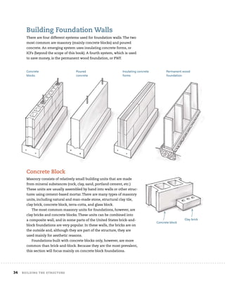
Building	foundation	walls
There	are	four	different	systems	used	for	foundation	walls.	The	two	
most	common	are	masonry	(mainly	concrete	blocks)	and	poured	
concrete.	An	emerging	system	uses	insulating	concrete	forms,	or	
ICFs	(beyond	the	scope	of	this	book).	A	fourth	system,	which	is	used	
to	save	money,	is	the	permanent	wood	foundation,	or	PWF.	
concrete	Block	
Masonry	consists	of	relatively	small	building	units	that	are	made	
from	mineral	substances	(rock,	clay,	sand,	portland	cement,	etc.)	
These	units	are	usually	assembled	by	hand	into	walls	or	other	struc-
tures	using	cement-based	mortar.	There	are	many	types	of	masonry	
units,	including	natural	and	man-made	stone,	structural	clay	tile,	
clay	brick,	concrete	block,	terra-cotta,	and	glass	block.
The	most	common	masonry	units	for	foundations,	however,	are	
clay	bricks	and	concrete	blocks.	These	units	can	be	combined	into	
a	composite	wall,	and	in	some	parts	of	the	United	States	brick-and-
block	foundations	are	very	popular.	In	these	walls,	the	bricks	are	on	
the	outside	and,	although	they	are	part	of	the	structure,	they	are	
used	mainly	for	aesthetic	reasons.
Foundations	built	with	concrete	blocks	only,	however,	are	more	
common	than	brick-and-block.	Because	they	are	the	most	prevalent,	
this	section	will	focus	mainly	on	concrete	block	foundations.
Concrete
blocks
Poured
concrete
Permanent wood
foundation
Concrete block
Clay brick
Insulating concrete
forms
34 Building	the	structure
blocks concrete foundation
forms
Masonry	consists	of	relatively	small	building	units	that	are	made	
from	mineral	substances	(rock,	clay,	sand,	portland	cement,	etc.)	
These	units	are	usually	assembled	by	hand	into	walls	or	other	struc-
tures	using	cement-based	mortar.	There	are	many	types	of	masonry	
units,	including	natural	and	man-made	stone,	structural	clay	tile,	
The	most	common	masonry	units	for	foundations,	however,	are	
clay	bricks	and	concrete	blocks.	These	units	can	be	combined	into	
a	composite	wall,	and	in	some	parts	of	the	United	States	brick-and-
block	foundations	are	very	popular.	In	these	walls,	the	bricks	are	on	
Concrete block
Clay brick
Building	foundation	walls
There	are	four	different	systems	used	for	foundation	walls.	The	two	
most	common	are	masonry	(mainly	concrete	blocks)	and	poured	
concrete.	An	emerging	system	uses	insulating	concrete	forms,	or	
ICFs	(beyond	the	scope	of	this	book).	A	fourth	system,	which	is	used	
to	save	money,	is	the	permanent	wood	foundation,	or	PWF.	
concrete	Block	
Masonry	consists	of	relatively	small	building	units	that	are	made	
from	mineral	substances	(rock,	clay,	sand,	portland	cement,	etc.)	
These	units	are	usually	assembled	by	hand	into	walls	or	other	struc-
tures	using	cement-based	mortar.	There	are	many	types	of	masonry	
units,	including	natural	and	man-made	stone,	structural	clay	tile,	
clay	brick,	concrete	block,	terra-cotta,	and	glass	block.
The	most	common	masonry	units	for	foundations,	however,	are	
clay	bricks	and	concrete	blocks.	These	units	can	be	combined	into	
a	composite	wall,	and	in	some	parts	of	the	United	States	brick-and-
block	foundations	are	very	popular.	In	these	walls,	the	bricks	are	on	
the	outside	and,	although	they	are	part	of	the	structure,	they	are	
used	mainly	for	aesthetic	reasons.
Foundations	built	with	concrete	blocks	only,	however,	are	more	
common	than	brick-and-block.	Because	they	are	the	most	prevalent,	
this	section	will	focus	mainly	on	concrete	block	foundations.
Concrete
blocks
Poured
concrete
Permanent wood
foundation
Concrete block
Clay brick
Insulating concrete
forms
2
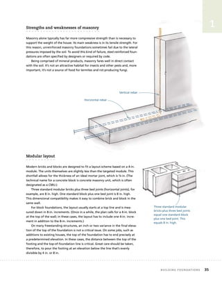
strengths	and	weaknesses	of	masonry
Masonry alone typically has far more compressive strength than is necessary to
support the weight of the house. Its main weakness is in its tensile strength. For
this reason, unreinforced masonry foundations sometimes fail due to the lateral
pressures imposed by the soil. To avoid this kind of failure, steel-reinforced foun-
dations are often specified by designers or required by code.
Being comprised of mineral products, masonry fares well in direct contact
with the soil. It’s not an attractive habitat for insects and other pests and, more
important, it’s not a source of food for termites and rot-producing fungi.
Modular	layout
Modern bricks and blocks are designed to fit a layout scheme based on a 4-in.
module. The units themselves are slightly less than the targeted module. This
shortfall allows for the thickness of an ideal mortar joint, which is 3⁄8 in. (The
technical name for a concrete block is concrete masonry unit, which is often
designated as a CMU.)
Three standard modular bricks plus three bed joints (horizontal joints), for
example, are 8 in. high. One standard block plus one bed joint is 8 in. high.
This dimensional compatibility makes it easy to combine brick and block in the
same wall.
For block foundations, the layout usually starts at a top line and is mea-
sured down in 8-in. increments. (Once in a while, the plan calls for a 4-in. block
at the top of the wall; in these cases, the layout has to include one 4-in. incre-
ment in addition to the 8-in. increments.)
On many freestanding structures, an inch or two variance in the final eleva-
tion of the top of the foundation is not a critical issue. On some jobs, such as
additions to existing houses, the top of the foundation has to end precisely at
a predetermined elevation. In these cases, the distance between the top of the
footing and the top-of-foundation line is critical. Great care should be taken,
therefore, to pour the footing at an elevation below the line that’s evenly
divisible by 4 in. or 8 in.
Horizontal rebar
Vertical rebar
Three standard modular
bricks plus three bed joints
equal one standard block
plus one bed joint. This
equals 8 in. high.
	 Building	foundAtions 35
strengths	and	weaknesses	of	masonry
Masonry alone typically has far more compressive strength than is necessary to
support the weight of the house. Its main weakness is in its tensile strength. For
this reason, unreinforced masonry foundations sometimes fail due to the lateral
pressures imposed by the soil. To avoid this kind of failure, steel-reinforced foun-
dations are often specified by designers or required by code.
Being comprised of mineral products, masonry fares well in direct contact
with the soil. It’s not an attractive habitat for insects and other pests and, more
important, it’s not a source of food for termites and rot-producing fungi.
Modular	layout
Modern bricks and blocks are designed to fit a layout scheme based on a 4-in.
module. The units themselves are slightly less than the targeted module. This
shortfall allows for the thickness of an ideal mortar joint, which is 3⁄8 in. (The
technical name for a concrete block is concrete masonry unit, which is often
designated as a CMU.)
Three standard modular bricks plus three bed joints (horizontal joints), for
example, are 8 in. high. One standard block plus one bed joint is 8 in. high.
This dimensional compatibility makes it easy to combine brick and block in the
same wall.
For block foundations, the layout usually starts at a top line and is mea-
sured down in 8-in. increments. (Once in a while, the plan calls for a 4-in. block
at the top of the wall; in these cases, the layout has to include one 4-in. incre-
ment in addition to the 8-in. increments.)
On many freestanding structures, an inch or two variance in the final eleva-
tion of the top of the foundation is not a critical issue. On some jobs, such as
additions to existing houses, the top of the foundation has to end precisely at
a predetermined elevation. In these cases, the distance between the top of the
footing and the top-of-foundation line is critical. Great care should be taken,
therefore, to pour the footing at an elevation below the line that’s evenly
divisible by 4 in. or 8 in.
Horizontal rebar
Vertical rebar
Three standard modular
bricks plus three bed joints
equal one standard block
plus one bed joint. This
equals 8 in. high.
1
strengths	and	weaknesses	of	masonry
Masonry alone typically has far more compressive strength than is necessary to
support the weight of the house. Its main weakness is in its tensile strength. For
this reason, unreinforced masonry foundations sometimes fail due to the lateral
pressures imposed by the soil. To avoid this kind of failure, steel-reinforced foun-
dations are often specified by designers or required by code.
Being comprised of mineral products, masonry fares well in direct contact
with the soil. It’s not an attractive habitat for insects and other pests and, more
important, it’s not a source of food for termites and rot-producing fungi.
Horizontal rebar
Horizontal rebar
Horizontal rebar
Vertical rebar
Vertical rebar
Vertical rebar
36 Building	the	structure
unit	spacing	along	the	length	of	the	wall	
The lengths of masonry units also fit into a 4-in. modular scheme. One brick
with one head joint (vertical joint) is 8 in. long. One block with one head joint
is 16 in. long. Similarly, the dimensions of the widths of these units also fit the
modular scheme. A brick with a joint is 4 in. wide; a block with a joint is 8 in.
wide. This ensures that the joints of each course are offset by half the length of
the unit from the course below when you build corners.
When you build corners for any masonry wall, it’s important to make sure
you maintain the correct bonding pattern. After you build the first corner of a
foundation, for example, you have to measure or set the units in place dry to
determine which direction to place the first unit in the second corner.
fudging	the	layout
Although the 4-in. and 8-in. module
is the rule in masonry, there is a little
wiggle room. The courses can be
expanded or contracted slightly by
adjusting the thickness of the mortar
joints. Most building codes, how-
ever, limit the amount that mortar
joints can vary. The International
Residential Code, for example, speci-
fies that bed joints for a masonry
foundation must be between 3⁄8 in.
and 1⁄2 in. thick. The one exception to
this rule is that the bed joint on the
footing can be up to 3⁄4 in. thick. This
means that as much as 13⁄8 in. can be
gained in a foundation that’s nine
block courses high (1⁄8 in. × 8 =
1 + 3⁄8 in. = 13⁄8 in.).
One brick with one head
joint is 8 in. long.
One block with one
head joint is 16 in. long.
Dividing space (136 in.) by 16 in. (block plus
head joint) equals 81⁄2 blocks.
In this example, the end block will need
to be turned in line with the other wall.
72 in. (nine courses with
3⁄8-in. bed joints)
733⁄8 in. (first-course bed joint
of 3⁄4 in. plus nine courses
with 1⁄2-in. bed joints)
1
wAy s 	 o f 	w o r k i n g
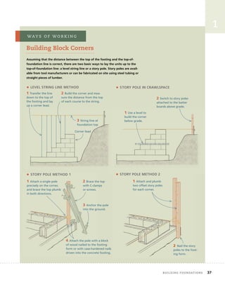
Building Block Corners
Assuming that the distance between the top of the footing and the top-of-
foundation line is correct, there are two basic ways to lay the units up to the
top-of-foundation line: a level string line or a story pole. Story poles are avail-
able from tool manufacturers or can be fabricated on site using steel tubing or
straight pieces of lumber.
• LEVEL STRING LINE METHOD
2 Build the corner and mea-
sure the distance from the top
of each course to the string.
1 Transfer the line
down to the top of
the footing and lay
up a corner lead.
3 String line at
foundation top
Corner lead
• STORY POLE METHOD 1
3 Anchor the pole
into the ground.
4 Attach the pole with a block
of wood nailed to the footing
form or with case-hardened nails
driven into the concrete footing.
1 Attach a single pole
precisely on the corner,
and brace the top plumb
in both directions.
2 Brace the top
with C-clamps
or screws.
• STORY POLE METHOD 2
2 Nail the story
poles to the foot-
ing form.
1 Attach and plumb
two offset story poles
for each corner.
• STORY POLE IN CRAWLSPACE
2 Switch to story poles
attached to the batter
boards above grade.
1 Use a level to
build the corner
below grade.
	 Building	foundAtions 37
38 Building	the	structure
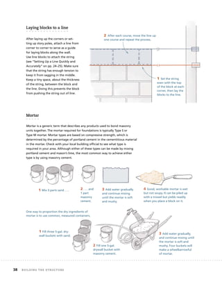
laying	blocks	to	a	line
After laying up the corners or set-
ting up story poles, attach a line from
corner to corner to serve as a guide
for laying blocks along the wall.
Use line blocks to attach the string
(see “Setting Up a Line Quickly and
Accurately” on pp. 24–25). Make sure
that the string has enough tension to
keep it from sagging in the middle.
Keep a tiny space, about the thickness
of the string, between the block and
the line. Doing this prevents the block
from pushing the string out of line.
Mortar
Mortar is a generic term that describes any products used to bond masonry
units together. The mortar required for foundations is typically Type S or
Type M mortar. Mortar types are based on compressive strength, which is
determined by the percentage of portland cement in the cementitious material
in the mortar. Check with your local building official to see what type is
required in your area. Although either of these types can be made by mixing
portland cement and mason’s lime, the most common way to achieve either
type is by using masonry cement.
1 Set the string
even with the top
of the block at each
corner, then lay the
blocks to the line.
2 After each course, move the line up
one course and repeat the process.
4 Good, workable mortar is wet
but not soupy. It can be piled up
with a trowel but yields readily
when you place a block on it.
1 Mix 3 parts sand . . . 2 . . . and
1 part
masonry
cement.
3 Add water gradually
and continue mixing
until the mortar is soft
and mushy.
One way to proportion the dry ingredients of
mortar is to use common, measured containers.
1 Fill three 5-gal. dry-
wall buckets with sand.
2 Fill one 5-gal.
drywall bucket with
masonry cement.
3 Add water gradually,
and continue mixing until
the mortar is soft and
mushy. Four buckets will
make a wheelbarrowful
of mortar.
1
troweling	techniques
Wielding a trowel is a physical skill that can be acquired only through
practice. Although there is no substitute for picking up a trowel and
having at it, here are a few basic techniques to get you started.
1 Pile mortar into a mound
in a mortar pan.
2 Scoop a full
but manageable
trowelful.
3 With the fully loaded
trowel a few inches above
the footing, give the
trowel a slight downward
tilt. Without stopping,
rotate your wrist and pull
the trowel.
4 The motion is like
the pull stroke when
you’re working with a
handsaw.
• TROWELING THE FIRST COURSE
• TROWELING BLOCKS
To butter the end of a block (or brick), you have to turn the
trowel over. The challenge is to keep the mortar from slid-
ing off the overturned trowel.
1 Pick up half a
trowelful.
2 With the mortar
facing up, thrust the
trowel straight down
and stop it abruptly.
3 With the mortar
flattened against the
trowel, it stays put as
you butter the ends
of the block.
Maximize the Bond
In addition to having com-
pressive strength, mortar has
to bond the masonry units
together tenaciously. To maxi-
mize bond, the units should
be dry and the mortar should
be as wet as possible and still
have enough body to sup-
port the weight of the units.
When mortar is spread on the
surface of a dry, porous unit,
the mortar is sucked into the
pores, creating a mechanical
as well as chemical bond.
There is an enduring myth
that masons should soak
units before laying them in
a wall. In most cases, this is
false. Most clay bricks and
all concrete blocks should be
kept dry before laying them
in a wall. On rare occasions,
unusually porous and dry clay
bricks have an excessively
high initial rate of absorption
(IRA). These bricks suck the
moisture out of the mortar at
such a rate that the mortar
dries almost immediately. This
makes them difficult to work
with and can have a nega-
tive effect on the bond. In
these cases, the bricks should
be wetted, then allowed to
surface-dry before they’re set
in the wall. Wet masonry units
should never be laid in a wall.
toP	tiP
	 Building	foundAtions 39
rebar	set	in	footing
Block walls are often reinforced with steel and grout. The
design should be drawn up by an engineer, or follow the
specifications of the building code in your area. Rebar
should be laid out so that it emerges from the footing
in the center of the block cores. After the footing pour,
builders sometimes bend incorrectly placed rebar to get it
in line with the block core. This practice compromises the
structural integrity of the system and should be avoided.
It’s far better to lay out the pieces of steel correctly prior
to the footing pour.
create	a	cleanout
It is important to keep the footing around the verti-
cal rebar clear of mortar droppings so the cavity can be
completely filled with grout later. To ensure that the
footing around the vertical rebar remains clean as you lay
up the wall, you need to cut a “cleanout,” a 4-in. by 4-in.
opening in the first block that goes over the rebar. As
the blocks are laid up, you can reach in and clean out the
droppings around the rebar several times a day.
As the blocks are laid up, keep the rebar in the center
of the core. Wire rebar positioners are available for
this purpose.
grout	block	cavities
The grout must bond the masonry units and the rebar
together. To achieve this bond, grout is much richer in
portland cement than concrete and it has much more
water. Because grout must fill the block cavities com-
pletely, pea gravel is often specified as the coarse aggre-
gate. Structural engineers often specify the proportions
for the grout on commercial masonry jobs. For residential
projects, however, you can usually get an acceptable mix
by conferring with your concrete supplier.
Rebar tied to
horizontal rebar
set in footing
prior to pour
Rebar
Grout
Footing
Cleanout
Rebar positioner Rebar
40 Building	the	structure
Poured	concrete	
Concrete	is	made	of	four	basic	ingredients:	water,	portland	cement,	
sand,	and	coarse	aggregate	(usually	gravel	or	crushed	stone).	In	a	
typical	batch	of	wet	concrete,	only	about	12%	of	the	mix	consists	of	
portland	cement.	Most	of	the	material	is	aggregate;	sand	comprises	
about	28%	of	the	mix,	while	gravel	or	crushed	stone	makes	up	44%	
of	the	total	volume.	The	fi
	nal	ingredient,	water,	varies	considerably	
from	batch	to	batch.	Ideally,	the	water	content	should	be	about	15%	
of	the	volume.	On	many	jobs,	air	is	also	mixed	into	the	concrete,	
typically	accounting	for	about	6%	of	the	volume.
When	water	is	mixed	with	the	dry	ingredients,	a	chemical	reac-
tion	in	the	portland	cement,	called	hydration,	takes	place.	Hydration	
causes	the	most	important	constituents	of	the	cement,	the	calcium	
silicates,	to	dissolve	and	then	gradually	reform	as	calcium	silicate	
hydrate	and	calcium	hydroxide.	As	hydration	proceeds,	these	newly	
formed	compounds	harden	and	bond	to	each	other	and	to	the	grains	
of	sand	and	stones	that	they	surround.	Meanwhile,	if	air-entraining	
chemicals	are	mixed	in,	billions	of	microscopic	air	pockets	per	cubic	
yard	are	formed.	After	air-entrained	concrete	is	fully	cured,	it	stands	
up	to	freezing	temperatures	much	better	than	untreated	concrete.	
The	tiny	chambers	relieve	internal	pressure	on	the	concrete	by	pro-
viding	space	for	the	water	to	expand	into	when	it	freezes.
strengths	and	weaknesses	of	concrete
Because the tools and skills required
for installing concrete and unit
masonry are so different, they are
considered separate branches of
the building industry. The materials,
however, are often indistinguish-
able. The ingredients of grout, for
example, are the same as those in
concrete. Concrete blocks are made
from concrete. A stone wall often
consists of the same materials as are
found in concrete: stone, sand, and
portland cement. And, while brick is
made of a different material (clay),
both brick and concrete are mineral
substances with great compressive
strength.
Concrete is often
reinforced with steel.
Because it is made from
mineral products, concrete
performs well in contact
with the ground.
Unreinforced concrete is relatively weak
in tensile strength.
Before the Truck
Comes
The trucks used to deliver
concrete and blocks are often
tall enough to hit overhead
power lines. When they do,
they can electrocute anyone
who touches any metal part of
the truck. Always reconnoiter
the route the truck will follow
and, if a line poses a hazard,
come up with an alternate
route or have the line discon-
nected by the power company.
sAfety	first
1
	 Building	foundAtions 41
water	and	concrete	
Ready-mixed concrete is proportioned at the concrete plant and delivered by
truck ready to place. The amount of water added to the mix at the plant is
specified by the buyer in terms of “slump” (see “Slump Test” above). The lower
the slump, the less water added and the stiffer the mix. Concrete with a 2-in.
slump, for example, is so stiff that it has to be pulled down the chute of the
truck and physically pulled into place and packed into forms to avoid honey-
combs (voids). Concrete with a 5-in. slump, on the other hand, flows down the
chute, spreads out, and fills forms easily.
Slump has a direct impact on the workability of the concrete. Low-slump
concrete is a lot harder to place and finish than high-slump concrete. There is
a tendency, therefore, on the part of the workers in the field to want to add
water to the concrete. Ready-mix trucks carry water for this purpose.
Ready-mix concrete suppliers, however, carefully document the amount
that is added, both at the plant and during the pour. The reason they do this
is because the amount of water mixed into concrete has a direct impact on the
strength and durability of the finished product.
The amount of water needed to cause hydration is surprisingly small. All
the dry ingredients have to be thoroughly dampened but they don’t need
Slump Test
To measure the consistency of wet
concrete, engineers have developed
the slump test. Although residential
builders rarely do slump tests,
they use a given “slump” to
indicate how much water they
want mixed in when they order
concrete. Concrete with a 4-in.
slump is typical for residential work.
1 Fill a cone-shaped
container of specified
proportions with
concrete.
2 Flip the con-
tainer. Slowly
lift the cone off
the concrete.
3 Measure how much
the cone of concrete sags.
tools	&	techniQues
Ready-mixed concrete is proportioned at the concrete plant and delivered by
truck ready to place. The amount of water added to the mix at the plant is
specified by the buyer in terms of “slump” (see “Slump Test” above). The lower
the slump, the less water added and the stiffer the mix. Concrete with a 2-in.
slump, for example, is so stiff that it has to be pulled down the chute of the
truck and physically pulled into place and packed into forms to avoid honey-
combs (voids). Concrete with a 5-in. slump, on the other hand, flows down the
Slump has a direct impact on the workability of the concrete. Low-slump
concrete is a lot harder to place and finish than high-slump concrete. There is
a tendency, therefore, on the part of the workers in the field to want to add
Ready-mix concrete suppliers, however, carefully document the amount
that is added, both at the plant and during the pour. The reason they do this
42 Building	the	structure
to be saturated with water. Every drop of water that is not consumed by the
hydration process has to exit the concrete via evaporation.
It is this evaporating water that causes problems. Above the amount neces-
sary for hydration, each added gallon of water per cubic yard decreases the
compressive strength of the concrete 200 to 300 psi (pounds per square inch)
and increases shrinkage potential about 10%. Furthermore, as the water-to-
cement ratio climbs, the durability of the concrete declines; problems such as
cracks, spalling, and freeze/thaw deterioration are directly related to the water
content in concrete.
Since excessive water can have a negative effect on the long-term perfor-
mance of the concrete, builders and/or owners should not leave the issue of
water content entirely in the hands of those who place the concrete. Because
adding water makes their job easier, leaving the issue of slump in the hands
of the concrete crew is a little like asking the fox to guard the hen house. The
slump of the concrete should be discussed and agreed upon prior to the pour
and, after the truck arrives, strict limits should be placed on how much water
can be added. If you’re not present at the pour, you can determine how much
water was added by reviewing the documentation of the ready-mix supplier.
curing	concrete
During hydration, cement and water are consumed as a new product—the
hardened concrete—is born. Although concrete is usually hard enough to walk
on within a few hours, it continues to hydrate long after it initially sets and it
does not achieve full strength for months or even years. The most important
period for hydration, however, is the first week after the concrete is poured. It
is during this critical period that hydration proceeds most rapidly. Because con-
crete attains about half of its ultimate strength in this first crucial week, water
within the concrete must not be allowed to evaporate completely or to freeze.
Because water must be present for hydration to occur, you should take
measures to keep the water within the concrete for several days. This process,
called curing, should not be confused with the initial mixing of water into
concrete. As noted above, hydration does not require very much water, and
you should use water sparingly when making concrete. Once the concrete is
mixed and poured, however, you need to keep that water within the concrete
Keep forms in place
for several days
and seal the top.
Cover the concrete with damp
burlap. Make sure the burlap
stays damp for several days.
	 Building	foundAtions 43
1
for as long as possible. In other words, the strongest concrete is made with as
little water as possible, retained inside the concrete for as long as possible.
There are two basic ways to cure concrete. The first is to seal the water
inside the concrete. On flat work, such as a basement floor, you can cover the
floor with plastic sheets or spray on a special waterproof coating called curing
compound. Do this several hours after the concrete has been finished and
achieved its initial set. Make sure you seal up the edges of the plastic sheets;
one way to do this is to place sand on top of the plastic around the perimeter
of the slab. On vertical work, such as foundation walls, the moisture can be
retained by keeping the forms in place for several days and just sealing the
top, exposed edge (see the drawing at left on p. 43).
The second basic strategy for curing concrete is to keep the exposed surface
of the concrete damp. One way to do this is to cover the concrete with damp
burlap. Make sure the burlap stays damp for several days.
forming	concrete
Wet concrete weighs more than 4,000 lb. per cubic yard. When first mixed,
it’s an amorphous blob that slumps and spreads out when poured. (Although
the amount of slump varies with the percentage of water in the mix, it almost
always has some slump.) When you pour this material into a form, the form has
to contain the slump of the wet concrete. The concrete presses down and out,
exerting tremendous pressure on the inside walls of the forms. This pressure
can force forms to bulge out or fail catastrophically, like a burst dam.
When you build forms for footings or foundation walls, you have to build
them strong enough to contain this pressure. This pressure grows substantially
with the height of the form and the quantity of concrete poured. Flatwork
(sidewalks, floors, driveways, etc.), for example, sometimes requires several
For footings 8 in. to 12 in.
tall and slab-on-grade
foundations, use 11⁄2-in.-
thick lumber for the forms.
Brace the stakes and tops of forms
to keep them from spreading.
2×4s or 2×6s are nailed to small stakes
driven into the ground every 4 ft.
44 Building	the	structure
Plywood and 2×4 forms
must be braced carefully
to keep the bottoms from
spreading.
yards of concrete. But, because the forms are usually just 4 in. to 6 in. high, the
thrusting forces of the concrete in these pours are relatively small. Typically, the
forms for these structures are made out of 2×4s or 2×6s nailed to small stakes
driven into the ground every 4 ft. or so.
When the forms are 8 in. to 12 in. tall, as is the case for some footings and
slab-on-grade foundations, 11⁄2-in.-thick lumber can still be used. However, the
stakes have to be braced and the tops of the forms have to be connected to
keep them from spreading.
Forms for walls 16 in. to 24 in. high typically require 4-in.-thick panels built
like the exterior walls of a house. These forms, built out of 2×4s and plywood,
must be braced carefully. To keep the bottoms from spreading, carpenters
often lay steel strapping on the footing, then wrap it up the outside of the
forms and nail it securely.
Forms for foundation walls taller than 24 in. can be erected with prefabri-
cated panels, or they can be built on site with plywood and studs. Because of
the tremendous pressure of the concrete, steel ties must be used to keep the
walls from spreading, buckling, or blowing out altogether. If you need to form
walls higher than 24 in., consider using a foundation subcontractor. He’ll have
the forms, the hardware, and the experience to build a form that can contain
the pressure of the concrete.
Cubic Inches
in a Cubic Yard
The number 46,656 is not easy
to remember and there’s no
reason to do so. A yard is 36 in.
and a cubic yard is 36 × 36 × 36,
which is 46,656. Anytime you
need this number for estimat-
ing volume, just do the multi-
plication and write it down.
toP	tiP
	 Building	foundAtions 45
1
46 Building	the	structure
estimating	concrete
In the United States, ready-mix concrete is sold by the cubic yard. To estimate
the amount needed for a pour, carefully measure the length, width, and depth
of the area enclosed by the forms. After converting these measurements to a
single measuring unit—usually feet or inches—multiply the length × the width
× the depth to arrive at the volume in cubic feet or cubic inches. If you have
the volume in cubic feet, divide by 27 (the number of cubic feet in a cubic yard)
to convert to cubic yards. If you have the volume in cubic inches, divide by
46,656 (the number of cubic inches in a cubic yard) to convert to cubic yards. To
make sure you don’t end up just short of concrete at the end of the pour, add
about 10% for footings and 5% for walls. These conversions can be simplified
by using a construction calculator.
Aligning	and	bracing	the	forms
When forming foundation walls, the layout often takes place at the footing
level. After snapping chalklines on the top of the footing, set the bottoms of
the forms on the lines, then brace them plumb. To ensure that the walls end
up straight, brace the corner panels plumb first, then set up a string stretching
from corner to corner. Brace the intermediate panels to the string. Anchor the
bottom of the braces to stakes driven into the ground, and attach the tops of
the braces to the panels with screws or nails.
Set the bottoms
of the forms on
snapped lines, then
brace them plumb.
Anchor the braces to
stakes driven into the
ground and attach the
tops to the panels.
1
Admixtures
Concrete suppliers often offer chemical admixtures that can improve the work-
ability or enhance the performance of concrete. The most common of these are
air-entrainment admixtures. Other admixtures include chemicals that inhibit
corrosion, reduce alkali-silica reaction, add bonding and damp-proofing
properties, and provide coloring. Retarding admixtures are used in hot weather
to slow down the setting rate of concrete. Accelerating admixtures are used
in cold weather to increase the rate at which concrete gains strength. This
means that the concrete has to be protected from freezing temperatures for a
shorter period.
Plasticizing admixtures make low-to-normal slump concrete more fluid
without adding more water. This makes the concrete easier to place but
doesn’t weaken it. This has given rise to a new use of the word “slump.” You
can now order concrete with a “4-in. slump, plasticized to a 6-in. slump.” The
4-in. slump is the slump created by the water content and the additional 2 in.
of slump is created by the admixture.
Plasticizing admixtures work great for vertical pours, but they can cause
problems for flat pours. This is because the effects of the plasticizing chemicals
are temporary, lasting 30 to 60 minutes. When they wear off, the surface of the
concrete can harden rather suddenly, making finishing difficult.
When to Hire a Concrete Subcontractor
Because of the stakes involved,
builders often use concrete subcon-
tractors. For large flat pours, such
as a basement floor, experienced
concrete masons can quickly pull
the concrete flat, cut it level with a
straightedge (often called a screed),
and float the surface. Speed is of the
essence, especially in hot weather.
Concrete crews that specialize in
flat work not only get the concrete
placed and floated quickly but
also have the skills and equipment
to achieve very smooth finished
surfaces.
Large vertical pours, such as
basement walls, require an enor-
mous amount of concrete. Crews
that specialize in basement walls
have reusable manufactured forms
that are engineered to contain the
concrete. They have the experience
to see how to bring in a truck close
to the forms or to realize when
they’re going to need to rent a con-
crete pump. They’ve also developed
the physical skills and the brawn
needed to handle a chute or a hose
full of concrete.
Large concrete pours are often
best left to specialists. Waiting for
a subcontractor, however, presents
its own set of problems. After you
dig, form, and install steel in a
footing, for example, you shouldn’t
delay the pour. If it rains and the
footing gets flooded, you’ll have to
spend a lot more time getting the
footing dry and removing silt that
has washed into the trench.
If you’re a custom builder or a
remodeling contractor, it pays to be
able to do small to medium pours
“in house.” The key is to know
what your crew can handle. This is
something that you can determine
only gradually, through experience.
Starting with small pours, you can
gradually develop the skills, acquire
the tools, and gain the confidence
needed for larger pours.
way s o f w o r k i n g
	 building foundations	 47
Permanent	wood	foundations,	or	PWFs,	have	been	
used	in	the	United	States	since	the	1960s.	While	
these	foundations	require	careful	detailing,	they	
can	be	built	by	any	carpentry	crew	using	standard	
framing	techniques.
The	footings	for	these	foundations	are	typically	
8	in.	of	compacted	gravel	in	a	16-in.-wide	trench.	
A	treated	plate	(usually	a	2×10	or	2×12)	is	laid	fl
	at	
on	this	bed	of	gravel.	Then	a	2×6	or	2×8	framed	
wall,	sheathed	with	treated	plywood,	is	nailed	to	
the	plate.
PWFs	are	engineered	systems	and	the	details	
vary	according	to	the	type	of	foundation	you’re	
building,	the	soil	you	encounter,	and	the	design	
load	of	the	house.	Before	starting	a	PWF,	make	
sure	you	know	and	understand	the	design,	and	
check	with	your	local	building	offi
	cial	to	see	what’s	
required	in	your	area.
Wood must be rated for
foundations. Types 304 or
314 stainless-steel fasteners
are generally required below
grade. In some jurisdictions,
other types of corrosion-
resistant nail are permitted
above grade.
Permanent	wood	foundations	(Pwfs)
controlling	water
Controlling water is an essential part of these systems. First, you
have to drain water from the footings, the base of the wall, and
under the floor. Second, you must add a protective barrier to the
outside of the foundation.
On a sloping lot, use a gravity
drain to move water away
from the house.
Drain water
from the
footing.
Drain conveys water
to daylight.
PWF wall
system
Permanent	wood	foundations,	or	PWFs,	have	been	
used	in	the	United	States	since	the	1960s.	While	
these	foundations	require	careful	detailing,	they	
can	be	built	by	any	carpentry	crew	using	standard	
The	footings	for	these	foundations	are	typically	
8	in.	of	compacted	gravel	in	a	16-in.-wide	trench.	
A	treated	plate	(usually	a	2×10	or	2×12)	is	laid	fl
	at	
wall,	sheathed	with	treated	plywood,	is	nailed	to	
PWFs	are	engineered	systems	and	the	details	
check	with	your	local	building	offi
	cial	to	see	what’s	
Wood must be rated for
foundations. Types 304 or
314 stainless-steel fasteners
are generally required below
grade. In some jurisdictions,
other types of corrosion-
resistant nail are permitted
above grade.
Permanent	wood	foundations	(Pwfs)
48 Building	the	structure
Protective	barrier
The second part of the process is
a protective barrier on the outside
of the foundation. Because of the
importance of keeping these systems
dry, PWFs are not a good choice in
very wet locations or where there’s
a high water table.
In basements, a concrete slab is
poured inside the walls. This slab
restrains the inward thrust that the
soil exerts against the bottom of
the walls. A treated wood floor, also
built inside the walls, can be used in
lieu of the concrete.
In crawlspace foundations, there
is less imbalanced fill between the
inside and outside of the founda-
tion wall. In these situations, the soil
inside the wall is used to counteract
pressure from the soil along the
outside.
Basements
crawlspace	foundations
The framed floor resists
inward pressure.
5 ft. to 7 ft. of soil
presses against the
wall system.
Framing anchors are
often specified for
connections at the stud/
plate and joist/plate.
Floor framing
Poured slab
Soil placed inside
the foundation
12-in.-wide treated
plywood holds the
sheet in place to
protect the top
edge of the plastic.
6-mil plastic sheet
to keep water
from seeping into
the frame
PWF wall
system
PWF wall
system
PWF wall
system
	 Building	foundAtions 49
1
50
CHAPTER
2
Framing	Floors,	
walls,	and	
ceilings
aFTer	comPleTing	THe	FoUndaTion,	builders	
should	have	a	level	surface	8	in.	or	more	above	grade.	
Upon	this	surface,	they	begin	the	frame	of	the	house,	a	
structure	that	will	defi
	ne	the	shape	of	the	house	and	the	
layout	of	the	rooms.	Due	to	the	size	and	complexity	of	
house	frames,	this	book	devotes	three	chapters	to	their	
construction.	This	chapter	concentrates	on	fl
	oors,
walls,	and	ceilings.	Chapters	3	and	4	will	be	devoted	to	
framing	roofs.
The	Three	Functions	of	the	Frame
When	you	build	the	frame	of	a	house,	you	need	to	do	
three	things.	First	and	foremost,	you	have	to	build	a	
safe	and	sound	structure.	Second,	you	have	to	build	a	
structure	that	accommodates	almost	all	the	subsequent	
work	on	the	house.	As	you	build	the	frame,	then,	you	
must	look	far	into	the	future	and	provide	for	the	needs	
of	plumbers,	drywall	hangers,	siders,	fi
	nish	carpenters,	
and	other	specialty	trade	contractors.	Third,	you
should	build	a	structure	that	meets	acceptable	
standards	of	quality.
2
	 Framing floors, walls, and ceilings	 51
Building a Safe and Sound Structure
The primary responsibility of frame carpenters is to build a safe and
durable structure. This aspect of frame carpentry is usually regulated
by local building officials.
Loads
The frame supports both the weight of the building (dead loads) and the loads
added by the inhabitants and the environment (live loads). The dead loads
imposed on the walls of a house include the combined weight of floors, ceil-
ings, and roof structures that bear on them and the weight of all the materi-
als that cover those structures. The live loads include furniture, equipment,
people, wind, snow, and seismic forces.
Both dead and live loads vary from building to building. If a customer wants
to roof her house in slate, for example, the dead load from the roof covering
would be substantially more than if she opts to use asphalt shingles.
The most important live loads are those generated by natural forces.
Because those forces differ according to the climate and topography of the
land, code requirements for frames vary from region to region. Different
codes, in fact, often govern different areas within the same state. It’s essential
to know and understand the code where you build.
Built-in durability
The frame not only has to have the strength to carry and resist loads, but it
also has to endure in an often hostile environment. The two biggest threats to
wood-framed houses are water and fire.
Although the first defenses against rainwater intrusion are the materials
that are later installed on the exterior of the frame, the frame itself contains
built-in features that help the building resist these destructive forces. One basic
built-in feature is the shape of the roof. A pitched roof helps move rainwater
down and off the house. Eaves and rakes provide even more built-in protection
because they keep most of the runoff from the roof away from the outside of
the walls.
Another built-in feature that resists the destructive force of water is the
use of treated wood wherever the wood is attached to masonry or concrete.
Masonry and concrete can absorb water through capillary action, the same
mechanism by which a sponge absorbs water. In hot, humid weather, moisture
from the air also condenses on concrete and masonry surfaces (which often
stay cooler than the ambient temperature). Over time, this moisture can cause
untreated wood to rot or attract termites. Because treated wood does not
deteriorate in the presence of water, it’s required by most building codes in
these locations.
A house is subject to dead loads
and live loads.
A pitched roof provides built-in
protection from water.

The Complete Visual Guide To Building A House.pdf

More Related Content

The Complete Visual Guide To Building A House.pdf

  • 5. Text © 2013 by The Taunton Press, Inc. Illustrations © 2013 by The Taunton Press, Inc. All rights reserved. Pp The Taunton Press, Inc., 63 South Main Street, PO Box 5506, Newtown, CT 06470-5506 e-mail: tp@taunton.com Editors: Peter Chapman, Scott Gibson Copy editor: Diane sinitsky Indexer: jim curtis Jacket/Cover design: jean-marc Trodaec Interior design: carol singer | notice design Layout: Cathy Cassidy, chuck lockhart Illustrator: chuck lockhart The following names/manufacturers appearing in The Complete Visual Guide to Building a House are trademarks: Backer-On™; C. H. Hanson® Pivot Square™; CavClear®; Cor-A-Vent®; Dap® Presto Patch®; Deck- Armor™; Delta®-MS; DensShield®; DrainWrap™; DuPont StraightFlash™; DuPont™ FlexWrap™; Durock®; Festool®; FoamSealR™; HardieBacker®; Home Slicker®; Ice & Water Shield®; Jambsill Guard®; Level-Best®; McFeely’s®; MortarNet®; Osmose®; Porter-Cable®; RainDrop®; RockRipper®; Roofer’s Select™; Schluter®-DITRA; Sheetrock®; Shingle Mate®; Simpson Strong-Tie®; Stanley® Quick Square®; StormGuard®; Super ThoroSeal®; Sure-Tite™; SureCorner™; SureSill™ HeadFlash™ and HeadFlash-Flex™; Swanson® Big 12® Speed® Square; T-JAK®; Tapcon®; Telpro® Panellift®; Timberline®; Titanium® 30; Typar®; Tyvek® StuccoWrap®; Warm-N-Dri®; Warner® Tool; WaterWay™; Weathermate™ Sill Pan; WeatherTrek®; WinterGuard™; Wolman™; WonderBoard® Library of Congress Cataloging-in-Publication Data Carroll, John (John Michael), 1949- The complete visual guide to building a house / John Carroll and Chuck Lockhart. pages cm Includes index. E-Book ISBN 978-1-62710-608-5 1. House construction--Handbooks, manuals, etc. 2. House construction--Pictorial works. I. Lockhart, Chuck. II. Title. TH4813.C37 2014 690’.837--dc23 2013048589 Printed in the United States of America 10 9 8 7 6 5 4 3 2 1 About Your Safety: Construction is inherently dangerous. Using hand or power tools improperly or ignoring safety practices can lead to permanent injury or even death. Don’t try to perform operations you learn about here (or elsewhere) unless you’re certain they are safe for you. If something about an operation doesn’t feel right, don’t do it. Look for another way. We want you to enjoy working on your home, so please keep safety foremost in your mind.
  • 6. For my mother, Emily J. Carroll (1923–2012) The idea for this book came from Steve Culpepper, who, at the time, served as executive book editor for The Taunton Press. In looking at the available general guides to residential building, Steve found that most were several decades old and contained outdated information. He felt there was a need for a reference that reflected today’s building industry, and, to my good fortune, he thought I should be the one to write it. Shortly after I started writing this book, however, Steve left Taunton and Peter Chapman took over as book editor. In addition to all his other duties, Peter served as the primary editor of this book. Peter’s help proved to be invaluable. I am especially grateful for his forbearance with me as a writer whose “cup runneth over” on a regular basis. In chapter after chapter, I sub- mitted too many words and too much information, so Peter would patiently work with me to pare the text down to a manageable size. With Peter’s help, I was able to identify the essential information and present it in a much more concise manner. His insights and suggestions made this book shorter, clearer, and better organized. My in-depth discussion of common building procedures would be confus- ing without accompanying drawings. To graphically represent what I’ve described, The Taunton Press brought in one of the finest illustrators in the business, Chuck Lockhart. Having worked as art director for Fine Homebuilding magazine for 18 years, Chuck brought a wealth of experience to this project. His drawings are more extensive and provide more detail than would have been possible with photographs, which require access to building projects at key moments in the job. Anything I could describe Chuck could draw. Chuck was able to highlight key details through the use of color and shading; in many drawings, Chuck skillfully employed such devices as cutaway views and cross-sectional drawings to show how the details of the job fit into the whole. After all the parts of this book were produced, the unenviable task of putting them together fell to Scott Gibson. A skilled carpenter and an accom- plished writer and editor, Scott went through every word of text and every drawing. In addition to looking for and finding mistakes, inconsistencies, and omissions, Scott extracted information from the running text and applied it, in the form of labels, to the drawings. His painstaking attention to detail, his focus on accuracy, and his knowledge of current building practices— especially the latest in building science—were extremely helpful and greatly improved the quality of this book. —John Carroll ACKNOWLEDGMENTS
  • 7. Building the Structure 4 Chapter 1 Building Foundations 6 Chapter 2 Framing Floors, Walls, and Ceilings 50 Chapter 3 Framing Roofs 1: Raftered Roofs 98 Chapter 4 Framing Roofs 2: Trusses, Eaves, Rakes, and Sheathing 142 Closing the House to the Weather 182 Chapter 5 Roofing the House 184 Chapter 6 Installing Windows, Exterior Doors, Siding, and Trim 231 Chapter 7 Controlling Moisture in the Ground and in the Air 278 pa r t tw o pa r t o n e introduction table of contents
  • 8. Finishing the House 308 Chapter 8 Installing Wall and Floor Coverings 310 Chapter 9 Hanging Doors 354 Chapter 10 Installing Trim and Cabinets 396 Chapter 11 Building Stairs 442 appendices Conversions 500 Base-1 Proportions of Standard Roof Pitches 501 Backing Angles for Regular Hips and Valleys 502 Base-1 Proportions of Regular Hips and Valley Pitches 503 Converting X-in-12 Roof Pitch to Degrees of an Angle 504 Converting X-in-16.97 Roof Pitch to Degrees 505 Miter and Bevel Settings for Crown Molding 506 Index 514 pa r t t h r ee
  • 9. 2 In America, houses are built in areas where several feet of snow accumulate, where hurricanes can be expected, or where tempera- tures exceed 100°F. In some areas, all these conditions might occur within the same year. Within these very different climatic regions, furthermore, individual building sites pose a wide variety of challenges. The surface of the land might slope steeply; the soil might contain expansive clay or bed- rock; or there might be too much moisture in the ground. To meet these and other challenges, builders have to adjust the design of their houses to the climatic and topographical conditions of the area they live in. In Florida, for example, roof structures must be tied down with steel straps to keep them from being lifted off the walls during hur- ricanes. In Maine, on the other hand, roof frames must be beefed up to keep them from collapsing under the weight of several feet of snow. These mea- sures, which are required by building codes, go a long way toward creating durable houses. Beyond simply building houses that last, however, builders need to create houses that perform. Once viewed as basic shelters from the extremes of the weather, houses are now seen as climate-controlled enclaves. Most people expect the environment inside their house to be comfortable year-round, no matter how brutal the weather is outside. Accomplishing this goal in the face of ever-increasing energy costs is one of the biggest challenges confronting builders today. Again, the plan of attack has to be tailored to the location of the house. A house that keeps a family warm during the winter on the Northern Plains has to be built much differ- ently than a house that provides relief from the heat and humidity in the Deep South. The diverse local requirements of home building coupled with an ever-expanding choice of building materials, tools, and systems present a fundamental problem for a book like this one. Because there are so many approaches and options, it’s difficult to decide what to discuss and how detailed that discussion should be. As on any major building project, there have been many hard decisions to make and there have been many inter- esting and worthwhile topics that I could not include in this book. introduction
  • 10. The first thing I decided to drop was a comparative analysis of different building systems. There are at least a half-dozen alternatives to the light wood-framed house in America. However, builders and homeowners con- tinue to vote with their wallets for the wood-framed house, which accounts for 90% of the houses in the United States and Canada. Rather than devote a good portion of this book to a discussion of the strengths and weaknesses of the other systems, I chose to focus on the one system that dominates the housing market: the wood-framed house. Along the same lines, I’ve focused on mainstream materials when describing the rest of the house. In the chapter on foundations, for example, I concentrated on concrete and masonry, and in the chapter on roofing, I focused on asphalt shingles because most houses in America are built with those materials. If you happen to use materials that are outside of the mainstream, there’s a good chance that the installation techniques pre- sented here will work, with minor adjustments, with the materials you use. I’ve also focused on common building projects and designs. Throughout the book, I posed hypothetical building projects and then suggested ways to build them. In these projects, the rectangle predominated—just as it does on most residential building sites. In general, I have steered clear of complex designs, such as octangular buildings and curved staircases—both because they couldn’t be covered adequately in the space allotted and because they are rare in American houses. Sticking with common design elements and mainstream materials has allowed me to go into considerable detail when describing building tech- niques. These details are often vital to the quality of the job, and builders who overlook them or try to force them in as an afterthought usually end up with substandard work. Throughout this book, therefore, I’ve hammered home the idea that quality work requires two things: forethought and the proper sequence of installation. It’s essential to think through the details at the beginning of the job and then install them at just the right moment. No book, including this one, can provide every important detail for every job. What I’ve tried to do here is show how to look at the job, anticipate problems, and then work in the optimal sequence to fit the parts together smoothly and correctly. Learn these lessons well and you’ll find it easy to progress to more complex jobs. introduction 3
  • 11. 4
  • 12. 6 50 98 142 5 PA r t o n e Building the structure C H A P T E R 1 Building Foundations C H A P T E R 2 Framing Floors, Walls, and Ceilings C H A P T E R 3 Framing Roofs 1: Raftered Roofs C H A P T E R 4 Framing Roofs 2: Trusses, Eaves, Rakes, and Sheathing
  • 13. 6 1 CHAPTER Building foundations the foundAtion of A house serves two basic functions. First, it protects the rest of the house from the harmful effects of the soil. By holding the frame of the house up off the ground, the foundation keeps it a safe distance from the moisture, frost, termites, mildew, rot-producing fungi, and other organisms that live in the ground. Second, the foundation serves as a transition from the irregular surface of the land to the level, plumb, and square surfaces of the house. Before the foundation, there is nothing but dirt; after the foundation, there should be a square and plumb structure with a level top. It is upon this fl at and even surface that the carpenters begin the frame of the house. This chapter deals with the challenge of building a foundation that is strong enough to carry the weight of the entire house; tough enough to endure decades of direct contact with the ground; and precise enough to use as a fi rst reference for building the rest of the house.
  • 14. frAMing floors, wAlls, And ceilings 7 2 Assessing and Preparing the soil The loads that houses place on soils are, by engineering standards, relatively light. Most building codes, furthermore, are conservative in design. They require wide footings that spread the load of the house, allowing the footings to work in soil that is not ideal. If you carefully follow the provisions of the building code, the soil you encounter on site is usually capable of supporting the house or addition that you are building. However, problem soils do exist and they require measures that go beyond the general provisions in the building code. Foundations that settle unevenly create out-of-level fl oors and doors that don’t open and close properly. what to look for in the soil There are a few things you can do to determine if you need to bring in a soils engineer. The fi rst is to look carefully at the soil. Keep an eye on how the soil behaves under load, especially after it rains. These are commonsense observations. If the soil becomes soft and mushy underfoot and trucks and equipment frequently get mired in it, you might have a problem. Excavating for the foundation The most important person to look to for advice is your building inspector. Building offi cials are usually familiar with the problem soils in their areas and often know where they are most likely to occur. They can sometimes recognize problem soils simply by looking at them. In some extreme cases, houses have been ruined beyond repair by failed foundations. Most problem soils are classified as clay or silt or a combination thereof. The inorganic particles in these soils are very fine—less than 0.003 in. in diameter. When combined with water, clays often become sticky or mushy. When silts dry, they become fluffy; they are sometimes called rock flour. Coarse sand and rocky soils have excellent load-bearing abilities. If you encounter these soils, however, you need to make sure that they are con- sistent over the length of the footing. Good, stable soils next to unstable soils can translate into differential movement. 1 Preparing the Soil If you encounter problem soil and are required to bring in an engineer, make sure you understand what the engi- neer recommends and follow those recommendations to the letter. If you and the building inspector find the soil accept- able, you need to follow the requirements of the building code in your area. toP tiP 1
  • 15. 8 Building the structure Monolithic slab: Simply scrape any organic matter off the surface. The bottom should be roughly level. Crawlspace: Scrape any organic matter off the surface but leave the grade roughly the same as you found it. Basement excavations: It’s important not to go too deep when you dig these foundations. excavation: An overview If you’re building a basement, the excavation consists of an open- ing in the ground with a roughly level bottom. This opening has to be a few feet wider and longer than the house. The correct elevation of the bottom of the opening should be determined in advance as outlined in the section on foundation layout on p. 11. As the exca- vator gets down close to this elevation, you should start checking the elevation of the bottom of the opening. At the same time, check the bottom for levelness. The techniques for measuring the eleva- tion and the levelness of the bottom of the opening are discussed in detail in the section on p. 11 on foundation layout. STEP 1 excavating for the foundation Proposed foundation STEP 2 digging the footings 1 Building codes require that the bottom of the footing be below the frost line. Wet soil that freezes expands as much as 8%. As it expands, it rises and lifts whatever is on it, including the footings of houses. To avoid frost heave, as it’s called, you are required to place the footing below the frost line (the depth to which the ground freezes). This means that in Maine it’s often necessary to dig down 48 in. or more, while in Florida a trench 8 in. deep is often sufficient for the footing. The frost line in Maine is 48 in. The frost line in Florida is 8 in.
  • 16. 1 2 It’s important to make sure that no sizeable amounts of organic matter remain in the soil after the excavation. Make sure that the footing rests on well-compacted soil. The simplest and surest way to do this is to place the con- crete on undisturbed soil. Digging into undisturbed soil loosens it and fluffs it up by as much as 50%. If this disturbed soil is left loose under the footing, the weight of the house eventually compresses it back to its original size. When it does, the footing often cracks. Remove any organic matter that extends below the proposed excavation. Undisturbed soil Disturbed soil wAy s o f w o r k i n g Testing the Soil One unscientific way to test the load-bearing capacity of the soil is to push a steel stake into the ground. Building inspectors often have a T-shaped tool made out of ½-in.-dia. steel rod. To test the soil prior to a footing pour, the inspector leans on the cross of the T and sees how far the upright sinks into the ground. If the steel rod slides into the soil with little resistance, the inspector will require remedial work. A more objective way to test the soil under the foot- ing is with a penetrometer. A penetrometer is a handheld device that works like a fisherman’s scale in reverse. You push the penetrometer in the soil and check the pressure on a calibrated scale. Look for consistent readings along the length of the footing and a bearing value that meets the design load in your area (usually 1,500 lb. to 2,500 lb. per square foot). For soil found to be below that bearing capacity, most jurisdictions require a plan drawn up by an engineer. Steel stake Penetrometer Building foundAtions 9
  • 17. 10 Building the structure 5 Footings spread the load they carry over a broad area. If the weight of the building is concentrated on the edge of the footing, however, it can cause the footing to rotate—just as stepping on the edge of a snowshoe set on top of freshly fallen snow would cause it to tip over. 3 To avoid the problems caused by disturbed soil in the footing, clean loose material out of the footing trench with hand tools (square shovels, mattocks, and hoes, for example). Wall centered over footing 4 Use a jumping jack compactor to reconsolidate the soil, especially in those spots where tree stumps or large rocks have been removed. For clay or silt, add sand or gravel to the original soil as you reconsolidate the area. Dampen the mixture and place it in 8-in.- deep or less layers as you compact it. Off-center wall have been removed. For clay or silt, add sand or gravel to the original soil as you reconsolidate the area. Dampen the mixture and place it in 8-in.- deep or less layers as you compact it. An off-center footing placed on soils with relatively low bearing capacity (clay, silt) can fail.
  • 18. frAMing floors, wAlls, And ceilings 11 1 laying out foundations The general pattern for foundation layout is from the top down. The process begins on the ground, where there are no straight lines, no level surfaces, and no square corners. It’s up to you to create these references from scratch. The fi rst step in this process is to set up a leveling instrument to project a level plane above the ground. From this level plane, you establish the elevation of the top of the founda- tion. All subsequent elevations are then measured down from this top-of-foundation elevation. At the top-of-foundation elevation, you can install several batter boards that hold strings within a level plane at that height. You can then use the strings to precisely lay out the positions of the footings and foundation walls in plan view. On some foundations, however, it’s easier to excavate the opening for the house, then drop down to the top-of-footing elevation. At that elevation, you can use a combi- nation of batter boards and forms to lay out the precise positions of the footings and walls. Whether you lay out the footing and walls at the top-of- foundation elevation or at the top-of-footing level, the layout is suspended above the ground. It has to be this way for two reasons. First, the suspended layout establishes the exact elevations of the key components of the foundation. Second, the fl at, level plane ensures that the key parts of the foundation are the right size and in the right place. You can’t execute a precise layout on the ground; the sloped and uneven surface will distort the dimensions and render them inexact. The following section uses two examples to show how to lay out two different kinds of foundations. The designs presented here are common; however, some of the details might not be accepted where you live. Check with your local building offi cials to fi nd out what’s needed in your area. Although specifi c examples are used here, the basic procedures can be adapted to just about any foundation. It’s Essential Not to Overexcavate Digging too deep, then put- ting dirt back in the opening compromises the integrity of the soil under the footings. To avoid overexcavating, check the bottom of the opening with increasing frequency as you get closer to the desired elevation. toP tiP Leveling instrument Top of foundation
  • 19. 12 Building the structure Approximately 30 ft. Corner stake Approximately 38 ft. Getting the Grade Right For the final grade around a house, most building codes require that at least 8 in. of the foundation extend out of the ground and that the soil slope away from the foundation a minimum of 6 in. within the first 10 ft. To achieve this minimum standard on the uphill side of the foundation, measure the elevation 10 ft. uphill from the planned foundation wall and set the elevation of the top of the foundation at least 14 in. higher than the eleva- tion at that point. Later, when you backfill around the foundation, you’ll have enough elevation to form the required grade on the uphill side. Leaving the founda- tion higher than this minimum standard allows you to increase the grade and hold the house up even higher out of the ground. laying out a Basement foundation In this example, the foundation is a 38-ft. by 30-ft. basement that projects about 30 in. above the highest point of the surrounding grade. The corners of the house have been roughly marked with stakes and the elevation established as 30 in. above one of the stakes. The fi rst thing you have to do is guide the excavator through the excavation of the opening for the foundation. In this phase of the layout, make sure the excavator digs in the right place, gets the opening the correct size, and makes the bottom level and at the correct height. It is upon the roughly level surface at the bottom of the excavation that you’ll lay out the footing and the foundation walls. 8 in. (min.) 6-in. (min.) slope 14 in. (min.) Top of foundation 10 ft. wAy s o f w o r k i n g
  • 20. frAMing floors, wAlls, And ceilings 13 1 2 Record the elevation of the foundation. In this case, the desired elevation for the top of the foundation is 30 in. above the highest corner stake. Using a leveling instrument, measure the difference in elevation between the top of the corner stake and the top of the nearest offset stake. (See “Using a Leveling Instrument” on p. 14.) Place the offset stakes 10 ft. from the original corner stakes. Drive offset stakes deep into the ground so that very little extends above the surface. Original corner stakes Approximately 30 ft. Approximately 38 ft. In this example, the bench mark stake is 6 in. higher than the corner stake. Bench mark Corner stake The top of the foundation, therefore, should be 24 in. above the top of the bench mark stake. The top of the foundation is 30 in. above the corner stake. STEP 1 record the preliminary layout 1 When the excavator digs the oversized opening for the basement, the stakes marking the corners of the house will be obliterated. To preserve the layout, set up a line that extends over the corners of the house, then drive offset stakes into the ground along that line. Place the offset stakes a set distance away from the original corner stakes. A 10-ft. offset is common because it’s a safe distance away from the excavation and it’s an easy distance to remember. The offset stakes should be in line with the long walls (the 38-ft. walls, in this example). Flag the location of the offset stakes with nearby stakes that extend 16 in. aboveground; attach brightly colored ribbons.
  • 21. 14 Building the structure Using a Leveling Instrument There are two basic kinds of leveling instruments commonly used by builders: optical levels (also called sight or telescopic levels) and laser levels. Both of these kinds of levels come in many forms and are capable of doing numerous measuring tasks. They share one feature in common, however; they all project a level line and a level plane. For most residential builders, this basic feature is the most important role of these tools. An optical tool provides a level line of sight. Swiveling the tool horizontally establishes a level plane. • MEASURING TO THE LEVEL PLANE You can measure the grade of the land, establish the elevation of key foundation components, set forms pre- cisely level, and do many other layout tasks by measuring to the level plane projected by a leveling instrument. A laser level that projects a single level line works the same way as an optical level; swiveling it establishes a level plane. • ESTABLISHING A LEVEL PLANE Different leveling instruments project a level plane in different ways. Lasers can also project a level plane that radiates in all directions from the instrument. Most leveling instruments can be mounted on a tripod. Many self-adjusting lasers have flat bottoms and can be set on any reasonably flat surface. To find the high corner of the grade after a house has been staked out, measure the distance from the ground up to the plane at all the corners. The shortest distance indicates the highest point of the grade. A sighting rod, a large measuring stick that’s marked off in feet and inches, is used to determine the measurement. A tape measure, carpenter’s rule, large measuring stick, or simply a strip of wood can serve the same purpose. House stake 14 Building the structure
  • 22. frAMing floors, wAlls, And ceilings 15 1 1 1 • FINDING AND USING THE “DIFFERENCE IN ELEVATION” Key elevations are often established in relation to a single refer- ence called a bench mark. Once you know this dimension, you can quickly compute the other critical elevations. The distance from the bench mark to the top of the foundation is the difference of elevation between the two points. Bench mark Proposed top of foundation • RESETTING THE LEVEL The difference in elevation between the bench mark and any critical elevation of the foundation is constant. The elevation of the plane projected by the instrument, however, changes when the instrument is repositioned. The difference in elevation between the bench mark and any critical elevation of the foundation is constant. The elevation of the plane projected by the instrument, however, changes when the instrument is repositioned. DAY 1: Difference between site line and top of proposed foundation DAY 1: Difference between top of proposed foundation and bench mark Building foundAtions 15 DAY 2: Difference between top of proposed foundation and bench mark remains the same. DAY 2: Difference between site line and top of proposed foundation changes.
  • 23. 16 Building the structure 1 Stretch strings between the corner stakes and mark the ground about 4 ft. outside of the strings. You can use a 4-ft. level as a gauge to measure the distance from the string. To mark the line, use lime or dry masonry mortar poured from a paper cup or use brightly colored spray paint. STEP 2 Mark and dig the opening Corner stake Use a 4-ft. level to gauge distance. Flag Offset stake A dry mortar line or spray paint marks the area to dig. 2 Before you begin digging, establish the exact distance that you need to dig below the bench mark. This requires that you know the design of the founda- tion, including the exact heights of the materials that you’re going to use. Make all measurements from the same reference: the targeted top-of- foundation elevation. In this example, the top of foundation elevation has been established at 24 in. above the bench mark. The bench mark is 24 in. below the planned top of the foundation. The top of the walls will be 96 in. above the top of the footing. 4 in. 100 in. (96 in. + 4 in. above the bottom of the excavation) 96 in. 76 in. (100 – 24 = 76) below the bench mark You know that the bench mark is 24 in. below the planned top of the foundation; therefore, the bottom of the excavation should be 76 in. (100 – 24 = 76) below the bench mark. 72 in.
  • 24. frAMing floors, wAlls, And ceilings 17 2 3 Set up a leveling instrument outside of the opening. After leveling the instrument, measure the height that it reads above the bench mark (here, 14 in.). Add this amount to 76 in. The total, 90 in., is the distance from the level line projected by the instrument to the bottom of the excavation. 14 in. 76 in. 90 in. 86 in. Use a surveyor’s rod to check the depth of the opening. Grade stake Place a grade stake as a reference for the top of the footings. Drive this down until the top is exactly 86 in. below the level line projected by the leveling instrument. As the drawing on the facing page shows, this is 72 in. below the bench mark and 96 in. below the desired top-of-foundation. STEP 3 lay out the fi rst wall EXAMPLE 1 assumes that you removed the instrument at the end of the excavation and have returned the next day to lay out the footings. 1 Pull a string from one offset stake to the other along either of the long walls. 2 Near each side of the excavation, drive in a pair of stakes, with the string above roughly centered between them. Leave about 8 in. of the stakes above the bottom of the excavation. 3 Set up the instrument in the bottom of the opening and shoot the difference in elevation between the line projected by the instrument and the top of the grade stake. 4 Use the instrument and a measuring stick or rod to mark the four stakes at the same distance below the projected line. Offset stake Bench mark Measuring stick 1
  • 25. 18 Building the structure EXAMPLE 2 assumes that you did not set a grade stake just after the excavation. 1 Set up the instrument outside the opening and shoot a level line anywhere above the bench mark. 2 The difference in elevation between the bench mark and the line projected by the instrument is 11 in. 3 The top of the footing has to be 72 in. below the bench mark. Mark the stakes at 83 in. (72 + 11 = 83 ) below the line projected by the instrument. Offset stake Bench mark Measuring stick 83 in. 4 Once you have the four stakes marked, attach a horizontal batter board between each pair of stakes, with the tops of the boards even with the marks. Use screws rather than nails to avoid jostling the stakes out of position. The batter board should be level, exactly 72 in. below the bench mark, and cross directly below the string that represents the wall. 5 Transfer the exact location of the string down to the batter boards. You also could use a 6-ft. spirit level or a plumb bob to transfer this location. String attached to bench mark 6 After marking both batter boards, set a string from one mark to the other. The string is set at the desired elevation for the top of the footing. In plan view, the string is even with the outside of the foundation wall. Location of foundation wall Set a self-leveling laser with a plumb beam on the batter board and slide it until the beam strikes the string.
  • 26. frAMing floors, wAlls, And ceilings 19 2 1 1 • THE PYTHAGOREAN THEOREM IN USE: If you have a triangle with an Altitude of 12 and a Base of 16, the math goes like this: You can expand or contract any right triangle without changing its angles by multiplying or dividing all three sides by the same number. If you divide all three sides of the triangle just discussed by 4, for example, you end up with a 3-4-5 triangle that retains the exact same angles: To shrink this 3-4-5 triangle to a tri- angle with a base of 1, divide all three sides by 4: To expand this 0.75-1-1.25 triangle back to a triangle with a base of 16, multiply all three sides by 16: A B H • EXPANDING AND CONTRACTING RIGHT TRIANGLES 12 ÷ 4 = 3 16 ÷ 4 = 4 20 ÷ 4 = 5 3 ÷ 4 = 0.75 4 ÷ 4 = 1 5 ÷ 4 = 1.25 16 × 0.75 = 12 16 × 1 = 16 16 × 1.25 = 20 • LAYING OUT ACUTE AND OBTUSE ANGLES In addition to laying out a perpendicular line, you can use the geometry of a right triangle to lay out obtuse and acute angles. To lay out a 45º turn in a 30-ft.-wide foundation, for example, set up parallel lines 30 ft. apart. Calculate the hypotenuse of a right triangle with two sides of 30 ft.: √2 × 30 = 42.42 Pull the 42.42-ft. dimension from a fixed point on one line to the other and mark that point. A line drawn through these points runs at a 45° angle from the other lines. 30 ft. 42.42 ft. Working with Right Triangles A right triangle has one side perpendicular to another. This property allows you to use the geometry of a right triangle to quickly lay out 90º angles. The Pythagorean Theorem is a 2,500-year-old formula for finding the hypotenuse (the unknown measurement) of a right triangle. The formula can be written: Hypotenuse = √ Altitude² + Base² or H = √A2 + B2 . e s s e n t i A l s k i l l s Building foundAtions 19 H = √122 + 162 √144 + 256 √400 20
  • 27. 20 Building the structure STEP 5 lay out the corners of the foundation 1 Measure 30 ft. from the first string set up in step 3, and drive a pair of stakes at each end to straddle the 30-ft. measurement. STEP 4 lay out the other long wall 2 Use the leveling instrument to mark the stakes at the same eleva- tion as the first two pairs of stakes (i.e., 72 in. below the bench mark). 4 Adjust the posi- tion of the string along the batter boards until it’s exactly 30 ft. away from and parallel to the first string. 3 Attach batter boards with the top edge even with the marks. First string set up Plan view of excavation 1 Mark the offset stake string at 10 ft. to establish the first corner mark. 2 Plumb down to the lower string and mark the location on the foundation wall string below. 3 Measure and mark the length of the foundation wall (38 ft.) along the lower string. 5 Pull a tape from the 38-ft. mark diagonally until the tape reads 48 ft. 5 in. 6 Repeat step 4 to locate the last corner. 7 The distance between the two marks on the second string should be 38 ft. Offset stake 4 Use the Pythagorean Theorem, as described on p. 19, to determine the hypotenuse of a right triangle with sides of 38 ft. and 30 ft. This comes to 48 ft. 5 in.
  • 28. 1 STEP 6 form the footing 1 Mark the batter boards 4 in. outside of the strings that represent the outside of the foundation wall. 2 Attach lines that run from one mark to the other. 3 Place 2x4 forms 1⁄8 in. away from the string. Place stakes outside of the form. The top of the form should be even with the string. 4 To mark locations for the side walls on the forms, set strings that extend across the opening from one of the form boards to the other so the strings cross over the corner marks you made on the long wall strings. 5 Measure 4 in. from the sidewall strings and mark the location of the outside of the footings for the two side walls, then run strings between the marks. 6 Place forms along the strings. 7 On the forms, measure and mark 12 in. in from the strings representing the outside walls of the foundation. These measurements mark the inside of the footings. 8 Build a form along the inside of these lines to complete the perimeter foot- ing forms. On many houses, the plans specify footings for piers (or posts). If these are specified, carefully measure from the strings that represent the walls to lay out the exact posi- tions of the pier footings. Form the pier footings with 2x4s at the same height as the perimeter footings. Make sure that the positions of the strings that represent the foundation walls are clearly marked on the forms. Building foundAtions 21
  • 29. 22 Building the structure STEP 8 Prepare for the footing pour Install steel as required by your local code and by the specifications on your plan. Check with the plumber and septic system subcontractor for possible pipe place- ment and any pipes or sleeves in the form. If a sump pump is needed, place the pipe through the form. In most jurisdictions, you’re required to have the footing examined by the building inspector at this point. Once you get the go-ahead from the inspector, calculate the volume of concrete needed and schedule a delivery. (There will be information on estimating concrete quantities in the next section.) STEP 7 dig the footings Remove the strings and dig the footing between the forms with a square shovel. Make the bottom of the footing 8 in. from the top of the form. The bottom of the trench should be flat and consist of undisturbed soil, and the sides should extend straight down from the forms. Measure frequently to avoid overdigging. Place vertical pieces of steel precisely by measuring and marking directly on the forms. To measure the depth, place a straightedge across the form and measure to its bottom edge. STEP 9 Pour the footing Pour the concrete and strike it even with the top of the form. Form a keyway in the footing, if your foundation plan calls for one. Place strips of wood in the wet concrete just after you’ve placed the concrete to mold the keyways. Pour the concrete and strike it even with the top of the form. Form a keyway in the footing, if your foundation Place strips of wood in the wet concrete just after you’ve placed the concrete to mold the keyways.
  • 30. frAMing floors, wAlls, And ceilings 23 1 STEP 10 lay out the walls A few days after pouring the footings, you can lay out the foundation walls on the hardened concrete. The top of the concrete should be level and at the correct elevation. The locations of the walls are recorded on the forms. Once you’ve determined that the layout is precisely correct, you can build 96-in.-tall walls from poured con- crete, concrete block, or insulated concrete forms. Any of these wall systems would bring the foundation up to the targeted elevation. In cold climates, part of the footing may have to be dug deeper than 8 in. If you’re planning a walk-out basement door, the footing under and near the door may have to be stepped down to get it below the frost line. Check with your building inspector to see what you need. 1 Pull strings from the marks on the forms to check the layout. 2 Check the lengths of the four walls. 4 Strike chalklines on the concrete. 3 Check the diagonals in both directions to make sure the layout is correct. Marks on forms
  • 31. 24 Building the structure Setting Up a Line Quickly and Accurately Because builders use stringlines extensively for concrete, masonry, and carpentry layout, it’s important to learn how to set one up quickly and accurately. Lines generally need to be drawn tightly to remove sag, so it’s usually necessary to attach them securely. • ANCHORING THE LINE TO WOOD SURFACES When you have a wood surface, it’s often possible to drive a nail halfway into the surface, then tie the line off to the nail. 1 Loop the string around your index finger, and twirl your finger several times. 2 Hook the loop over the nail. 3 Pull the loose end of the string one way and the taut end the other. 1 Loop the string around your thumb and forefinger. Method One Method Two 2 Turn your hand down to create two loops. 3 Slip the loops over the nail and pull the string tight. e s s e n t i A l s k i l l s 3 Slip the loops over the nail and pull the string tight. 24 Building the structure
  • 32. frAMing floors, wAlls, And ceilings 25 1 • LINE BLOCKS Line blocks allow you to secure a line without using nails. This has a few advantages: You can attach the string to finished surfaces without making a nail hole; you can secure the string to concrete and masonry surfaces; and you can adjust the position of the line easily. 2 Wind the string back around the middle of the block. 3 Pull the string back through the kerf. 4 Hook the line block on any square edge. Tension from the line holds it in place. • LAYING OUT ONE LINE PARALLEL TO ANOTHER 1 Attach the first string at the desired location. 2 Measure the desired distance to other batter boards and mark a rough measurement. To lay out one line parallel to and a set distance away from another, use a pair of batter boards for each line. 3 Attach the second string to batter boards near the preliminary mark. 4 Swing the tape in an arc, and adjust the line until it’s at the high point of the arc. 1 Pull the string through the kerf cut in the back of the block. Building foundAtions 25
  • 33. 26 Building the structure laying out a crawlspace foundation In this example, the foundation is a 24-ft. by 40-ft. crawlspace that projects about 32 in. above the high point in the grade around the house. The foun- dation will be built from 8 x 8 x 16-in. concrete blocks. (These are often specifi ed as CMUs, or concrete masonry units.) The house is being built in an area where the frost line is 24 in. The excavator has scraped the ground clear of organic matter but left the grade roughly the same as the surrounding terrain. The opening is several feet larger than the footprint of the house. The location of the house has been roughly staked out by the owner and architect. 1 Set up the leveling instrument and shoot the elevation of the four corners staked out by the owner. About 10 ft. beyond the high corner and along the line the long wall will follow, drive in two large stakes. STEP 1 find the high corner and establish the elevation of the foundation 2 Check the difference in elevation between the level line projected by the instrument and the grade at the high corner. In this example, the level line shot by the instrument is 47 in. higher than the grade at the high corner. Since the planned top of foundation elevation is 32 in. above grade at this corner, the top of the foundation should be laid out 15 in. below the level line projected by the instrument (47 – 32 = 15). Repeat for the other corners. The stakes need to be about 5 ft. long, and they should be made out of sub- stantial pieces of lumber (2x4s or 2x6s). Place stakes 4 ft. apart so they straddle the line of the long wall of the house. Hold a ruler vertically with the 15-in. dimension even with the line shot by the instrument. Use a screw gun to attach a batter board to the stakes at this elevation. Mark the stake at the bottom of the ruler. Corner stake 47 in. Level line Level sight line Proposed foundation along grade High corner High corner stake 15 in. 32 in.
  • 34. frAMing floors, wAlls, And ceilings 27 2 STEP 2 create a level plane for the layout Because the batter boards are at the same elevation, any lines extended from one batter board to another will be level and in the same plane. This level plane does two things. It establishes the elevation of the top of the foundation, and it ensures that measurements made along lines in that plane are accurate. The top of the first batter board is set at the elevation for the top of the foundation, 15 in. below the level line shot by the instrument. Set more batter boards in line with the two long walls 15 in. below the level line. Don’t install batter boards for the side walls until after the excavator finishes. Level plane STEP 3 lay out a 24-ft. by 40-ft. rectangle in the level plane 3 Plumb up from the corner stake, and use a felt-tipped pen to mark the string. 1 Set a string on the batter boards directly above the corner stakes. This string marks the outside edge of one of the walls. Corner stake 2 Set a second string on the other pair of batter boards; carefully adjust this string until it’s parallel to and exactly 24 ft. away from the first string. This string represents the outside edge of the other long wall. 4 Use geometry to cal- culate the hypotenuse of a right triangle with an Altitude of 24 and a Base of 40. Plugging the numbers into the Pythagorean Theorem, the math is: H = √24² + 40² H = √576 + 1,600 H = √2,176 H = 46.648 5 Use a tape laid out in the engineer’s scale to pull 46.648 diagonally across from the two marks on the first string, and mark the third and fourth corners on the second string. Corner stake A = 24 B = 40 H = 46.648 1 Plumb up from the corner stake, and use a felt-tipped pen to mark the string. use a felt-tipped pen to mark the string. 4 Use geometry to cal- Use geometry to cal- culate the hypotenuse culate the hypotenuse
  • 35. STEP 4 record the layout on the batter boards According to the plan, the foundation walls are 8 in. wide and the footings are 16 in. wide. The footings must be centered under the walls. Around the outside of the footing, you need an additional 6 in. or 8 in. for a drain system. To accommodate the footing and the drain system, a 24-in.-wide footing trench is planned. 8-in. foundation walls 16-in. footings centered under walls Lay out both sides of the foundation walls, both sides of the footings, and the extra 8 in. for the drain system on the batter boards. Trench 8-in. foundation walls 16-in. footings centered under walls Allow 6 in. or 8 in. for a drain. Trench Measure the distance from the face of each batter board to the corner mark on the string, and record this measurement on the face of the batter board. STEP 5 Mark the ground for the footing dig 1 To mark the trench for the long walls, set up lines on the two outside marks on the batter boards. Transfer these locations to the ground with a level, a plumb bob, or a laser. 2 To mark the trench for the side walls, transfer the locations of the four corners from the string to the ground. Measure out 12 in. in both directions. 3 Set strings just above the ground at these locations, and mark the ground with lime, mortar, or spray paint. Transfer loca- tions to the ground. Measure 12 in. in both directions. Mark the ground along the strings. 28 Building the structure
  • 36. STEP 6 dig the footing to the right depth 1 The bottom of the footing has to be at least 24 in. deep to get it below the frost line. Also, because the specified footing is 8 in. thick and the block courses will each be 8 in. high, the distance between the top of the founda- tion and the bottom of the footing has to be evenly divisible by 8 in. 2 In this example, you have scheduled a backhoe to dig the footing the day after the layout, which means you’ve had to move the leveling instrument. For the excavation of the footing, you set it up again; this time it projects a level line that’s 93⁄4 in. above the top of foundation. The footing needs to be at least 24 in. below the frost line. 70 in. below the top of the foundation line is not divisible by 8 in. Measure from the strings on the batter boards to find the lowest corner—in this example, 46 in.— below the top of the foundation. Increasing the trench depth to 72 in. places the footing below the frost line and conforms to the 8-in. modular scheme. The depth of the footing will be 813⁄4 in. (72 + 93⁄4) below the line shot by the instrument. The new level line is 93⁄4 in. above the proposed foundation top. 3 Remove the strings on the batter board to make room for the backhoe. To get the trench in the right place, the excavator digs to the lines you’ve made on the ground. Check the depth using the leveling instrument and a rod marked at 813⁄4 in. When the trench gets a little more than 32 in. below the surface, you can step the 32 in. below the surface, you can step the depth up 8 in. From this point, make the bottom 733⁄ 3⁄ 3 4 ⁄4 ⁄ in. (813⁄ 3⁄ 3 4 ⁄4 ⁄ – 8 = 733⁄ 3⁄ 3 4 ⁄4 ⁄ ) from the line shot by the instrument. 1 Building foundAtions 29 1
  • 37. 30 Building the structure STEP 7 finish the trench by hand STEP 8 get ready for the pour 7 Lay out and dig footings for piers. They don’t have to be below the frost line but should conform to the 8-in. modular scheme men- tioned on p. 29. 1 After the excavator finishes, install batter boards for the footing side walls. Attach new strings on the long wall batter boards. Measure the distance recorded on the face of the batter board to mark one of the corners. 2 Measure 40 ft. down the string, and mark the second corner. 3 Pull the 46.648-ft. diagonals to lay out the third and fourth corners. 4 Pull strings through the corner marks to the side batter boards, and mark the batter boards where the strings cross them. Mark the foundation wall. 5 Set strings on the inside-of-trench and outside-of-trench marks on the batter boards. Level down from the strings to see how well the trench conforms to the layout. Use shovels to straighten out the sides of the trench and remove any loose dirt from the bottom. Mark both sides of the trench. 6 Measure the elevation of the bottom of the footing against the strings. It should be 72 in. in the lower area and 64 in. in the upper area. Where the distance is less than these, dig to the target distances. Be careful not to dig too deep. 1 Set lines on the marks for the outside of the footing on the batter boards. 3 Use 2x8s to form the outside of the footings. 2 Transfer these locations to the bottom of the trench to get the forms in the right place. 4 As you install the forms, measure up to the lines to make sure you get the forms at the right eleva- tion. The tops of the forms have to be at a height that conforms to the 8-in. modular scheme. The footings for the piers don’t require forms. Set the rebar for the footings as required by your local code and the specs on the plans.
  • 38. 1 STEP 10 lay out the walls After the concrete hardens, set lines on the batter boards and use a level, plumb bob, or laser to transfer the locations of the walls to the top of the foot- ing. Snap chalklines on the concrete to lay out the walls. Techniques for laying the blocks up to the line will be discussed in the final section of this chapter. Before beginning the block work, make a quick checklist of the things to either allow for or include in the walls: • Drainpipe to allow moisture inside the crawlspace to go through the wall and into the perimeter drain system • Access door • Opening for an HVAC duct • Foundation vents • Beam pockets • Anchors to bolt the frame to the foundation STEP 9 Pour the footing Before the concrete truck arrives, set up the leveling instrument and measure the difference in elevation between the top of the batter boards and the line shot by the instrument. Add the amount—in 8-in. increments—that you need to go down to get the tops of the pier footings at the right height. Measure down from the level line projected by the instrument to pour the piers to the correct elevation. Inside the footing trench, pour the concrete even with the top of the forms. 72 in. 64 in. 48 in. Line shot by leveling instrument Cave-ins: A Deadly Hazard The sides of trenches and basement excavations can collapse without warning. If a person is buried over his head in such a collapse, the chances of survival are less than one in ten. There are four things you can do to reduce the chance of a deadly cave-in: • Any time you excavate an opening for a basement, make sure you dig at least 4 ft. beyond the footprint of the house; this keeps workers away from the deadly perim- eter of the excavation. • Slope the sides of the excavation away from the opening. • Pile the spoils from a trench excavation at least 2 ft. back from the edge. • Use a shoring system for deep trenches. For more on trenching safety, go to this OSHA site: http://www.osha. gov/SLTC/trenchingexcavation/ construction.html sAfety first Building foundAtions 31
  • 39. 32 Building the structure Building outside the Box Although a rectangular fl oor plan has the advantages of speed and economy, designers and homeowners often desire more complicated shapes. The most common method of breaking out from the four walls of a rectangular house is to add more rectangles in the form of ells, wings, and insets. There are many occasions, however, when designers abandon the rectangle altogether and draw up buildings or parts of buildings with obtuse or acute angles or curved walls. To lay out these different shapes, follow the same basic sequence that has just been described. First, lay out a level plane at either the top-of-foundation or the top-of-footing elevation. Then lay out the shape within that plane. Adding rectangles to rectangles To lay out these foundations, start by laying out the main rectangle and then add more batter boards or forms to lay out the additional rectangles. Use geometry to get the walls of the secondary rectangles square to the primary rectangle. Main rectangle Added rectangle Parallel lines Parallel lines Parallel lines Added rectangle Added rectangle Equal diagonals Batter board
  • 40. 1 Moving away from the right angle Once in a while, designers draw up buildings with walls that are not square to one another. To lay out these acute (less than 90º) or obtuse (more than 90°) angles, you can either use a precise surveying instrument or geometry. The designer should specify the point from which to pull the measurement as well as the exact dimensions of both the parallel line and the diagonal measure- ment. If the angle is simply specified in degrees, however, it’s up to you to calculate the dimensions of a right triangle that corresponds to the degrees specified. To make these calculations, use the techniques described in “Working with Right Triangles” on p. 19. 2 From a specified point, pull a specified dimension diagonally across the layout and mark the parallel line with a felt-tipped pen. 2 After loosening the clamp on the horizontal scale, point it so that it is shooting parallel to the line. 3 Set the horizontal scale to the zero mark. Turn the instru- ment to the desire angle. • SURVEYING INSTRUMENT • GEOMETRY 3 Set up batter boards and string that runs directly across the marks. This string represents the outside of the angled wall. 1 Build batter boards at the correct elevation, and affix a line a set distance from and parallel to one of the walls on the main rectangle. 1 Set the instrument directly over a point on a base line of your layout. 4 Transfer the line shot by the instrument down to the batter board and mark that point. laying out curved foundations Curved foundations are usually drawn as circles or seg- ments of circles. The first step in laying out a circular, semicircular, or arced foundation is to establish a pivot point. The location of this point should be specified in the plans. Lay out this point at the desired elevation, using a stake or a batter board. Once you’ve established the pivot point, create a beam compass to serve as the radii needed to lay out the parts of the foundation. On the beam com- pass, measure and mark the parts of the foundation out from the pivot point. These measurements include the dis- tances from the pivot point to: the inside and outside of the footing trench; the inside and outside of the concrete footing; the inside and outside of the foundation wall; and the center of the foundation wall. After setting up a form or batter board to hold the beam level, swing the compass. You can make the beam compass on site, using a strip of wood and a nail for the pivot. Mark the beam compass with foundation dimensions. Batter boards are at the same elevation. Building foundAtions 33
  • 41. Building foundation walls There are four different systems used for foundation walls. The two most common are masonry (mainly concrete blocks) and poured concrete. An emerging system uses insulating concrete forms, or ICFs (beyond the scope of this book). A fourth system, which is used to save money, is the permanent wood foundation, or PWF. concrete Block Masonry consists of relatively small building units that are made from mineral substances (rock, clay, sand, portland cement, etc.) These units are usually assembled by hand into walls or other struc- tures using cement-based mortar. There are many types of masonry units, including natural and man-made stone, structural clay tile, clay brick, concrete block, terra-cotta, and glass block. The most common masonry units for foundations, however, are clay bricks and concrete blocks. These units can be combined into a composite wall, and in some parts of the United States brick-and- block foundations are very popular. In these walls, the bricks are on the outside and, although they are part of the structure, they are used mainly for aesthetic reasons. Foundations built with concrete blocks only, however, are more common than brick-and-block. Because they are the most prevalent, this section will focus mainly on concrete block foundations. Concrete blocks Poured concrete Permanent wood foundation Concrete block Clay brick Insulating concrete forms 34 Building the structure 34 Building the structure blocks concrete foundation forms Masonry consists of relatively small building units that are made from mineral substances (rock, clay, sand, portland cement, etc.) These units are usually assembled by hand into walls or other struc- tures using cement-based mortar. There are many types of masonry units, including natural and man-made stone, structural clay tile, The most common masonry units for foundations, however, are clay bricks and concrete blocks. These units can be combined into a composite wall, and in some parts of the United States brick-and- block foundations are very popular. In these walls, the bricks are on Concrete block Clay brick Building foundation walls There are four different systems used for foundation walls. The two most common are masonry (mainly concrete blocks) and poured concrete. An emerging system uses insulating concrete forms, or ICFs (beyond the scope of this book). A fourth system, which is used to save money, is the permanent wood foundation, or PWF. concrete Block Masonry consists of relatively small building units that are made from mineral substances (rock, clay, sand, portland cement, etc.) These units are usually assembled by hand into walls or other struc- tures using cement-based mortar. There are many types of masonry units, including natural and man-made stone, structural clay tile, clay brick, concrete block, terra-cotta, and glass block. The most common masonry units for foundations, however, are clay bricks and concrete blocks. These units can be combined into a composite wall, and in some parts of the United States brick-and- block foundations are very popular. In these walls, the bricks are on the outside and, although they are part of the structure, they are used mainly for aesthetic reasons. Foundations built with concrete blocks only, however, are more common than brick-and-block. Because they are the most prevalent, this section will focus mainly on concrete block foundations. Concrete blocks Poured concrete Permanent wood foundation Concrete block Clay brick Insulating concrete forms
  • 42. 2 strengths and weaknesses of masonry Masonry alone typically has far more compressive strength than is necessary to support the weight of the house. Its main weakness is in its tensile strength. For this reason, unreinforced masonry foundations sometimes fail due to the lateral pressures imposed by the soil. To avoid this kind of failure, steel-reinforced foun- dations are often specified by designers or required by code. Being comprised of mineral products, masonry fares well in direct contact with the soil. It’s not an attractive habitat for insects and other pests and, more important, it’s not a source of food for termites and rot-producing fungi. Modular layout Modern bricks and blocks are designed to fit a layout scheme based on a 4-in. module. The units themselves are slightly less than the targeted module. This shortfall allows for the thickness of an ideal mortar joint, which is 3⁄8 in. (The technical name for a concrete block is concrete masonry unit, which is often designated as a CMU.) Three standard modular bricks plus three bed joints (horizontal joints), for example, are 8 in. high. One standard block plus one bed joint is 8 in. high. This dimensional compatibility makes it easy to combine brick and block in the same wall. For block foundations, the layout usually starts at a top line and is mea- sured down in 8-in. increments. (Once in a while, the plan calls for a 4-in. block at the top of the wall; in these cases, the layout has to include one 4-in. incre- ment in addition to the 8-in. increments.) On many freestanding structures, an inch or two variance in the final eleva- tion of the top of the foundation is not a critical issue. On some jobs, such as additions to existing houses, the top of the foundation has to end precisely at a predetermined elevation. In these cases, the distance between the top of the footing and the top-of-foundation line is critical. Great care should be taken, therefore, to pour the footing at an elevation below the line that’s evenly divisible by 4 in. or 8 in. Horizontal rebar Vertical rebar Three standard modular bricks plus three bed joints equal one standard block plus one bed joint. This equals 8 in. high. Building foundAtions 35 strengths and weaknesses of masonry Masonry alone typically has far more compressive strength than is necessary to support the weight of the house. Its main weakness is in its tensile strength. For this reason, unreinforced masonry foundations sometimes fail due to the lateral pressures imposed by the soil. To avoid this kind of failure, steel-reinforced foun- dations are often specified by designers or required by code. Being comprised of mineral products, masonry fares well in direct contact with the soil. It’s not an attractive habitat for insects and other pests and, more important, it’s not a source of food for termites and rot-producing fungi. Modular layout Modern bricks and blocks are designed to fit a layout scheme based on a 4-in. module. The units themselves are slightly less than the targeted module. This shortfall allows for the thickness of an ideal mortar joint, which is 3⁄8 in. (The technical name for a concrete block is concrete masonry unit, which is often designated as a CMU.) Three standard modular bricks plus three bed joints (horizontal joints), for example, are 8 in. high. One standard block plus one bed joint is 8 in. high. This dimensional compatibility makes it easy to combine brick and block in the same wall. For block foundations, the layout usually starts at a top line and is mea- sured down in 8-in. increments. (Once in a while, the plan calls for a 4-in. block at the top of the wall; in these cases, the layout has to include one 4-in. incre- ment in addition to the 8-in. increments.) On many freestanding structures, an inch or two variance in the final eleva- tion of the top of the foundation is not a critical issue. On some jobs, such as additions to existing houses, the top of the foundation has to end precisely at a predetermined elevation. In these cases, the distance between the top of the footing and the top-of-foundation line is critical. Great care should be taken, therefore, to pour the footing at an elevation below the line that’s evenly divisible by 4 in. or 8 in. Horizontal rebar Vertical rebar Three standard modular bricks plus three bed joints equal one standard block plus one bed joint. This equals 8 in. high. 1 strengths and weaknesses of masonry strengths and weaknesses of masonry strengths and weaknesses of masonry Masonry alone typically has far more compressive strength than is necessary to Masonry alone typically has far more compressive strength than is necessary to Masonry alone typically has far more compressive strength than is necessary to support the weight of the house. Its main weakness is in its tensile strength. For support the weight of the house. Its main weakness is in its tensile strength. For support the weight of the house. Its main weakness is in its tensile strength. For this reason, unreinforced masonry foundations sometimes fail due to the lateral this reason, unreinforced masonry foundations sometimes fail due to the lateral this reason, unreinforced masonry foundations sometimes fail due to the lateral pressures imposed by the soil. To avoid this kind of failure, steel-reinforced foun- pressures imposed by the soil. To avoid this kind of failure, steel-reinforced foun- pressures imposed by the soil. To avoid this kind of failure, steel-reinforced foun- dations are often specified by designers or required by code. dations are often specified by designers or required by code. dations are often specified by designers or required by code. Being comprised of mineral products, masonry fares well in direct contact Being comprised of mineral products, masonry fares well in direct contact Being comprised of mineral products, masonry fares well in direct contact with the soil. It’s not an attractive habitat for insects and other pests and, more with the soil. It’s not an attractive habitat for insects and other pests and, more with the soil. It’s not an attractive habitat for insects and other pests and, more important, it’s not a source of food for termites and rot-producing fungi. important, it’s not a source of food for termites and rot-producing fungi. important, it’s not a source of food for termites and rot-producing fungi. Horizontal rebar Horizontal rebar Horizontal rebar Vertical rebar Vertical rebar Vertical rebar
  • 43. 36 Building the structure unit spacing along the length of the wall The lengths of masonry units also fit into a 4-in. modular scheme. One brick with one head joint (vertical joint) is 8 in. long. One block with one head joint is 16 in. long. Similarly, the dimensions of the widths of these units also fit the modular scheme. A brick with a joint is 4 in. wide; a block with a joint is 8 in. wide. This ensures that the joints of each course are offset by half the length of the unit from the course below when you build corners. When you build corners for any masonry wall, it’s important to make sure you maintain the correct bonding pattern. After you build the first corner of a foundation, for example, you have to measure or set the units in place dry to determine which direction to place the first unit in the second corner. fudging the layout Although the 4-in. and 8-in. module is the rule in masonry, there is a little wiggle room. The courses can be expanded or contracted slightly by adjusting the thickness of the mortar joints. Most building codes, how- ever, limit the amount that mortar joints can vary. The International Residential Code, for example, speci- fies that bed joints for a masonry foundation must be between 3⁄8 in. and 1⁄2 in. thick. The one exception to this rule is that the bed joint on the footing can be up to 3⁄4 in. thick. This means that as much as 13⁄8 in. can be gained in a foundation that’s nine block courses high (1⁄8 in. × 8 = 1 + 3⁄8 in. = 13⁄8 in.). One brick with one head joint is 8 in. long. One block with one head joint is 16 in. long. Dividing space (136 in.) by 16 in. (block plus head joint) equals 81⁄2 blocks. In this example, the end block will need to be turned in line with the other wall. 72 in. (nine courses with 3⁄8-in. bed joints) 733⁄8 in. (first-course bed joint of 3⁄4 in. plus nine courses with 1⁄2-in. bed joints)
  • 44. 1 wAy s o f w o r k i n g Building Block Corners Assuming that the distance between the top of the footing and the top-of- foundation line is correct, there are two basic ways to lay the units up to the top-of-foundation line: a level string line or a story pole. Story poles are avail- able from tool manufacturers or can be fabricated on site using steel tubing or straight pieces of lumber. • LEVEL STRING LINE METHOD 2 Build the corner and mea- sure the distance from the top of each course to the string. 1 Transfer the line down to the top of the footing and lay up a corner lead. 3 String line at foundation top Corner lead • STORY POLE METHOD 1 3 Anchor the pole into the ground. 4 Attach the pole with a block of wood nailed to the footing form or with case-hardened nails driven into the concrete footing. 1 Attach a single pole precisely on the corner, and brace the top plumb in both directions. 2 Brace the top with C-clamps or screws. • STORY POLE METHOD 2 2 Nail the story poles to the foot- ing form. 1 Attach and plumb two offset story poles for each corner. • STORY POLE IN CRAWLSPACE 2 Switch to story poles attached to the batter boards above grade. 1 Use a level to build the corner below grade. Building foundAtions 37
  • 45. 38 Building the structure laying blocks to a line After laying up the corners or set- ting up story poles, attach a line from corner to corner to serve as a guide for laying blocks along the wall. Use line blocks to attach the string (see “Setting Up a Line Quickly and Accurately” on pp. 24–25). Make sure that the string has enough tension to keep it from sagging in the middle. Keep a tiny space, about the thickness of the string, between the block and the line. Doing this prevents the block from pushing the string out of line. Mortar Mortar is a generic term that describes any products used to bond masonry units together. The mortar required for foundations is typically Type S or Type M mortar. Mortar types are based on compressive strength, which is determined by the percentage of portland cement in the cementitious material in the mortar. Check with your local building official to see what type is required in your area. Although either of these types can be made by mixing portland cement and mason’s lime, the most common way to achieve either type is by using masonry cement. 1 Set the string even with the top of the block at each corner, then lay the blocks to the line. 2 After each course, move the line up one course and repeat the process. 4 Good, workable mortar is wet but not soupy. It can be piled up with a trowel but yields readily when you place a block on it. 1 Mix 3 parts sand . . . 2 . . . and 1 part masonry cement. 3 Add water gradually and continue mixing until the mortar is soft and mushy. One way to proportion the dry ingredients of mortar is to use common, measured containers. 1 Fill three 5-gal. dry- wall buckets with sand. 2 Fill one 5-gal. drywall bucket with masonry cement. 3 Add water gradually, and continue mixing until the mortar is soft and mushy. Four buckets will make a wheelbarrowful of mortar.
  • 46. 1 troweling techniques Wielding a trowel is a physical skill that can be acquired only through practice. Although there is no substitute for picking up a trowel and having at it, here are a few basic techniques to get you started. 1 Pile mortar into a mound in a mortar pan. 2 Scoop a full but manageable trowelful. 3 With the fully loaded trowel a few inches above the footing, give the trowel a slight downward tilt. Without stopping, rotate your wrist and pull the trowel. 4 The motion is like the pull stroke when you’re working with a handsaw. • TROWELING THE FIRST COURSE • TROWELING BLOCKS To butter the end of a block (or brick), you have to turn the trowel over. The challenge is to keep the mortar from slid- ing off the overturned trowel. 1 Pick up half a trowelful. 2 With the mortar facing up, thrust the trowel straight down and stop it abruptly. 3 With the mortar flattened against the trowel, it stays put as you butter the ends of the block. Maximize the Bond In addition to having com- pressive strength, mortar has to bond the masonry units together tenaciously. To maxi- mize bond, the units should be dry and the mortar should be as wet as possible and still have enough body to sup- port the weight of the units. When mortar is spread on the surface of a dry, porous unit, the mortar is sucked into the pores, creating a mechanical as well as chemical bond. There is an enduring myth that masons should soak units before laying them in a wall. In most cases, this is false. Most clay bricks and all concrete blocks should be kept dry before laying them in a wall. On rare occasions, unusually porous and dry clay bricks have an excessively high initial rate of absorption (IRA). These bricks suck the moisture out of the mortar at such a rate that the mortar dries almost immediately. This makes them difficult to work with and can have a nega- tive effect on the bond. In these cases, the bricks should be wetted, then allowed to surface-dry before they’re set in the wall. Wet masonry units should never be laid in a wall. toP tiP Building foundAtions 39
  • 47. rebar set in footing Block walls are often reinforced with steel and grout. The design should be drawn up by an engineer, or follow the specifications of the building code in your area. Rebar should be laid out so that it emerges from the footing in the center of the block cores. After the footing pour, builders sometimes bend incorrectly placed rebar to get it in line with the block core. This practice compromises the structural integrity of the system and should be avoided. It’s far better to lay out the pieces of steel correctly prior to the footing pour. create a cleanout It is important to keep the footing around the verti- cal rebar clear of mortar droppings so the cavity can be completely filled with grout later. To ensure that the footing around the vertical rebar remains clean as you lay up the wall, you need to cut a “cleanout,” a 4-in. by 4-in. opening in the first block that goes over the rebar. As the blocks are laid up, you can reach in and clean out the droppings around the rebar several times a day. As the blocks are laid up, keep the rebar in the center of the core. Wire rebar positioners are available for this purpose. grout block cavities The grout must bond the masonry units and the rebar together. To achieve this bond, grout is much richer in portland cement than concrete and it has much more water. Because grout must fill the block cavities com- pletely, pea gravel is often specified as the coarse aggre- gate. Structural engineers often specify the proportions for the grout on commercial masonry jobs. For residential projects, however, you can usually get an acceptable mix by conferring with your concrete supplier. Rebar tied to horizontal rebar set in footing prior to pour Rebar Grout Footing Cleanout Rebar positioner Rebar 40 Building the structure
  • 48. Poured concrete Concrete is made of four basic ingredients: water, portland cement, sand, and coarse aggregate (usually gravel or crushed stone). In a typical batch of wet concrete, only about 12% of the mix consists of portland cement. Most of the material is aggregate; sand comprises about 28% of the mix, while gravel or crushed stone makes up 44% of the total volume. The fi nal ingredient, water, varies considerably from batch to batch. Ideally, the water content should be about 15% of the volume. On many jobs, air is also mixed into the concrete, typically accounting for about 6% of the volume. When water is mixed with the dry ingredients, a chemical reac- tion in the portland cement, called hydration, takes place. Hydration causes the most important constituents of the cement, the calcium silicates, to dissolve and then gradually reform as calcium silicate hydrate and calcium hydroxide. As hydration proceeds, these newly formed compounds harden and bond to each other and to the grains of sand and stones that they surround. Meanwhile, if air-entraining chemicals are mixed in, billions of microscopic air pockets per cubic yard are formed. After air-entrained concrete is fully cured, it stands up to freezing temperatures much better than untreated concrete. The tiny chambers relieve internal pressure on the concrete by pro- viding space for the water to expand into when it freezes. strengths and weaknesses of concrete Because the tools and skills required for installing concrete and unit masonry are so different, they are considered separate branches of the building industry. The materials, however, are often indistinguish- able. The ingredients of grout, for example, are the same as those in concrete. Concrete blocks are made from concrete. A stone wall often consists of the same materials as are found in concrete: stone, sand, and portland cement. And, while brick is made of a different material (clay), both brick and concrete are mineral substances with great compressive strength. Concrete is often reinforced with steel. Because it is made from mineral products, concrete performs well in contact with the ground. Unreinforced concrete is relatively weak in tensile strength. Before the Truck Comes The trucks used to deliver concrete and blocks are often tall enough to hit overhead power lines. When they do, they can electrocute anyone who touches any metal part of the truck. Always reconnoiter the route the truck will follow and, if a line poses a hazard, come up with an alternate route or have the line discon- nected by the power company. sAfety first 1 Building foundAtions 41
  • 49. water and concrete Ready-mixed concrete is proportioned at the concrete plant and delivered by truck ready to place. The amount of water added to the mix at the plant is specified by the buyer in terms of “slump” (see “Slump Test” above). The lower the slump, the less water added and the stiffer the mix. Concrete with a 2-in. slump, for example, is so stiff that it has to be pulled down the chute of the truck and physically pulled into place and packed into forms to avoid honey- combs (voids). Concrete with a 5-in. slump, on the other hand, flows down the chute, spreads out, and fills forms easily. Slump has a direct impact on the workability of the concrete. Low-slump concrete is a lot harder to place and finish than high-slump concrete. There is a tendency, therefore, on the part of the workers in the field to want to add water to the concrete. Ready-mix trucks carry water for this purpose. Ready-mix concrete suppliers, however, carefully document the amount that is added, both at the plant and during the pour. The reason they do this is because the amount of water mixed into concrete has a direct impact on the strength and durability of the finished product. The amount of water needed to cause hydration is surprisingly small. All the dry ingredients have to be thoroughly dampened but they don’t need Slump Test To measure the consistency of wet concrete, engineers have developed the slump test. Although residential builders rarely do slump tests, they use a given “slump” to indicate how much water they want mixed in when they order concrete. Concrete with a 4-in. slump is typical for residential work. 1 Fill a cone-shaped container of specified proportions with concrete. 2 Flip the con- tainer. Slowly lift the cone off the concrete. 3 Measure how much the cone of concrete sags. tools & techniQues Ready-mixed concrete is proportioned at the concrete plant and delivered by truck ready to place. The amount of water added to the mix at the plant is specified by the buyer in terms of “slump” (see “Slump Test” above). The lower the slump, the less water added and the stiffer the mix. Concrete with a 2-in. slump, for example, is so stiff that it has to be pulled down the chute of the truck and physically pulled into place and packed into forms to avoid honey- combs (voids). Concrete with a 5-in. slump, on the other hand, flows down the Slump has a direct impact on the workability of the concrete. Low-slump concrete is a lot harder to place and finish than high-slump concrete. There is a tendency, therefore, on the part of the workers in the field to want to add Ready-mix concrete suppliers, however, carefully document the amount that is added, both at the plant and during the pour. The reason they do this 42 Building the structure
  • 50. to be saturated with water. Every drop of water that is not consumed by the hydration process has to exit the concrete via evaporation. It is this evaporating water that causes problems. Above the amount neces- sary for hydration, each added gallon of water per cubic yard decreases the compressive strength of the concrete 200 to 300 psi (pounds per square inch) and increases shrinkage potential about 10%. Furthermore, as the water-to- cement ratio climbs, the durability of the concrete declines; problems such as cracks, spalling, and freeze/thaw deterioration are directly related to the water content in concrete. Since excessive water can have a negative effect on the long-term perfor- mance of the concrete, builders and/or owners should not leave the issue of water content entirely in the hands of those who place the concrete. Because adding water makes their job easier, leaving the issue of slump in the hands of the concrete crew is a little like asking the fox to guard the hen house. The slump of the concrete should be discussed and agreed upon prior to the pour and, after the truck arrives, strict limits should be placed on how much water can be added. If you’re not present at the pour, you can determine how much water was added by reviewing the documentation of the ready-mix supplier. curing concrete During hydration, cement and water are consumed as a new product—the hardened concrete—is born. Although concrete is usually hard enough to walk on within a few hours, it continues to hydrate long after it initially sets and it does not achieve full strength for months or even years. The most important period for hydration, however, is the first week after the concrete is poured. It is during this critical period that hydration proceeds most rapidly. Because con- crete attains about half of its ultimate strength in this first crucial week, water within the concrete must not be allowed to evaporate completely or to freeze. Because water must be present for hydration to occur, you should take measures to keep the water within the concrete for several days. This process, called curing, should not be confused with the initial mixing of water into concrete. As noted above, hydration does not require very much water, and you should use water sparingly when making concrete. Once the concrete is mixed and poured, however, you need to keep that water within the concrete Keep forms in place for several days and seal the top. Cover the concrete with damp burlap. Make sure the burlap stays damp for several days. Building foundAtions 43 1
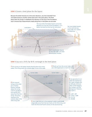
  • 51. for as long as possible. In other words, the strongest concrete is made with as little water as possible, retained inside the concrete for as long as possible. There are two basic ways to cure concrete. The first is to seal the water inside the concrete. On flat work, such as a basement floor, you can cover the floor with plastic sheets or spray on a special waterproof coating called curing compound. Do this several hours after the concrete has been finished and achieved its initial set. Make sure you seal up the edges of the plastic sheets; one way to do this is to place sand on top of the plastic around the perimeter of the slab. On vertical work, such as foundation walls, the moisture can be retained by keeping the forms in place for several days and just sealing the top, exposed edge (see the drawing at left on p. 43). The second basic strategy for curing concrete is to keep the exposed surface of the concrete damp. One way to do this is to cover the concrete with damp burlap. Make sure the burlap stays damp for several days. forming concrete Wet concrete weighs more than 4,000 lb. per cubic yard. When first mixed, it’s an amorphous blob that slumps and spreads out when poured. (Although the amount of slump varies with the percentage of water in the mix, it almost always has some slump.) When you pour this material into a form, the form has to contain the slump of the wet concrete. The concrete presses down and out, exerting tremendous pressure on the inside walls of the forms. This pressure can force forms to bulge out or fail catastrophically, like a burst dam. When you build forms for footings or foundation walls, you have to build them strong enough to contain this pressure. This pressure grows substantially with the height of the form and the quantity of concrete poured. Flatwork (sidewalks, floors, driveways, etc.), for example, sometimes requires several For footings 8 in. to 12 in. tall and slab-on-grade foundations, use 11⁄2-in.- thick lumber for the forms. Brace the stakes and tops of forms to keep them from spreading. 2×4s or 2×6s are nailed to small stakes driven into the ground every 4 ft. 44 Building the structure
  • 52. Plywood and 2×4 forms must be braced carefully to keep the bottoms from spreading. yards of concrete. But, because the forms are usually just 4 in. to 6 in. high, the thrusting forces of the concrete in these pours are relatively small. Typically, the forms for these structures are made out of 2×4s or 2×6s nailed to small stakes driven into the ground every 4 ft. or so. When the forms are 8 in. to 12 in. tall, as is the case for some footings and slab-on-grade foundations, 11⁄2-in.-thick lumber can still be used. However, the stakes have to be braced and the tops of the forms have to be connected to keep them from spreading. Forms for walls 16 in. to 24 in. high typically require 4-in.-thick panels built like the exterior walls of a house. These forms, built out of 2×4s and plywood, must be braced carefully. To keep the bottoms from spreading, carpenters often lay steel strapping on the footing, then wrap it up the outside of the forms and nail it securely. Forms for foundation walls taller than 24 in. can be erected with prefabri- cated panels, or they can be built on site with plywood and studs. Because of the tremendous pressure of the concrete, steel ties must be used to keep the walls from spreading, buckling, or blowing out altogether. If you need to form walls higher than 24 in., consider using a foundation subcontractor. He’ll have the forms, the hardware, and the experience to build a form that can contain the pressure of the concrete. Cubic Inches in a Cubic Yard The number 46,656 is not easy to remember and there’s no reason to do so. A yard is 36 in. and a cubic yard is 36 × 36 × 36, which is 46,656. Anytime you need this number for estimat- ing volume, just do the multi- plication and write it down. toP tiP Building foundAtions 45 1
  • 53. 46 Building the structure estimating concrete In the United States, ready-mix concrete is sold by the cubic yard. To estimate the amount needed for a pour, carefully measure the length, width, and depth of the area enclosed by the forms. After converting these measurements to a single measuring unit—usually feet or inches—multiply the length × the width × the depth to arrive at the volume in cubic feet or cubic inches. If you have the volume in cubic feet, divide by 27 (the number of cubic feet in a cubic yard) to convert to cubic yards. If you have the volume in cubic inches, divide by 46,656 (the number of cubic inches in a cubic yard) to convert to cubic yards. To make sure you don’t end up just short of concrete at the end of the pour, add about 10% for footings and 5% for walls. These conversions can be simplified by using a construction calculator. Aligning and bracing the forms When forming foundation walls, the layout often takes place at the footing level. After snapping chalklines on the top of the footing, set the bottoms of the forms on the lines, then brace them plumb. To ensure that the walls end up straight, brace the corner panels plumb first, then set up a string stretching from corner to corner. Brace the intermediate panels to the string. Anchor the bottom of the braces to stakes driven into the ground, and attach the tops of the braces to the panels with screws or nails. Set the bottoms of the forms on snapped lines, then brace them plumb. Anchor the braces to stakes driven into the ground and attach the tops to the panels.
  • 54. 1 Admixtures Concrete suppliers often offer chemical admixtures that can improve the work- ability or enhance the performance of concrete. The most common of these are air-entrainment admixtures. Other admixtures include chemicals that inhibit corrosion, reduce alkali-silica reaction, add bonding and damp-proofing properties, and provide coloring. Retarding admixtures are used in hot weather to slow down the setting rate of concrete. Accelerating admixtures are used in cold weather to increase the rate at which concrete gains strength. This means that the concrete has to be protected from freezing temperatures for a shorter period. Plasticizing admixtures make low-to-normal slump concrete more fluid without adding more water. This makes the concrete easier to place but doesn’t weaken it. This has given rise to a new use of the word “slump.” You can now order concrete with a “4-in. slump, plasticized to a 6-in. slump.” The 4-in. slump is the slump created by the water content and the additional 2 in. of slump is created by the admixture. Plasticizing admixtures work great for vertical pours, but they can cause problems for flat pours. This is because the effects of the plasticizing chemicals are temporary, lasting 30 to 60 minutes. When they wear off, the surface of the concrete can harden rather suddenly, making finishing difficult. When to Hire a Concrete Subcontractor Because of the stakes involved, builders often use concrete subcon- tractors. For large flat pours, such as a basement floor, experienced concrete masons can quickly pull the concrete flat, cut it level with a straightedge (often called a screed), and float the surface. Speed is of the essence, especially in hot weather. Concrete crews that specialize in flat work not only get the concrete placed and floated quickly but also have the skills and equipment to achieve very smooth finished surfaces. Large vertical pours, such as basement walls, require an enor- mous amount of concrete. Crews that specialize in basement walls have reusable manufactured forms that are engineered to contain the concrete. They have the experience to see how to bring in a truck close to the forms or to realize when they’re going to need to rent a con- crete pump. They’ve also developed the physical skills and the brawn needed to handle a chute or a hose full of concrete. Large concrete pours are often best left to specialists. Waiting for a subcontractor, however, presents its own set of problems. After you dig, form, and install steel in a footing, for example, you shouldn’t delay the pour. If it rains and the footing gets flooded, you’ll have to spend a lot more time getting the footing dry and removing silt that has washed into the trench. If you’re a custom builder or a remodeling contractor, it pays to be able to do small to medium pours “in house.” The key is to know what your crew can handle. This is something that you can determine only gradually, through experience. Starting with small pours, you can gradually develop the skills, acquire the tools, and gain the confidence needed for larger pours. way s o f w o r k i n g building foundations 47
  • 55. Permanent wood foundations, or PWFs, have been used in the United States since the 1960s. While these foundations require careful detailing, they can be built by any carpentry crew using standard framing techniques. The footings for these foundations are typically 8 in. of compacted gravel in a 16-in.-wide trench. A treated plate (usually a 2×10 or 2×12) is laid fl at on this bed of gravel. Then a 2×6 or 2×8 framed wall, sheathed with treated plywood, is nailed to the plate. PWFs are engineered systems and the details vary according to the type of foundation you’re building, the soil you encounter, and the design load of the house. Before starting a PWF, make sure you know and understand the design, and check with your local building offi cial to see what’s required in your area. Wood must be rated for foundations. Types 304 or 314 stainless-steel fasteners are generally required below grade. In some jurisdictions, other types of corrosion- resistant nail are permitted above grade. Permanent wood foundations (Pwfs) controlling water Controlling water is an essential part of these systems. First, you have to drain water from the footings, the base of the wall, and under the floor. Second, you must add a protective barrier to the outside of the foundation. On a sloping lot, use a gravity drain to move water away from the house. Drain water from the footing. Drain conveys water to daylight. PWF wall system Permanent wood foundations, or PWFs, have been used in the United States since the 1960s. While these foundations require careful detailing, they can be built by any carpentry crew using standard The footings for these foundations are typically 8 in. of compacted gravel in a 16-in.-wide trench. A treated plate (usually a 2×10 or 2×12) is laid fl at wall, sheathed with treated plywood, is nailed to PWFs are engineered systems and the details check with your local building offi cial to see what’s Wood must be rated for foundations. Types 304 or 314 stainless-steel fasteners are generally required below grade. In some jurisdictions, other types of corrosion- resistant nail are permitted above grade. Permanent wood foundations (Pwfs) 48 Building the structure
  • 56. Protective barrier The second part of the process is a protective barrier on the outside of the foundation. Because of the importance of keeping these systems dry, PWFs are not a good choice in very wet locations or where there’s a high water table. In basements, a concrete slab is poured inside the walls. This slab restrains the inward thrust that the soil exerts against the bottom of the walls. A treated wood floor, also built inside the walls, can be used in lieu of the concrete. In crawlspace foundations, there is less imbalanced fill between the inside and outside of the founda- tion wall. In these situations, the soil inside the wall is used to counteract pressure from the soil along the outside. Basements crawlspace foundations The framed floor resists inward pressure. 5 ft. to 7 ft. of soil presses against the wall system. Framing anchors are often specified for connections at the stud/ plate and joist/plate. Floor framing Poured slab Soil placed inside the foundation 12-in.-wide treated plywood holds the sheet in place to protect the top edge of the plastic. 6-mil plastic sheet to keep water from seeping into the frame PWF wall system PWF wall system PWF wall system Building foundAtions 49 1
  • 57. 50 CHAPTER 2 Framing Floors, walls, and ceilings aFTer comPleTing THe FoUndaTion, builders should have a level surface 8 in. or more above grade. Upon this surface, they begin the frame of the house, a structure that will defi ne the shape of the house and the layout of the rooms. Due to the size and complexity of house frames, this book devotes three chapters to their construction. This chapter concentrates on fl oors, walls, and ceilings. Chapters 3 and 4 will be devoted to framing roofs. The Three Functions of the Frame When you build the frame of a house, you need to do three things. First and foremost, you have to build a safe and sound structure. Second, you have to build a structure that accommodates almost all the subsequent work on the house. As you build the frame, then, you must look far into the future and provide for the needs of plumbers, drywall hangers, siders, fi nish carpenters, and other specialty trade contractors. Third, you should build a structure that meets acceptable standards of quality.
  • 58. 2 Framing floors, walls, and ceilings 51 Building a Safe and Sound Structure The primary responsibility of frame carpenters is to build a safe and durable structure. This aspect of frame carpentry is usually regulated by local building officials. Loads The frame supports both the weight of the building (dead loads) and the loads added by the inhabitants and the environment (live loads). The dead loads imposed on the walls of a house include the combined weight of floors, ceil- ings, and roof structures that bear on them and the weight of all the materi- als that cover those structures. The live loads include furniture, equipment, people, wind, snow, and seismic forces. Both dead and live loads vary from building to building. If a customer wants to roof her house in slate, for example, the dead load from the roof covering would be substantially more than if she opts to use asphalt shingles. The most important live loads are those generated by natural forces. Because those forces differ according to the climate and topography of the land, code requirements for frames vary from region to region. Different codes, in fact, often govern different areas within the same state. It’s essential to know and understand the code where you build. Built-in durability The frame not only has to have the strength to carry and resist loads, but it also has to endure in an often hostile environment. The two biggest threats to wood-framed houses are water and fire. Although the first defenses against rainwater intrusion are the materials that are later installed on the exterior of the frame, the frame itself contains built-in features that help the building resist these destructive forces. One basic built-in feature is the shape of the roof. A pitched roof helps move rainwater down and off the house. Eaves and rakes provide even more built-in protection because they keep most of the runoff from the roof away from the outside of the walls. Another built-in feature that resists the destructive force of water is the use of treated wood wherever the wood is attached to masonry or concrete. Masonry and concrete can absorb water through capillary action, the same mechanism by which a sponge absorbs water. In hot, humid weather, moisture from the air also condenses on concrete and masonry surfaces (which often stay cooler than the ambient temperature). Over time, this moisture can cause untreated wood to rot or attract termites. Because treated wood does not deteriorate in the presence of water, it’s required by most building codes in these locations. A house is subject to dead loads and live loads. A pitched roof provides built-in protection from water.