


Time study part 2
- 3. HELL O! You know who I am. You guys must know what to call me. And I am here to FINISH what my comrade has started.
- 5. MOVING ON! Step 5 for Method Study RECORDING is facts relating to the existing method.
- 6. Records are useful to make BEFORE AFTER& comparison to assess the effectiveness of the proposed improved method.
- 7. Charts Diagrams Macro Motion Charts Micro Motion Charts RECORDING TECHNIQUES FOR METHOD STUDY can be measured can’t be measured through stop watch.
- 8. Method Study Symbols D OPERATION INSPECTION TRANSPORTATION DELAY STORAGE I will send you soft copy of these symbols through our group chat. FOR OUR FUTURE REFERENCE
- 9. MACRO MOTION CHARTS Operations Process Chart Flow Process Chart Multiple Activity ChartTwo Handed Process Chart OPC FPC MACTHPC
- 10. MACRO MOTION CHARTS OPC Operations Process Chart A.K.A. Outline Process Chart An operation process that gives the bird’s eye view of the whole process by recording only the major activities and inspections involved in the process. Is helpful to the complete of the operations and inspections in the process.
- 11. TO ILLUSTRATE Making a cheese sandwich OPC uses only two symbols, i.e., operation and inspection. REMEMBER THUS NOT INCLUDED NOT INCLUDED
- 12. MACRO MOTION CHARTS Flow Process Chart It is the amplification of the OPC in which operations, inspection, storage, delay, and transportation are represented.FPC D FPC is useful: to reduce the distance travelled by men (or materials). to avoid waiting time and unnecessary delays. to reduce the cycle time by combining or eliminating operations. to fix up the sequence of operations. to relocate the inspection stages.
- 13. MACRO MOTION CHARTS Flow Process Chart It is the amplification of the OPC in which operations, inspection, storage, delay, and transportation are represented.FPC 3 Types of FPC: MATERIAL TYPE MAN TYPE EQUIPMENT TYPEooooooooooom!!
- 14. TO ILLUSTRATE Egg trays production Material type flow process
- 15. TO ILLUSTRATE Supplier invoice processing Man type flow process
- 16. MACRO MOTION CHARTS Two Handed Process Chart Is the most detailed type of flow chart in which the activities of the workers hands are recorded in relation to one another. THPC Application of THPC are: to visualize the complete sequence of activities in a repetitive task. to study the work station layout.
- 17. TO ILLUSTRATE
- 18. MACRO MOTION CHARTS Multiple Activity Chart It is a chart where activities of more than subject (worker or equipment) are each recorded on a common time scale to show their inter- relationship. MAC MAC is made: to study idle time of the man and machines; to determine number of machines handled by one operator, and to determine number of operators required in teamwork to perform the given job.
- 19. TO ILLUSTRATE Assumption: Operator have access to 1 Washer and 1 Dryer.
- 20. MACRO MOTION CHARTS Operations Process Chart Operations and Inspection. Flow Process Chart Operations, inspection, storage, delay, and transportation. Multiple Activity Chart Relationship between subjects. (workers or equipment). Two Handed Process Chart Left and Right hands. OPC FPC MACTHPC Review
- 21. 01 02 Flow Diagram String Diagram Diagrams Used in Method Study
- 22. 01 Is a drawing of the working area, showing the location of the various activities identified by their numbered symbols and are associated with particular flow process chart either man type or machine type. Flow Diagram Diagrams Used in Method Study
- 23. The layout of the workplace is drawn to scale.Relative positions of the machine tools, work benches, and inspection benches are marked on the scale.Path followed by the subject under study is tracked by drawing lines.Each movement is serially numbered and indicated by arrow for direction.Different colors are used to denote different types of movements. TO ILLUSTRATEProcedures to make the flow diagram:
- 24. 02 Is a scale layout drawing on which, length of a string is used to record the extent as well as the pattern of movement of a worker working within a limited area during a certain period of time. String Diagram Diagrams Used in Method Study One of the most valuable feature of the string diagram is the actual distance travelled during the period of study to be calculated by relating the length of the thread used to the scale of drawing. LAYOUT A LAYOUT B THUSIt helps to make a very effective comparison between different layouts or methods of doing job in terms of the travelling involved. 1 meter2.5 meter
- 25. TO ILLUSTRATE A layout of the work place of factory is drawn to scale on the soft board. Pins are fixed into boards to mark the locations of work stations, pins are also driven at the turning points of the routes. A measured length of thread is taken to trace the movements (path). Procedures to draw string diagram:
- 26. MICRO MOTION STUDY CHART MICRO MOTION STUDY CHART
- 27. FIRST WE MUST KNOW FUNDAMENTAL HAND MOTIONS (THERBLIG ANALYSIS) Therblig: the system of symbols that represent every elementary of hand / arm and eye movements. Therblig was the creation of Frank Bunker Gilberth 1868 - 1924
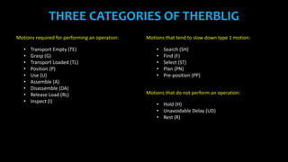
- 28. THREE CATEGORIES OF THERBLIG Motions required for performing an operation: • Transport Empty (TE) • Grasp (G) • Transport Loaded (TL) • Position (P) • Use (U) • Assemble (A) • Disassemble (DA) • Release Load (RL) • Inspect (I) Motions that tend to slow down type 1 motion: • Search (SH) • Find (F) • Select (ST) • Plan (PN) • Pre-position (PP) Motions that do not perform an operation: • Hold (H) • Unavoidable Delay (UD) • Rest (R)
- 30. MICRO MOTION STUDY USES SIMULTANEOUS MOTION CYCLE CHART (SIMO CHART)
- 31. SIMO CHART Often based on film analysis used to record simultaneously on a common time scale the Therblig or group of Therbligs performed by different parts of the body of one or more operators. the time scale is represented in winks (1/2000 of a minute). Used primarily for operations of short duration, often performed with extreme rapidity. it is generally necessary to compile them from films made of the operation which can be stopped at any point or projected in slow motion.
- 32. SIMO CHART Basic steps • See motions made by the operator’s right and left hands • Notice what the fingers of each hand do • Detect where one motion ends and another begins • Judge the lengths of motions • Estimate times of the motions
- 33. BEARWITH ME ANG HABA EH
- 34. MOTION STUDY Is part of method study where analysis of the motion of an operator or work will be studied
- 35. PRINCIPLES OF MOTION STUDY A. Use of the human body B. Arrangement of workplace C. Design of tools and equipment By Barnes, Maynard, and others.
- 36. USE OF HUMAN BODY 1. The two hands should begin and complete their movements at the same time. 2. The two hands should not be idle at the same time except during period of rest. 3. Motions of the arms should be made simultaneously. 4. Hand and body motions should be made at the lowest classification at which it is possible to do the work satisfactorily. 5. Momentum should be employed to help the worker, but should be reduced to a minimum whenever it has to be overcome by muscular effort. 6. Continuous curved movements are to be preferred to straight line motions involving sudden and changed in directions. 7. ‘Ballistic’ (i.e. free swinging) movements are faster, easier and more accurate than restricted or controlled movements. 8. Rhythm is essential to the smooth and automatic performance of a repetitive operation. The work should be arranged to permit easy and natural rhythm wherever possible. 9. Work should be arranged so that eye movement are confined to a comfortable area, without the need for frequent changes of focus
- 37. 1. Definite and fixed stations should be provided for all tools and materials to permit habit formation. 2. Tools and materials should be pre-positioned to reduce searching. 3. Gravity fed, bins and containers should be used to deliver the materials as close to the point of use as possible. 4. Tools, materials and controls should be located within a maximum working are and as near to the worker as possible. 5. Materials and tools should be arranged to permit the best sequence of motions. 6. ‘Drop deliveries’ or ejectors should be used wherever possible, so that the operative does not have to use his hands to dispose of finished parts. 7. Provision should be made for adequate lightning, and a chair of type and height to permit good posture should be provided. The height of the workplace and seat should be arranged to allow alternate standing and seating. ARRANGEMENT OF THE WORKPLACE
- 38. DESIGN OF TOOLS AND EQUIPMENT 1. The color of the workplace should contrast with that of work and thus reduce eye fatigue. 2. The hands should be relieved of all work of ‘holding’ the work piece where this can be done by a jig or fixture or foot operated device. 3. Two or more tools should be combined where possible. 4. Where each finger performs some specific movement, as in typewriting, the load should be distributed in accordance with inherent capacities of the fingers. 5. Handles such as those used on screw drivers and cranks should be designed to permit maximum surface of the hand to come in contact with the handle. 6. Levers, cross bars and wheel bars should be in such position that operator can manipulate them with least body change and with greatest mechanical advantage.
- 39. TIME STUDY The application of techniques designed to establish the time for a qualified worker to carry out a specified job at a defined level of performance.
- 40. STEPS IN MAKING TIME STUDY 1. Select the work to be studied. 2. Obtain and record all the information available about the job, the operator and the working conditions likely to affect the time study work. 3. Breakdown the operation into elements. An element is an instinct part of a specified activity composed of one or more fundamental motions selected for convenience of observation and timing. 4. Measure the time by means of a stop watch taken by the operator to perform each element of the operation. 5. At the same time, assess the operators effective speed of work relative to the observer’s concept of ‘normal’ speed. This is called performance rating. 6. Adjust the observed time by rating factor to obtain normal time for each element Normal time = Observed time x Rating 100
- 41. STEPS IN MAKING TIME STUDY 7. Add the suitable allowances to compensate for fatigue, personal needs, contingencies, etc. to give standard time for each element. 8. Compute allowed time for the entire job by adding elemental standard times considering frequency of occurrence of each element. 9. Make a detailed job description describing the method for which the standard time is established. 10. Test and review standards wherever necessary.
- 42. COMPUTATION OF STANDARD TIME Standard time is the time allowed to an operator to carry out the specified task under specified conditions and defined level of performance.
- 43. Standard time = Normal time + Various allowances Normal time = Observed time x Rating 100 OT – Observed Time PRF – Performance Rating Factor NT – Normal Time PA – Process Allowances RPA – Rest and Personal Allowances SA – Special Allowances PoA – Policy Allowances
- 49. I’m done. (-, – )…zzzZZZ