Gear trains
•Download as PPSX, PDF•
92 likes•49,073 views

Unit 7-gear trains, Kinematics of machines of VTU Syllabus prepared by Hareesha N Gowda, Asst. Prof, Dayananda Sagar College of Engg, Blore. Please write to hareeshang@gmail.com for suggestions and criticisms.
Report
Share
Related slideshows

Gear trains
- 1. 1/27/2014 Hareesha N Gowda, Asst. Prof, DSCE, BLore78 1
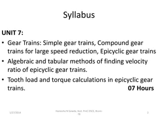
- 2. Syllabus UNIT 7: • Gear Trains: Simple gear trains, Compound gear trains for large speed reduction, Epicyclic gear trains • Algebraic and tabular methods of finding velocity ratio of epicyclic gear trains. • Tooth load and torque calculations in epicyclic gear trains. 07 Hours 1/27/2014 Hareesha N Gowda, Asst. Prof, DSCE, BLore78 2
- 3. Introduction • Sometimes, two or more gears are made to mesh with each other to transmit power from one shaft to another. Such a combination is called gear train or train of toothed wheels. • The nature of the train used depends upon the velocity ratio required and the relative position of the axes of shafts. • A gear train may consist of spur, bevel or spiral gears. 1/27/2014 Hareesha N Gowda, Asst. Prof, DSCE, BLore78 3
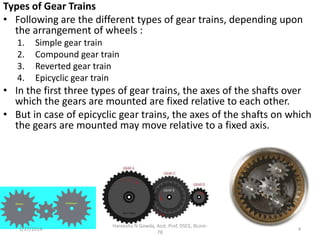
- 4. Types of Gear Trains • Following are the different types of gear trains, depending upon the arrangement of wheels : 1. 2. 3. 4. Simple gear train Compound gear train Reverted gear train Epicyclic gear train • In the first three types of gear trains, the axes of the shafts over which the gears are mounted are fixed relative to each other. • But in case of epicyclic gear trains, the axes of the shafts on which the gears are mounted may move relative to a fixed axis. 1/27/2014 Hareesha N Gowda, Asst. Prof, DSCE, BLore78 4
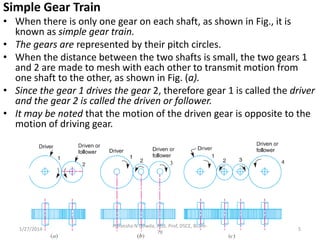
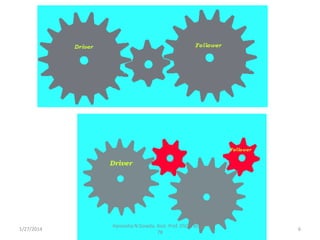
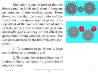
- 5. Simple Gear Train • When there is only one gear on each shaft, as shown in Fig., it is known as simple gear train. • The gears are represented by their pitch circles. • When the distance between the two shafts is small, the two gears 1 and 2 are made to mesh with each other to transmit motion from one shaft to the other, as shown in Fig. (a). • Since the gear 1 drives the gear 2, therefore gear 1 is called the driver and the gear 2 is called the driven or follower. • It may be noted that the motion of the driven gear is opposite to the motion of driving gear. 1/27/2014 Hareesha N Gowda, Asst. Prof, DSCE, BLore78 5
- 6. 1/27/2014 Hareesha N Gowda, Asst. Prof, DSCE, BLore78 6
- 7. 1/27/2014 Hareesha N Gowda, Asst. Prof, DSCE, BLore78 7
- 8. 1/27/2014 Hareesha N Gowda, Asst. Prof, DSCE, BLore78 8
- 9. 1/27/2014 Hareesha N Gowda, Asst. Prof, DSCE, BLore78 9
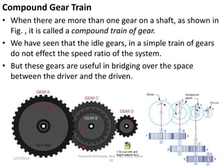
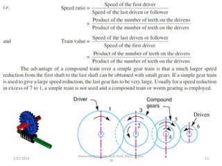
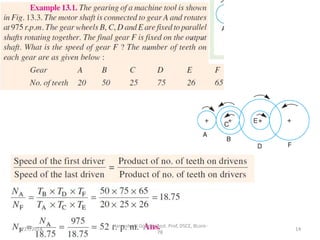
- 10. Compound Gear Train • When there are more than one gear on a shaft, as shown in Fig. , it is called a compound train of gear. • We have seen that the idle gears, in a simple train of gears do not effect the speed ratio of the system. • But these gears are useful in bridging over the space between the driver and the driven. 1/27/2014 Hareesha N Gowda, Asst. Prof, DSCE, BLore78 10
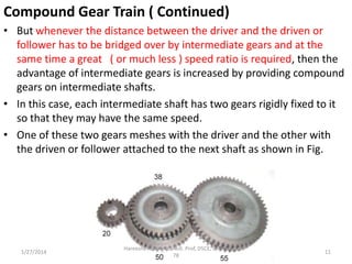
- 11. Compound Gear Train ( Continued) • But whenever the distance between the driver and the driven or follower has to be bridged over by intermediate gears and at the same time a great ( or much less ) speed ratio is required, then the advantage of intermediate gears is increased by providing compound gears on intermediate shafts. • In this case, each intermediate shaft has two gears rigidly fixed to it so that they may have the same speed. • One of these two gears meshes with the driver and the other with the driven or follower attached to the next shaft as shown in Fig. 1/27/2014 Hareesha N Gowda, Asst. Prof, DSCE, BLore78 11
- 12. 1/27/2014 Hareesha N Gowda, Asst. Prof, DSCE, BLore78 12
- 13. 1/27/2014 Hareesha N Gowda, Asst. Prof, DSCE, BLore78 13
- 14. 1/27/2014 Hareesha N Gowda, Asst. Prof, DSCE, BLore78 14
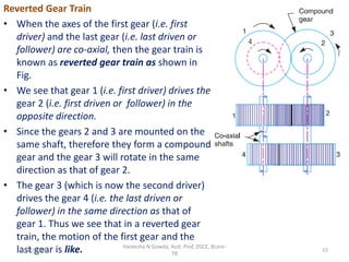
- 15. Reverted Gear Train • When the axes of the first gear (i.e. first driver) and the last gear (i.e. last driven or follower) are co-axial, then the gear train is known as reverted gear train as shown in Fig. • We see that gear 1 (i.e. first driver) drives the gear 2 (i.e. first driven or follower) in the opposite direction. • Since the gears 2 and 3 are mounted on the same shaft, therefore they form a compound gear and the gear 3 will rotate in the same direction as that of gear 2. • The gear 3 (which is now the second driver) drives the gear 4 (i.e. the last driven or follower) in the same direction as that of gear 1. Thus we see that in a reverted gear train, the motion of the first gear and the Hareesha N Gowda, Asst. Prof, DSCE, BLore1/27/2014 last gear is like. 78 15
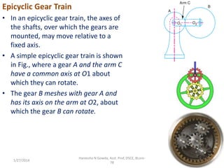
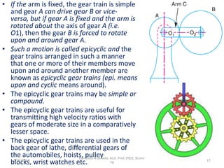
- 16. Epicyclic Gear Train • In an epicyclic gear train, the axes of the shafts, over which the gears are mounted, may move relative to a fixed axis. • A simple epicyclic gear train is shown in Fig., where a gear A and the arm C have a common axis at O1 about which they can rotate. • The gear B meshes with gear A and has its axis on the arm at O2, about which the gear B can rotate. 1/27/2014 Hareesha N Gowda, Asst. Prof, DSCE, BLore78 16
- 17. • If the arm is fixed, the gear train is simple and gear A can drive gear B or viceversa, but if gear A is fixed and the arm is rotated about the axis of gear A (i.e. O1), then the gear B is forced to rotate upon and around gear A. • Such a motion is called epicyclic and the gear trains arranged in such a manner that one or more of their members move upon and around another member are known as epicyclic gear trains (epi. means upon and cyclic means around). • The epicyclic gear trains may be simple or compound. • The epicyclic gear trains are useful for transmitting high velocity ratios with gears of moderate size in a comparatively lesser space. • The epicyclic gear trains are used in the back gear of lathe, differential gears of the automobiles, hoists, pulley Asst. Prof, DSCE, BLoreHareesha N Gowda, 1/27/2014 78 blocks, wrist watches etc. 17
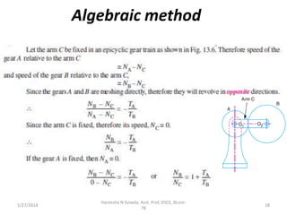
- 18. Algebraic method 1/27/2014 Hareesha N Gowda, Asst. Prof, DSCE, BLore78 18
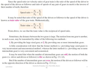
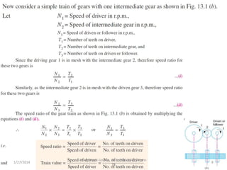
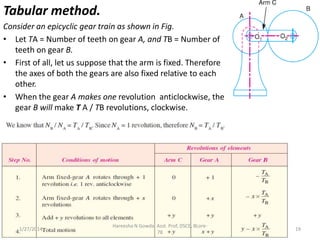
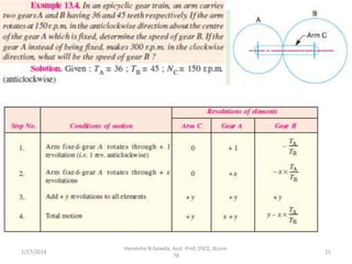
- 19. Tabular method. Consider an epicyclic gear train as shown in Fig. • Let TA = Number of teeth on gear A, and TB = Number of teeth on gear B. • First of all, let us suppose that the arm is fixed. Therefore the axes of both the gears are also fixed relative to each other. • When the gear A makes one revolution anticlockwise, the gear B will make T A / TB revolutions, clockwise. 1/27/2014 Hareesha N Gowda, Asst. Prof, DSCE, BLore78 19
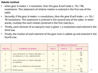
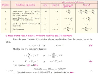
- 20. Tabular method. • when gear A makes + 1 revolution, then the gear B will make (– TA / TB) revolutions. This statement of relative motion is entered in the first row of the table. • Secondly, if the gear A makes + x revolutions, then the gear B will make – x × TA / TB revolutions. This statement is entered in the second row of the table. In other words, multiply the each motion (entered in the first row) by x. • Thirdly, each element of an epicyclic train is given + y revolutions and entered in the third row. • Finally, the motion of each element of the gear train is added up and entered in the fourth row. 1/27/2014 Hareesha N Gowda, Asst. Prof, DSCE, BLore78 20
- 21. 1/27/2014 Hareesha N Gowda, Asst. Prof, DSCE, BLore78 21
- 22. 1/27/2014 Hareesha N Gowda, Asst. Prof, DSCE, BLore78 22
- 23. 1/27/2014 Hareesha N Gowda, Asst. Prof, DSCE, BLore78 23
- 24. 1/27/2014 Hareesha N Gowda, Asst. Prof, DSCE, BLore78 24
- 25. 1/27/2014 Hareesha N Gowda, Asst. Prof, DSCE, BLore78 25