


Wimax 4
- 1. WIMAX
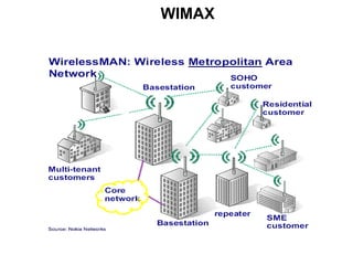
- 2. WIMAX WIMAX ( Worldwide Interoperability for Microwave Access ): Protocol of communication network without wire, based on the standard IEEE 802.16 Allows communications over long distances than WiFi, and a greater bandwidth. Cover approximately 40km. Field of application : Better price points for both home and business customers. WIMAX allow competitors joint access to any subscriber in areas without preexisting physical cable or telephone networks would allow gamers access to ad hoc local networks of other players with the same gear- without any internet access.
- 3. Introduction Goal of WIMAX: Provide high-speed Internet access to home and business subscribers, without wires. Frequency range: 10-66 GHz and sub 11 GHz Supports: Legacy voice systems Voice over IP TCP/IP Applications with different QoS requirements.
- 4. Introduction 802.16 consists of the access point, BS(Base Station) and SSs (Subscriber Stations). All data traffic goes through the BS, and the BS control the allocation of bandwidth on the radio channel.
- 5. Introduction During a communication, all the information coming from a SS go to the BS and are retransmit to the right SS. Base stations (BS) can handle thousands of subscriber stations (SS). Two type of link are defined : The downlink: From the BS to the SS. The uplink: From the SS to the BS.
- 6. Introduction Infrastructure of WIMAX A WIMAX tower: similar in concept to a cell-phone tower. A single WIMAX tower can provide coverage to a very large area (~8,000 km). A WIMAX receiver : The receiver and antenna could be a small box or PCMCIA card, or could be built into a laptop.
- 7. Introduction A WIMAX tower An example of WIMAX receiver : PCMCIA card
- 8. PLAN I Transmission of the data II ARQ III Scheduling
- 9. PLAN I Transmission of the data II ARQ III Scheduling
- 10. I Transmission of the data 1 Mac and physical layer s 2 S tructure of a SDU 3 structure of a PDU 4 fragmentation and packing
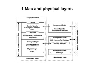
- 11. The physical level: Specify the frequencies diagram of modulation synchronizations speeds, techniques of cutting in the time (of type TDMA: Time Division Multiple Access) techniques of detection and correction of error . 1 Mac and physical layer s
- 12. 1 Mac and physical layer s The MAC level : Located at the top of the physical level, it manages the allowance of the slots and uses the method Rammed-tdma. The interface of communication with the applications : this layer concentrates on the management of level IP and the encapsulation of packages IP in the screen adapted to the section of time.
- 13. 1 Mac and physical layer s The MAC is comprised of three sublayers. The Service Specific Convergence Sublayer (CS) provides any transformation or mapping of external network data, received through the CS service access point (SAP), into MAC SDUs received by the MAC Common Part Sublayer (MAC CPS) through the MAC SAP.
- 14. 1 Mac and physical layer s
- 15. 1 Mac and physical layer s
- 16. I Transmission of the data 1 Mac and physical layer s 2 S tructure of a SDU 3 structure of a PDU 4 fragmentation and packing
- 17. 2 structur e of a SDU Higher-layer PDUs shall be encapsulated in the MAC SDU format. For some payload protocols, each payload consists of an 8-bit payload header suppression index (PHSI) field followed by actual payload. Other protocols map the higher layer PDU directly to the MAC SDU. A value of zero in the PHSI indicates no payload header suppression has been applied to the PDU .
- 18. I Transmission of the data 1 Mac and physical layer s 2 S tructure of a SDU 3 structure of a PDU 4 fragmentation and packing
- 19. 3 S tructure of a M PDU MSB LSB Generic MAC header Payload (optional) CRC (optional) The maximum length of the MAC PDU is 2048 bytes, including header, payload, and Cyclic Redundancy Check (CRC). 6 bytes Variable 4 bytes The size of the payload is variable, the payload can contain either data or management message.
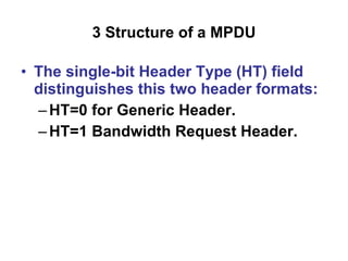
- 20. 3 S tructure of a M PDU Two MAC header formats are defined: Generic MAC Header that begins each MAC PDU containing either MAC management messages or CS data. Bandwidth Request Header used by the SS to request additional bandwidth. The single-bit Header Type (HT) field distinguishes this two header formats: HT=0 for Generic Header. HT=1 Bandwidth Request Header. Two MAC header formats are defined: Generic MAC Header that begins each MAC PDU containing either MAC management messages or CS data. Bandwidth Request Header used by the SS to request additional bandwidth.
- 21. 3 S tructure of a M PDU The single-bit Header Type (HT) field distinguishes this two header formats: HT=0 for Generic Header. HT=1 Bandwidth Request Header.
- 22. I Transmission of the data 1 Mac and physical layer s 2 S tructure of a SDU 3 structure of a PDU 4 fragmentation and packing
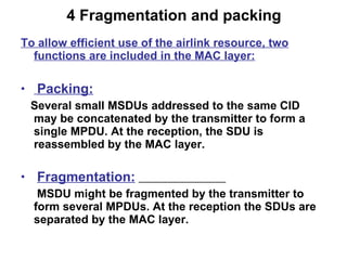
- 23. 4 Fragmentation and packing To allow efficient use of the airlink resource, two functions are included in the MAC layer: Packing: Several small MSDUs addressed to the same CID may be concatenated by the transmitter to form a single MPDU. At the reception, the SDU is reassembled by the MAC layer. Fragmentation: MSDU might be fragmented by the transmitter to form several MPDUs. At the reception the SDUs are separated by the MAC layer.
- 24. 4 Fragmentation and packing Reasons: Lack of the frame time when allocating the air time to the given MSDU High BER that requires employing integrity check for smaller data blocks
- 25. 4 Fragmentation and packing The number of fragments can not be more than 16. When created, the MAC payload (MPDU) are assigned by: - Fragment Serial Number (FSN) with possible value 0 to 15. - Fragment Control code (FC) with the following meaning: o 00 = non-fragmented MPDU. o 01 = last fragment. o 10 = first fragment. o 11 = continuing (middle) fragment. The FSN is always transmitted within the same MAC message as the fragment data.
- 26. 4 Fragmentation and packing The sequence number allows the SS to recreate the original payload and to detect the loss of any intermediate packets. Upon loss, the SS shall discard all MAC PDUs on the connection until a new first fragment is detected or a non fragmented MAC PDU is detected.
- 27. 4 Fragmentation and packing If packing is turned on for a connection, the MAC may pack multiple MAC SDUs into a single MAC PDU. Packing makes use of the connection attribute indicating whether the connection caries fixed-length or variable-length packets. The transmitting side has full discretion whether or not to pack a group of MAC SDUs in a single MAC PDU .
- 28. 4 Fragmentation and packing Decrease the MAC overhead
- 29. 4 Fragmentation and packing Packing and fragmentation can occur in the same PDU .
- 30. Summarize PDU which has started in the previous TC packet First PDU which starts in this TC packet Second PDU which starts in this TC packet SDU 1 SDU 2 SDU 3 SDU 4 PDU 1 PDU 2 PDU 3 NO fragmentation & NO packing Packing Fragmentation MAC SDUs MAC PDUs P FEC 1 FEC 2 FEC 3 Preamble TC PDUs BURST FEC encoding
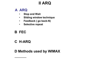
- 31. II ARQ A ARQ Stop and Wait Sliding window technique Feedback ( go back-N) Selective repeat B FEC C H-ARQ D Methods used by WIMAX
- 32. II ARQ Three methods are employed to makes the data transmission reliable in a unreliable connection ( airlink): ARQ ( automatic repeat request) FEC (Forward Error Correcting) H-ARQ (hybrid ARQ= ARQ+FEC)
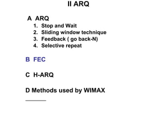
- 33. II ARQ A ARQ Stop and Wait Sliding window technique Feedback ( go back-N) Selective repeat B FEC C H-ARQ D Methods used by WIMAX
- 34. II ARQ Three methods are employed for the ARQ wireless transmissions: Stop and Wait Feedback ( go back-N) Selective repeat Both feedback and selective algorithm are based on sliding window technique
- 35. II ARQ A ARQ Stop and Wait Sliding window technique Feedback ( go back-N) Selective repeat B FEC C H-ARQ D Methods used by WIMAX
- 36. Stop and Wait to each reception of a package, the receiver sends a particular message (ACK) to show reception. the transmitter preserves a copy of the emitted package and await the reception of the acknowledgement. after a certain time (time out), the package is retransmitted (and the transmitter waits again ).
- 37. Stop and Wait retransmission Transmitting Data 1 3 2 3 Time Received Data 1 2 3 Time ACK ACK NAK Output Data 1 2 3 Time Error ACK: Acknowledge NAK: Negative ACK
- 38. Stop and Wait Disadvantages of this method: Problem of acknowledgement of delivery transmission not very effective time between the emission of two packages Transmissions on the network in only one direction at the same time => use of the sliding window technique
- 39. II ARQ A ARQ Stop and Wait Sliding window technique Feedback ( go back-N) Selective repeat B FEC C H-ARQ D Methods used by WIMAX
- 40. One emits several packages before awaiting an acknowledgement. The number of packages is defined by the size of the window. In each acknowledgement, the window shifts (slips). The sliding window technique:
- 41. II ARQ The sliding window technique Without window With a sliding window size=0 (stop and wait) size=3 Transmitter Receptor Transmitter Receptor
- 42. II ARQ A ARQ Stop and Wait Sliding window technique Feedback ( go back-N) Selective repeat B FEC C H-ARQ D Methods used by WIMAX
- 43. Feedback ( go back-N) Based on the sliding window technique When an MPDU is lost, the transmitter is required to retransmit all the PDU starting from first MPDU was lost Disadvantage of this method: Very bandwidth inefficient: some frames may be repeated several times while there are well received.
- 44. Feedback ( go back-N) 1 Time NAK Time Error Go-back 3 2 3 4 5 3 4 4 5 6 7 5 1 2 3 4 4 5 Error NAK Go-back 5 1 2 3 4 4 5
- 45. II ARQ A ARQ Stop and Wait Sliding window technique Feedback ( go back-N) Selective repeat B FEC C H-ARQ D Methods used by WIMAX
- 46. Selective repeat Based on the sliding window technique Only the lost MPDU is retransmitted
- 47. Selective repeat 1 Time NAK Error Retransmission 2 3 4 5 3 6 7 8 9 7 1 Time 2 4 3 6 8 7 Error NAK Retransmission 5 9 1 Time 2 4 3 6 8 7 5 9 1 Time 2 4 3 6 8 7 5 9
- 48. II ARQ A ARQ Stop and Wait Sliding window technique Feedback ( go back-N) Selective repeat B FEC C H-ARQ D Methods used by WIMAX
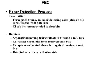
- 49. FEC Error Detection Process: Transmitter For a given frame, an error-detecting code (check bits) is calculated from data bits Check bits are appended to data bits Receiver Separates incoming frame into data bits and check bits Calculates check bits from received data bits Compares calculated check bits against received check bits Detected error occurs if mismatch
- 50. FEC Transmitter Forward error correction (FEC) encoder maps each k-bit block into an n-bit block codeword. Codeword is transmitted. Receiver Incoming signal is demodulated Block passed through an FEC decoder
- 51. FEC
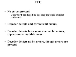
- 52. No errors present Codeword produced by decoder matches original codeword. Decoder detects and corrects bit errors. Decoder detects but cannot correct bit errors; reports uncorrectable error. Decoder detects no bit errors, though errors are present FEC
- 53. II ARQ A ARQ Stop and Wait Sliding window technique Feedback ( go back-N) Selective repeat B FEC C H-ARQ D Methods used by WIMAX
- 54. H-ARQ H-ARQ= FEC+ARQ FEC: turbo codes/ convolutional codes/ block codes/… ARQ: selective repeat (SR) / stop and wait (SAW)/ go-back-N (GBN)
- 55. II ARQ A ARQ Stop and Wait Sliding window technique Feedback ( go back-N) Selective repeat B FEC C H-ARQ D Methods used by WIMAX
- 56. Methods used by WIMAX ARQ mechanism is an optional part of the MAC layer in WIMAX. WIMAX can use ARQ ,FEC or H-ARQ.
- 57. 1 ARQ : Uses the sliding window technique: Selective repeat is selected by default Feedback algorithm in specified case More details: ARQ parameters shall be specified and negotiated during connection creation or change A connection can not have a mixture of ARQ and non-ARQ traffic The ARQ feedback information can be sent as a standalone MAC management message on the appropriate basic management connection or piggybacked on an existing connection ARQ feedback cannot be fragmented. Methods used by WIMAX
- 58. Transmitter state 1 ARQ :
- 59. Receiver state 1 ARQ :
- 60. 2 FEC: Methods used by WIMAX 802.16 specifies the concatenation of a Reed-Solomon (RS) outer code and a rate-compatible convolutional inner code, on both uplink and downlink. The encoding is performed by first passing the data in block format through the RS encoder and then passing it through a zero-terminating convolutional encoder. Turbo convolutional codes (TC) and Turbo Block (TB) codes are specified as optional FEC schemes in the standard. Low density parity check (LDPC) codes are a new type of FEC codes that are gaining in popularity and might be specified as optional FEC scheme in 802.16e version
- 61. 3 H-ARQ : H-ARQ schema is basically a stop and wait protocol: Each H-ARQ packet is encoded and 4 subpackets are generated from the encoded result The transmitter shall send the packet labeled ’00’ at he fist transmission Then the receiver attempts to decode the original encoder packet If it succeeds the receiver sends an ACK to the transmitter so that the transmitter stops sending additional subpackets. Otherwise the transmitter sends a NACK and the transmitter may send one among the fourth subpackets. Methods used by WIMAX
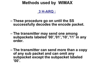
- 62. Methods used by WIMAX 3 H-ARQ : These procedure go on until the SS successfully decodes the encode packet. The transmitter may send one among subpackets labeled ’00’,’01’,’10’,’11’ in any order. The transmitter can send more than a copy of any sub packet and can omit any subpacket except the subpacket labeled ’00’.
- 63. III Downlink/Uplink Scheduling Radio resources have to be scheduled according to the QoS (Quality of Service) parameters WIMAX Downlink scheduling: the flows are simply multiplexed the standard scheduling algorithms can be used : WRR (Weighted Round Robin) VT (Virtual Time) WFQ (Weighted Fair Queueing) WFFQ (Worst-case Fair weighted Fair Queueing) DRR (Deficit Round Robin) DDRR (Distributed Deficit Round Robin)
- 64. III Downlink/Uplink Scheduling Plan A Downlink Scheduling B Uplink Scheduling
- 65. III Downlink/Uplink Scheduling Plan A Downlink Scheduling B Uplink Scheduling
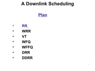
- 66. A Downlink Scheduling Plan RR WRR VT WFQ WFFQ DRR DDRR
- 67. Plan RR WRR VT WFQ WFFQ DRR DDRR A Downlink Scheduling
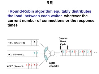
- 68. RR 1 1 1 VCC 1 (Source 1) 2 2 VCC 2 (Source 2) 3 3 3 VCC 3 (Source 3) 3 3 1 2 3 1 1 2 WRR scheduler Counter Reset Cycle 1 3 2 2 3 3 … . Round-Robin algorithm equitably distributes the load between each waiter whatever the current number of connections or the response times
- 69. RR This algorithm is adapted if the waiters of the cluster have the same processing capacities if not, certain waiters are likely to receive more requests than they can treat. Some while others will use only part of their resources. The WRR algorithm solves this problem.
- 70. Plan RR WRR VT WFQ WFFQ DRR DDRR A Downlink Scheduling
- 71. WRR The WRR algorithm is based on the Round Robin algorithm but it takes into account the processing capacity of each waiter. The administrators manually assign a coefficient of performance to each waiter. ( 1, 2 and 3 in the example). Counter Reset Cycle Coefficients of performance … . 1 1 1 VCC 1 (Source 1) 2 2 VCC 2 (Source 2) 3 3 3 VCC 3 (Source 3) 3 3 2 1 3 1 2 3 1 1 1 2 3 3 3 3 3 WRR scheduler
- 72. A sequence of scheduling is generated automatically according to this value. The requests are then assigned to the various waiters according to a sequence of alternate repetition WRR VCC 2 (Source 2) VCC 3 (Source 3) …… . 1 1 1 VCC 1 (Source 1) 2 2 3 3 3 3 3 2 1 3 1 2 3 1 1 1 2 3 3 3 3 3 WRR scheduler Counter Reset Cycle Sequence of scheduling
- 73. Plan RR WRR VT WFQ WFFQ DRR DDRR A Downlink Scheduling
- 74. VT
- 75. VT VT : aims to emulate the TDM (Time Division Multiplexing) connection 1 : reserves 50% of the link bandwidth connection 2, 3 : reserves 20% of the link bandwidth Connection 1 Average inter-arrival : 2 units Connection 2 Average inter-arrival : 5 units Connection 3 Average inter-arrival : 5 units First-Come-First-Served service order Virtual times Virtual Clock service order
- 76. A Downlink Scheduling Plan RR WRR VT WFQ WFFQ DRR DDRR
- 77. It is not practical to have one queue for each conversation so the WFQ employs a hashing algorithm which divides the traffic over a limited number of queues to be selected by the user or fixed by default. WFQ is like having several doors. When a packet arrives it is classified by the classifier and assigned to one of the doors. The door is the entry to a queue that is served together with some other in a weighted round-robin order. This way the service is 'fair' for every queue. WFQ
- 78. The packet arrives, then the classifier reads its header. Calculates a number between "1" and "number of queues“ by using information contained on the header (source address ,destination address, ip precedence, protocol, ...) Then, it locates the packet in the queue identify by this number. WFQ
- 79. WFQ WFQ Scheduler flow 1 flow 2 flow n Classifier Buffer management
- 80. WFQ
- 81. Each flow i given a weight (importance) w i WFQ guarantees a minimum service rate to flow i r i = R * w i / (w 1 + w 2 + ... + w n ) Implies isolation among flows (one cannot mess up another) WFQ WRR algorithm w 1 w 2 w n R Packet queues
- 82. WFQ w 1 water pipes w 2 w 3 t 1 t 2 w 2 w 3 water buckets w 1
- 83. WFQ If flows can be served one bit at a time WFQ can be implemented using bit-by-bit weighted round robin During each round from each flow that has data to send, send a number of bits equal to the flow’s weight
- 84. WFQ FFQ (Fluid Fair Queue) : head-of-the line processor sharing service discipline : guaranteed rate to connection i C : the link speed : the set of non-empty queue The service rate for a non-empty queue i WFQ : picks the first packet that would complete service in the corresponding FFQ
- 85. A Downlink Scheduling Plan RR WRR VT WFQ WFFQ DRR DDRR
- 86. WFFQ is based on WFQ algorithm WFFQ : picks the first packet that would complete service among the set of packets that have started service in the corresponding FFQ WFFQ
- 87. EXAMPLE (1) All packets have the same size 1 and link speed is 1 Guaranteed rate for connection 1 : 0.5 Guaranteed rate for connection 2-11 : 0.05 Connection 1 sends 11 back-to-back packets at time 0 Connection 2-11 sends 1 packet at time 0 The completion time of connection 1 : 2, 4, 6, 8, 10, 12, 14, 16, 18, 20, 22 The completion time of connection 2 – 11 : 20 WFFQ and WFQ
- 88. Connection 1 Connection 2 Connection 11 WFQ and WFFQ WFQ Service Order WFFQ Service Order …… … … … … EXAMPLE (2) WFFQ and WFQ
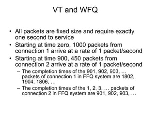
- 89. VT and WFQ All packets are fixed size and require exactly one second to service Starting at time zero, 1000 packets from connection 1 arrive at a rate of 1 packet/second Starting at time 900, 450 packets from connection 2 arrive at a rate of 1 packet/second The completion times of the 901, 902, 903, … packets of connection 1 in FFQ system are 1802, 1904, 1806, … The completion times of the 1, 2, 3, … packets of connection 2 in FFQ system are 901, 902, 903, …
- 90. Plan RR WRR VT WFQ WFFQ DRR DDRR A Downlink Scheduling
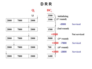
- 91. D R R Each connection is assigned a state variable called the DC (Deficit Counter). At the start of each round, DC i of queue i is incremented by a specific service share (quantum) If the length of the head of the line packet, L i , is less than or equal to DC i, , the scheduler allows the i th queue to send a packet. Once the transmission is completed DC i is decremented by L i .
- 92. D R R Q i DC i 3500 3500 2800 7800 2000 1500 5000 700 1400 2800 7800 2000 2800 7800 2000 2800 7800 2000 2800 7800 2000 initializing ( 1 st round) Serviced Not serviced Serviced Serviced (3 rd round) (4 th round) +3500 +3500 ( 2nd round) +3500 -2000 -7800 -2800 Li
- 93. Plan RR WRR VT WFQ WFFQ DRR DDRR A Downlink Scheduling
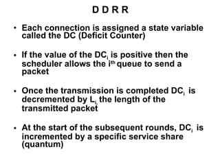
- 94. D D R R Each connection is assigned a state variable called the DC (Deficit Counter) If the value of the DC i is positive then the scheduler allows the i th queue to send a packet Once the transmission is completed DC i is decremented by L i , the length of the transmitted packet At the start of the subsequent rounds, DC i is incremented by a specific service share (quantum)
- 95. D D R R Q i DC i 3500 3500 2800 7800 2000 1500 -6300 -2800 700 -2100 2800 7800 2000 2800 7800 2000 2800 7800 2000 2800 7800 2000 2800 7800 2000 initializing (1 st round) Serviced Serviced Not serviced (2 nd round) Not serviced (3 rd round) Serviced -2000 -7800 -2800 +3500 +3500 +3500 +3500
- 96. III Downlink/Uplink Scheduling Plan A Downlink Scheduling B Uplink Scheduling
- 97. B Uplink Scheduling Uplink scheduling : Responsible for the efficient and fair allocation of the resources (time slots) in the uplink direction Uplink carrier : Reserved slots contention slots (random access slots) The standard scheduling algorithms can be used
- 98. Bibliography http://www.opalsoft.net/qos/WhyQos-2424.htm http://www.math.tau.ac.il/~alx/courses/notes/Icc8_2.ppt http://www.it.uu.se/edu/course/homepage/datakom/civinght04/schema/sliding_window.pps