IPAC2018, Vancouver, BC, Canada
JACoW Publishing
doi:10.18429/JACoW-IPAC2018-THPMK002
THE PRE-INJECTOR DESIGN FOR THE MAX IV SXL
J. Andersson∗ , M. Kotur, D. Kumbaro, F. Lindau, E. Mansten, D. Olsson, L. Roslund, S. Thorin
MAX IV Laboratory, Lund University, Lund, Sweden
Abstract
In this paper we present the current status of the design
for the pre-injector (photo-cathode gun, solenoid and first
linac) for the SXL [1] project at MAX IV. The SXL project
requires a higher repetition rate and since improved beam
quality compared to what the current photo-cathode gun
can operate at is needed, a new photo-cathode gun will be
manufactured. We briefly describe the components of the
pre-injector, followed by the design of the new photo-cathode
gun. The design is similar to the old gun but with a new RF
cavity using elliptical irises and racetrack profile main cell.
The current parameters for the next gun to be manufactured
are discussed, and some simulations and expected beam
quality from the injector are shown.
INTRODUCTION
The MAX IV SXL project is currently ongoing with
the goal of investigating and designing a Soft X-Ray Laser
source at the end of the MAX IV linac in Lund, Sweden.
The MAX IV linac is a normal conducting S-band linac,
with two different electron sources. One thermionic RF gun
used for injection to storage rings, and one photo-cathode
RF gun for production of beams for the Short Pulse Facility (SPF) [2]. The currently installed photo-cathode gun is
a 1.6 cell gun based on the BNL/SLAC type adapted for
2.9985 GHz, and results from the initial commissioning can
be found in [3], where a beam emittance in the order of 1.6
mm mrad was measured. The available repetition rate with
the currently installed gun is too low for full operations of
the SPF. At the same time, the beam quality needs to be
improved to efficiently drive a FEL and in combination, this
requires a new photo-cathode gun and a revisit of the design
of the pre-injector.
The pre-injector is considered to be the photo-cathode gun,
emittance compensating solenoid and first linac structure as
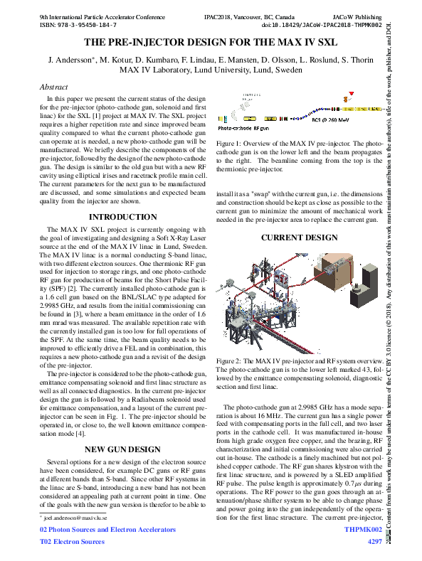
well as all connected diagnostics. In the current pre-injector
design the gun is followed by a Radiabeam solenoid used
for emittance compensation, and a layout of the current preinjector can be seen in Fig. 1. The pre-injector should be
operated in, or close to, the well known emittance compensation mode [4].
NEW GUN DESIGN
Several options for a new design of the electron source
have been considered, for example DC guns or RF guns
at different bands than S-band. Since other RF systems in
the linac are S-band, introducing a new band has not been
considered an appealing path at current point in time. One
of the goals with the new gun version is therefor to be able to
∗
joel.andersson@maxiv.lu.se
02 Photon Sources and Electron Accelerators
T02 Electron Sources
Figure 1: Overview of the MAX IV pre-injector. The photocathode gun is on the lower left and the beam propagates
to the right. The beamline coming from the top is the
thermionic pre-injector.
install it as a "swap" with the current gun, i.e. the dimensions
and construction should be kept as close as possible to the
current gun to minimize the amount of mechanical work
needed in the pre-injector area to replace the current gun.
CURRENT DESIGN
Figure 2: The MAX IV pre-injector and RF system overview.
The photo-cathode gun is to the lower left marked 43, followed by the emittance compensating solenoid, diagnostic
section and first linac.
The photo-cathode gun at 2.9985 GHz has a mode separation is about 16 MHz. The current gun has a single power
feed with compensating ports in the full cell, and two laser
ports in the cathode cell. It was manufactured in-house
from high grade oxygen free copper, and the brazing, RF
characterization and initial commissioning were also carried
out in-house. The cathode is a finely machined but not polished copper cathode. The RF gun shares klystron with the
first linac structure, and is powered by a SLED amplified
RF pulse. The pulse length is approximately 0.7µs during
operations. The RF power to the gun goes through an attenuation/phase shifter system to be able to change phase
and power going into the gun independently of the operation for the first linac structure. The current pre-injector,
THPMK002
4297
Content from this work may be used under the terms of the CC BY 3.0 licence (© 2018). Any distribution of this work must maintain attribution to the author(s), title of the work, publisher, and DOI.
9th International Particle Accelerator Conference
ISBN: 978-3-95450-184-7
�Content from this work may be used under the terms of the CC BY 3.0 licence (© 2018). Any distribution of this work must maintain attribution to the author(s), title of the work, publisher, and DOI.
9th International Particle Accelerator Conference
ISBN: 978-3-95450-184-7
IPAC2018, Vancouver, BC, Canada
JACoW Publishing
doi:10.18429/JACoW-IPAC2018-THPMK002
other side of the cavity, and in combination with a race-track
profile as discussed in [6], it should be possible to keep the
multipole components at an acceptable limit. The exterior
of the new gun can be seen in Fig. 3 and the RF cavity as
simulated in SUPERFISH [7] can be seen in Fig. 4.
Figure 3: The exterior of the new gun design with attached
vacuum pumps.
including the RF systems, can be seen in Fig. 2. The gun
is followed by an emittance compensation solenoid which
is placed as close to the gun as mechanically possible, and
the distance between the cathode and the entrance to the
first linac structure is 1.5 m. There is room to change this
distance if needed but it requires major mechanical reconstruction. The solenoid contains PCB’s for normal and skew
quadrupole field compensation, but these have not yet been
implemented. Following the solenoid is a laser chamber that
allows the laser beam to be sent in close to on axis towards
the cathode, and this chamber also contains a pepperpot and
a YAG screen for diagnostics.
As can be seen from the figures, the photo-cathode
pre-injector intersects with the thermionic pre-injector
used for ring injections. There is an energy filter and two
quadrupole magnets that are used during injections with
the thermionic electron source, and so far there has been
no significant indications that hysteresis causes issues
with the photoinjector beam. During commissioning and
subsequent experiments it has been possible to reach a
beam quality of just below 1 mm mrad with a charge of
100 pC [5]. Since the cathode is non-polished it is believed
that this is a substantial contribution to the emittance,
and normal operating emittance with around 2 mm diameter laser spot size is typically 2 mm mrad for 100 pC charge.
Based on the requirements for the repetition rate and beam
quality, combined with the progress on photo-cathode RF
gun designs, a new design for the photo-cathode gun is being
developed. There will be no significantly new features in
the design that has not already been implemented in other
gun designs, it is rather a combination of the most attractive
features for the requirements at MAX IV. The design has
been based on a 1.6 cell structure similar to the well known
one from BNL/SLAC type guns. A 2.6 cell structure has also
been considered, but is at the current time not investigated
further.
The gun will feature elliptical irises to decrease the surface electrical field, thus making it possible to go to higher
gradients while minimizing RF breakdowns. The design
will use a one sided power feed through an z coupling slot
on the main cavity to be able to easily connect it to current
systems. There will be a symmetric z coupling slot at the
THPMK002
4298
The dimensions of the irises have been changed to increase the mode separation between the pi and 0 mode, while
keeping the field amplitudes equal in the two cells. In the
currently installed gun some mode beating is seen, the effect
of it is being studied, but the mode separation is increased
to 40 MHz in the new design to be able to power the structure with short pulses from the SLED without significant
zero-mode excitation.
Figure 4: Simulation results showing electric field contour
lines and direction from Superfish for the new RF gun cavity
design.
The cooling system using water is being designed for
operations at 100 Hz with a maximum field amplitude
of 130 MV/m, and heat load is being simulated with
COMSOL and ANSYS. The projected field amplitude
during operations will however be lower, in the range of 110
- 120 MV/m. There is also a fluid circuit designed on the
back of the cathode both for cooling but possibly also to be
able to heat up the cathode in-situ.
The structure will be manufactured in high grade low
oxygen copper and will be manufactured in house. The
current technique to combine the structure is a "heat
joint", where temperature expansion will be used. In the
initial trials with this technique it has been able to keep
the temperature far from the point where the mechanical
structure of copper changes. Previous experience elsewhere
seems to indicate that conditioning is faster and less
breakdowns occur if the structure has not been heated to
high temperatures. As we are trying to keep avoid brazing
for this reason, the alternative idea is to implement a
clamping process as in [8]. However, the mechanical design
is done in such a way that brazing is possible even after
joining if required. RF measurements will be made both
with the bead and needle pull technique to measure the
electric field distributions in the structure.
02 Photon Sources and Electron Accelerators
T02 Electron Sources
�IPAC2018, Vancouver, BC, Canada
JACoW Publishing
doi:10.18429/JACoW-IPAC2018-THPMK002
BEAM SIMULATIONS
The electric field profile in the new design of the gun
will have equal amplitudes in the two cells, and the field
profile is very similar o the one in the current gun. There
are no major changes to the simple beam dynamics expected
and the pre-injector will be operated as close to the emittance compensating work point as possible. Simulations
are made using ASTRA [9] and parallelized ASTRA [10]
using the resources at LUNARC (The center for scientific
and technical computing at Lund University). 1 M particles
and a radially symmetric space charge grid where used, and
the intrinsic emittance is estimated to 0.55 mm mrad/mm.
In the pre-injector designs a 1 mm diameter laser beam is
used, the intrinsic emittance is 0.17 mm mrad, and the laser
beam is longitudinal top hat like with a length of 6 ps with
around 1 ps rise/fall time. The field in the gun is 120 MV/m,
the laser is injected at a phase of 35 degrees and the beam
charge is 100 pC. Figure 5 shows the spot size and emittance
evolution and Fig. 6 shows the charge distribution and the
slice emittance. The final emittance is 0.23 mm mrad, at a
beam energy of 104 MeV and 60 keV energy spread. The
current working point is not perfect with respect to emittance compensation (the Ferrario working point). As can
be seen from Fig. 5 the beam enters the linac (at 1.5 m)
just after the first emittance oscillation minimum instead
of the following maximum, however operating the injector
with the current settings give better emittance than operating
closer to the Ferrario working point. Further investigations
are ongoing to fully understand the causes for this, and to
possibly improve the emittance further.
Figure 6: ASTRA simulation results showing the slice emittance and the charge distribution, the rms beam length is 0.5
mm.
commissioned and tested in the MAX IV gun test stand [11].
The new design will support stable operations at 100 Hz
with at least a maximum field amplitude of 120 MV/m.
REFERENCES
[1] S. Werin et al., "The Soft X-Ray laser project at MAX IV",
in Proc. IPAC’17, pp. 2760–2762.
[2] S. Werin et al., "Short pulse facility for MAX-Lab", Nucl.
Instr. Meth.A, vol. 601, pp. 98–107, 2009.
[3] J. Andersson et al., "Initial comissioning results of the MAX
IV injector", in Proc. FEL’15, pp. 448–451.
[4] L. Serafini, J. B. Rosenzweig, "Envelope analysis of intense
relativistic quasilaminar beams in rf photoinjectors: A theory of emittance compensation", Phys. Rev. E 55, 7565, 1997.
[5] J. Andersson et al., "Emittance improvements in the MAX
IV photocathode injector”, in Proc. IPAC’17, pp. 1533 - 1536.
[6] L. Xiao et al., "Dual feed RF gun design for the LCLS”, in
Proc. PAC’05, pp. 3432–3434.
Figure 5: ASTRA simulation results showing the emittance
(solid) and spot size (dashed) evolution up until the end of
the first linac.
[7] K. Halbach et al., "SUPERFISH - A computer program for
evaluation of RF cavities with cylindrical symmetry”, 1976.
[8] D. Alesini et al., "High power test results of the eli-np
s-band gun fabricated with the new clamping technology
without brazing", in Proc. IPAC’17, pp. 3662–3665.
SUMMARY AND FUTURE
In this paper we have shortly presented the current status
of the design for a new photo-cathode gun and pre-injector at
MAX IV. The ideas for the new gun design were discussed,
and some basic simulation results with expected beam quality from the pre-injector were shown. The gun design is
currently ongoing and should be finalized during Q2 2018
and manufacturing of the structure should start during the
autumn of 2018. Once the gun is manufactured it will be
02 Photon Sources and Electron Accelerators
T02 Electron Sources
[9] K. Floettmann, "ASTRA - A space charge tracking
algorithm, DESY", 2011.
[10] Parallel ASTRA, http://tesla.desy.de/~meykopff/.
[11] J. Andersson et al., "The new MAX IV gun test stand", in
Proc. IPAC’17, pp. 1537–1540.
THPMK002
4299
Content from this work may be used under the terms of the CC BY 3.0 licence (© 2018). Any distribution of this work must maintain attribution to the author(s), title of the work, publisher, and DOI.
9th International Particle Accelerator Conference
ISBN: 978-3-95450-184-7
�
 Erik Mansten