Advanced Robotics 24 (2010) 1679–1694
brill.nl/ar
Full paper
Laparoscopic Surgical Robot for Remote In Vivo Training
Brian F. Allen a,∗ , Brett Jordan b , William Pannell b , Catherine Lewis c ,
Erik Dutson c and Petros Faloutsos a
a
Department of Computer Science, University of California at Los Angeles, 4732 Boelter Hall,
Los Angeles, CA 90095, USA
b
Department of Mechanical Engineering, University of California at Los Angeles,
48-121 Engineering IV, 420 Westwood Plaza, Los Angeles, CA 90095, USA
c
Department of Surgery, University of California at Los Angeles, 200 UCLA Medical Plaza,
Los Angeles, CA 90095, USA
Received 14 July 2009; accepted 21 December 2009
Abstract
The Laparobot is a tele-operated robot designed specifically for training surgeons in advanced laparoscopic
techniques. The Laparobot allows a student to practice surgery on a remotely located animal. The system
uses standard laparoscopic tools for both the student’s control interface and for performing the in vivo
surgery, thereby providing a realistic training platform for non-robotic laparoscopic surgery. By allowing
students to practice surgery remotely, animal models become more accessible and less expensive, and can
replace learning on human patients. The Laparobot addresses problems inherent in designing a low-cost,
tele-operated robot.
Koninklijke Brill NV, Leiden and The Robotics Society of Japan, 2010
Keywords
Laparoscopic surgery, tele-operation, animal model, surgical training
1. Introduction
Minimally invasive surgery (MIS) provides significant benefits to patients, including shorter hospital stays, smaller scars and faster healing. However, MIS procedures can be significantly more complex than their open counterparts and so require
additional training. Studies of laparoscopic surgery learning show that the rate of
technical complications only stabilizes after 80–100 procedures [1, 2] and decreases
with experience by as much as 50% [3].
*
To whom correspondence should be addressed. E-mail: vector@cs.ucla.edu
Koninklijke Brill NV, Leiden and The Robotics Society of Japan, 2010
DOI:10.1163/016918610X522513
�1680
B. F. Allen et al. / Advanced Robotics 24 (2010) 1679–1694
The training and assessment problem for laparoscopic surgery is both acute and
well-recognized [4]. Previous studies have shown that low-level, psychomotor skills
can be taught using simple, inanimate training systems (box trainers), such as those
from the common Fundamentals of Laparoscopic Surgery program [5]. To train
higher-level skills, simplistic models may be insufficient [6]. Two main approaches
for the instruction of higher-level skills are virtual reality (VR) simulators and in
vivo animal models. While VR simulators show great promise, and may someday
provide sufficient realism to make the use of living tissue in training redundant,
accurate and real-time simulation of the complex deformations, piercing, tearing
and cutting of organic tissue remains an unsolved problem [7].
The porcine model was recognized early-on as effective for the training of a variety of laparoscopic procedures [8–10]. Although the porcine model is a powerful
pedagogical tool, there remain barriers to its widespread use in surgical training.
While ethical questions about the use of animals for training are not to be ignored,
generally the most limiting impediment to the use of animal models is the expense
and difficulty of maintaining a veterinary facility [11]. Such expense is compounded
by the need to maintain close proximity to a medical school. While possible for
large and well-endowed research institutions, schools in urban areas or those with
smaller numbers of students are often unable to provide animal models for training [12]. We propose a tele-operated surgical robot to alleviate this problem. Our
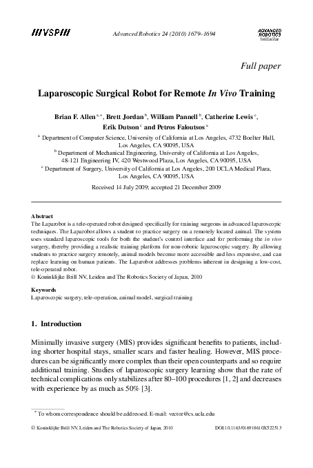
system, the Laparobot (Fig. 1), capitalizes on the wide availability of Internet access for data communication to allow students of surgery an inexpensive means to
access animals arbitrarily distant. Using our system, schools without local access
to animal facilities can partner with institutions that do have such facilities to offer
training with porcine models.
Our approach builds on a long history of robotic teleoperation for laparoscopic
surgery [13–17]. However, to date, little attention has focused on the potential for
tele-operated training and the corresponding need for low-cost operating stations.
Existing commercial systems for non-remote robotic surgery such as the da Vinci
(a)
(b)
Figure 1. A surgeon practices a common laparoscopic training task (peg transfer) by remote operation
of the robot. (a) The control station allows a surgeon to tele-operate using standard laparoscopic
instruments in a conventional arrangement. (b) The robot is remotely operated to perform the training
task.
�B. F. Allen et al. / Advanced Robotics 24 (2010) 1679–1694
1681
system (Intuitive Surgical, Mountain View, CA, USA), are prohibitively expensive
for teaching purposes. Clearly, a requirement to operate on humans, with the safeguards, tolerances, and US Food and Drug Administration-approval implied, incurs
significant design and engineering constraints to ensure the safety of the patient
and the reliability of the system. The goals of this project differ. Specifically, the
primary driver is to provide a system with low deployment cost and overhead, sufficient ease of use, and a method of operation that precisely mirrors the motions used
in laparoscopic surgery. That is, the design of this system allows remote surgery
using existing, standard laparoscopic instruments and established laparoscopic procedures. Most previous robotic surgery systems designed for tele-operation, such
as the BlueDRAGON [18], da Vinci [19] and Zeus [16], attempt to improve the
precision, dexterity or stability of the surgeon’s motions [20]. Although such improvements are useful for the primary goal of conducting surgery, they severely
limit the utility as a training platform for conventional, non-robotic laparoscopic
surgery. By using standard laparoscopic instruments as both the robotic manipulators and control interfaces, our approach attempts to remain transparent; to be
neither beneficial to the surgeon nor a hinderance.
2. System Operation and Overview
The Laparobot functions as a human-in-the-loop tele-operated robot and is composed of two similar stations, the control station (Fig. 1a) and the surgical robot (Fig. 1b). Figure 2 illustrates the interactions of the major components. A small
set of sensors tracks motions of the laparoscopic instruments manipulated by the
surgeon at the control station. These motions are encoded and sent over an Internet connection to the surgical robot. The robot receives the motions as commands
Figure 2. Flow of interaction and data through the system. The surgeon uses the system to operate on
a living animal specimen at a remote location.
�1682
B. F. Allen et al. / Advanced Robotics 24 (2010) 1679–1694
and actuates its attached laparoscopic instruments to perform identically. There is
a consistent one-to-one mapping of motion between the surgeon’s control station
instruments’ motions and the surgical robot instruments’ motions.
3. Surgical Robot
The surgical robot is designed to manipulate standard laparoscopic surgical tools
that have a shaft diameter of 5 mm and shaft length of approximately 36 cm.
Each instrument has 5 controlled d.o.f. driven by three actuating mechanisms: positional control using a parallel mechanism (3 d.o.f.), servo-controlled axial rotation
(1 d.o.f.), and servo-controlled grasping (1 d.o.f.).
3.1. Positional Control using a Parallel Mechanism
The position of each laparoscopic instrument is controlled using three DC motors
(Maxon 268212) interconnected by a parallel linkage based on the Delta robot [21].
The delta mechanism rigidly affixes the positioning motors to the stationary base
platform. This provides two main benefits over single-parallelogram designs, such
as used in the da Vinci robot [19] and others: (i) the mass of the linkages is significantly reduced, since no positioning motors need to be mounted on actuated
linkages, and (ii) heavier and larger motors can be used for positioning, if needed,
without significant alteration to the design.
However, the tight coupling of the d.o.f. in the delta mechanism complicates the
control of the robot. For example, to move the end-effector along a linear trajectory,
the three motors must apply a nonlinear and changing combination of torques. The
approach used by the robot is an independent PID controller for each d.o.f. That is,
torque τ applied at each motor at time t is calculated as:
�� t
�
dθ
τ (t) = kp (θ̂ − θ ) + ki S
(1)
θ̂(x) − θ (x) dx + kd ,
dt
t′
where kp , ki and kd are constants, θ̂ is the target position, t ′ is the time θ̂ was last
changed and x is a variable of integration. S(·) is a saturation function limiting the
wind-up of the integral term to the range [−l, l]. This function is useful in cases
where the target position is unattainable, such as when blocked by collision. By
limiting the range of the integral term, eventual recovery is always possible. The
closed-loop control is updated at a constant rate of approximately 2000 Hz.
3.1.1. Inverse Kinematics
The PID control of (1) is applied in terms of the shoulder joint θi for the purpose of
determining motor torques. Control commands received by the robot over the network specify target positions in world coordinates. Inverse kinematics maps from
target position (x, y, z) to target motor angles (θ1 , θ2 , θ2 ). Each arm of the robot is
considered separately, as the motor angles are fully and independently determined
by a given target position. The relation determining this inverse kinematic mapping
�B. F. Allen et al. / Advanced Robotics 24 (2010) 1679–1694
(a)
1683
(b)
Figure 3. A parallel mechanism driven by three motors is used to control the position of the laparoscopic instrument. (a) Schematic view of the actuators and linkages needed to control position of one
laparoscopic instrument. (b) Diagram of the dimensions of the parallel mechanism.
is:
θi =
π
− tan−1 (xi /yi )
2
xi
� L2 + (
)2 − (ρ cos(sin−1 (zi /ρ)))2 �
sin(tan−1 (xi /yi ))
−1
− cos
,
2L sin(tan−1xi(x /y ))
i
(2)
i
where L and ρ are the lengths of the lower and upper arm, respectively, and θ is the
motor angle. The nomenclature is shown in Fig. 3b. The subscript i indicates the
arm (1, 2 or 3) considered.
3.1.2. Data-Driven Compensation of Static and Quasi-Static Forces
As described in Section 1, an important practical goal of the system is to support
the modularity of standard commercial instruments by allowing the use of new
instruments. Previously unseen instruments can be used with the system, but require
an active measurement procedure to determine their mass and interaction properties.
In particular, the two main external forces being applied to the instrument are
gravity and the deformation of the abdominal wall at the trocar entry point. Although in this report the trocar used has very little deformation and low friction, in
vivo the trocar deforms the abdominal wall with each change in position. To avoid
the difficult modeling problem required to predict the resulting forces on the trocar
from the specimen, our system measures the actual forces, stores the data in a timeefficient data structure and then alters the control parameters based on interpolated
results of the run-time look-up.
�1684
B. F. Allen et al. / Advanced Robotics 24 (2010) 1679–1694
Figure 4. Visualization of the gravity-compensation torques applied at 1200 points in the workspace.
An illustrative subset of the data gathered in this process for the needle-driver
instrument is represented as a vector field in Fig. 4. The base position of each vector
is the target tool-tip position in world space. The components of each vector are the
torque of each motor (τ1 , τ2 , τ3 ) for that base target position. The vector’s length
is proportional to its length and thus denotes the total torque applied. Note that the
direction and magnitude of the vector are in units of torque, while the location of the
base of the vector is the target position (x, y, z). Next, we describe the measurement
procedure and follow with a detailed explanation of the run-time interpolation.
The active measurement procedure is fully automated in software and requires no
operator intervention. First, the magnetic position sensor described in Section 4.1
is affixed to the gimbal plate of the robot, in a manner identical to that described for
the control interface. A uniform grid of positions is then defined to cover the full
workspace. Each grid location is targeted by the robot. Once the target is reached
and the measured position is verified by the magnetic position sensor, the torques
required by each motor are recorded along with the position. The target is then
moved to the next grid location.
In order to minimize the time required by the procedure, target positions are
chosen so that between two subsequent positions only one motor is required to
change angle and only moves by one grid position. This allows full coverage of
the workspace with the minimum possible total change in motor angles. As an illustrative example, consider a three-position, three-value pattern: (0, 0, 0) (1, 0, 0)
(2, 0, 0) (2, 1, 0) (1, 1, 0) (0, 1, 0) . . . . Such patterns are multiple-value n-ary grey
codes [22]—a more complex form of the patterns used in optical encoders. While
not strictly necessary, using such a pattern for active measurement significantly decreases the time and energy required for accurate torque measurements.
The resulting torque and position measurements are then stored in a threedimensional (3-D) k–d tree data structure [23]. At runtime, the k–d tree allows
rapid retrieval of the torque measurements previously made in the neighborhood
�B. F. Allen et al. / Advanced Robotics 24 (2010) 1679–1694
1685
of a given target position. These previous measurements are then used to estimate
the motor torque τ̂ needed at the target position. Specifically, the k nearest points
(p1 , . . . , pk ) to the target position p̂ are found by searching the k–d tree, an operation that takes O(n1−1/3 + k), where n is the total number of measurements in
the data structure. Once the nearby points are identified, the corresponding sample
torques (τ 1 , . . . , τ k ) are retrieved, where the superscript indicates the corresponding position. Thus, the torque estimate τ̂ for position p̂ is:
τ̂ =
k
�
τi
i=1
k
|pi − p̂|
�k
j
j =1 |p − p̂|
.
(3)
To make use of the estimated torque τ̂ in conjunction with the PID controller, the
integral term in (1) is instantaneously set to kτ̂i with each new position target. That
is, the integral term is artificially set to the value that, if the system were at the target
position with zero velocity, would maintain equilibrium by balancing the expected
net forces with the PID-computed torque. After the integral term is set, it is allowed
to accumulate as usual. The key benefit to this approach is that it gives the system
the ability to compensate for quasi-static forces arising from the deformation of the
animal’s abdominal wall. Note that PID control without this compensation would
work, but would take significantly longer to reach equilibrium at the set-point.
3.2. Servo Control of Axial Rotation and Grasping
Axial rotation is controlled by a small servo (Futaba, Chiba, Japan) fixed beneath
the gimbal plate of the delta mechanism. The gimbal plate does not rotate with the
instrument, providing a rotational reference that otherwise travels with the motion
of the instrument. The instrument is linked to the servo by a small gear fixed to
the instrument shaft using a removable locking screw, allowing 180◦ of rotation.
This range approximately matches the full comfortable range of motion used by
the surgeons, although care is needed to ensure the range of motion of the servo is
aligned to the instrument’s proper orientation prior to use. The servo is able to drive
the instrument through the full range of motion in 0.3 s, which was found sufficient
for the relatively low angular velocities used in training. Figure 5 shows the axial
mount.
The grasping servo motor (Futaba) is mounted in the handle of the instrument,
with the servo acting on a small lever-arm to open and close the tool grasper. The
servo motor has an operating range of 90◦ , which is translated by a small lever arm
to control the instrument’s full range of grasping. The servo drives the grasper from
fully closed to fully open in 0.2 s, with approximately 1.7 kg cm of torque.
4. Control Station
The control station, shown in Fig. 6, provides a working interface very similar
to a conventional box trainer. An aluminum base-plate holds two laparoscopic
instruments at a common operating angle and a non-actuated parallel kinematic
�1686
B. F. Allen et al. / Advanced Robotics 24 (2010) 1679–1694
Figure 5. The axial servo is mounted on a platform attached to the center of the gimbal plate.
Figure 6. Control station.
linkage passively restricts the motions of the instruments to the working space of
the system, and thus provides a rudimentary form of proprioceptive feedback to the
surgeon. The instructor interacts with the instruments as if performing a standard
laparoscopic surgery while receiving visual feedback from the video monitor. By
design, the ergonomic experience when controlling the robot is as close as possible
to the experience of performing a procedure in the operating room. In particular,
the handles are based on standard laparoscopic instruments (Karl Storz EndoscopyAmerica, Culver City, CA, USA). The instruments are modified to contain small,
light-weight (4 g) linear potentiometers (Model 9605; BEI Duncan Electronics,
Irvine, CA, USA) in the handle. The potentiometer measures the grasper position
(open to closed). This position is sent via the BlueTooth wireless protocol to the
nearby control computer, which in turn sends the position as a control command to
the robot, as described in Section 5. In addition, the axial rotation of the instrument
is measured by an attached optical encoder, connected to the control computer by
USB.
4.1. Spatial Tracking
The instructor interfaces with the system by moving standard laparoscopic instruments. To track these motions, a small magnetic sensor (microBird; Ascension,
Burlington, VT, USA) was rigidly attached to the gimbal plate of the kinematic
�B. F. Allen et al. / Advanced Robotics 24 (2010) 1679–1694
1687
linkage (see Section 3.2). The sensor was mounted to a small plate made of highgrade acrylic resin with a cut groove of the width of the sensor, allowing the sensor
to be removed and replaced in precisely the same location relative to the gimbal
plate. The sensors are small (1.3 mm) and lightweight (0.2 g) with a nominal accuracy of 0.48 mm. When stationary, the sensors report the 3-D location with a
precision measured to 0.13 mm of root mean square (r.m.s.) error. This configuration was originally designed for the passive collection of motion data during
training exercises [24].
5. Communication of Control Signals over the Internet
The measured state of the control station instruments is sent over a standard packetswitched Internet connection to the robot. Each of the three separate sensory systems is independent and each uses a separate packet stream as control signal. Three
control signals are sent as three separate UDP packet streams, each on a unique and
pre-assigned port. The UDP itself has neither error checking nor error correction.
The computer at the control station computes a 1-byte checksum on each outgoing
packet to allow the receiving robot to detect corrupted packets. Corrupted, dropped
and out-of-order packets are ignored. Order is determined by a millisecond timestamp in each data packet. UDP is selected over the more complex TCP to reduce
latency and to avoid protocol-required automatic retransmission of lost or corrupted
packets. Under ideal conditions the latency of both protocols is roughly equivalent
for this application; however, when establishing the connection or in the case of
packet loss or corruption, UDP has lower latency by up to twice the round-trip
time [25].
A packet is sent as soon as a sensor detects a state-change, unless a packet was
sent on that channel within the last 0.0167 s. In that case, a timer is set to 0.0167 s
after the last-sent packet. On expiration of the timer, the most recent available sensor
reading is encoded in a packet and sent. In this way, across all three control streams,
at most 3 × (1/0.0167) = 180 UDP packets/s will be sent across the network per
instrument. Using three separate streams allows three separate timers, reducing the
latency, since packets are sent on detected changes in state. The position control
packets carry three positions of 4 bytes each, plus the common 4-byte timestamp.
Both axial and grasper control packets hold a single 4-byte value in addition to
the timestamp. The UDP format requires 8 bytes and IPv4 an additional 20. Using
the standard configuration with two instruments controlled, the maximum data rate
used is 13920 bytes/s (or less than 140 kb/s). Network delays beyond transmission
time are not modeled and may result in unexpected lag to the system. However, in
practice, the risk of such delays can be mitigated by using dedicated transmission
lines.
5.1. Laparoscopic Video Feedback
Whereas the control signals travel from the control station to the robot, a live video
stream is captured at the robot and sent to the control station. The video camera
�1688
B. F. Allen et al. / Advanced Robotics 24 (2010) 1679–1694
is a Storz Endoskope (Karl Storz Endoscopy-America) providing a resolution of
768 × 494 pixels. The video signal is encoded and transmitted to the control station.
When a closed-circuit video connection is not available, the video is encoded to
H.264 (MPEG-4 Part 10) at 24 frames/s with an encoding latency of approximately
30 ms. The resulting video stream requires approximately 2 Mb/s.
6. Results
To objectively evaluate the performance of the system, the positional and tracking
accuracies are measured. While there are a number of surgical systems designed for
human operations, to our knowledge, no tele-operated in vivo training robots have
been described previously.
6.1. Measured Accuracy
Accuracy is paramount to successful tele-operational surgery. Positional error can
occur in both the positional sensing and the robotic control. Sensory accuracy is
described and quantified in Section 4. In this section, measurement of the accuracy
of the robot and control system is reported.
As described in Section 4.1, the observed r.m.s. error in spatial tracking was
0.13 mm. For validation experiments, a second magnetic sensor was affixed to the
distal tip of the instrument. This distal sensor is necessarily less precise due to
magnetic field interference caused by the mounting hardware and motors in the
vicinity of the magnetic emitter and the sensor. The observed r.m.s. error for this
distal sensor was 0.25 mm, approximately twice the observed error in the handle
sensor.
To measure tracking accuracy, a trajectory is generated analytically and sampled
at 15 Hz. Each sample is sent over the network as a stream of control packets in a
manner indistinguishable from motions generated by the surgeon’s control console.
During testing, a magnetic sensor, equivalent to those used by the surgeon control console and described in Section 4.1, is rigidly fastened to the tool-tip of the
instrument. This setup allows precise tracking of the instrument in the same coordinate system that motion commands are specified. Before each test, the position of
the instrument is calibrated to eliminate static positional error.
Two types of measurements were collected—the motion trajectory resulting from
a discrete change in the target position (point-to-point) and the error in position
while dynamically tracking a linear trajectory. Figure 7 shows the (X, Y , Z) position of the tool-tip in the world coordinate frame. The target position is changed
every 10 s to a point 22.1 mm away. The overshoot in position ranges between a
maximum of 0.89 mm to less than the r.m.s. error of the position sensor (0.13 mm).
The noise in the position between changes in position is due to noise in the position
sensor.
The second type of collected measurement is linear tracking. Note that tracking
a world-space line requires motion from all three motors and is a test of motor coordination, rather than a single d.o.f. Figure 8 reports the actual trajectory followed
�B. F. Allen et al. / Advanced Robotics 24 (2010) 1679–1694
1689
Figure 7. Trajectory in X, Y and Z planes while targeting a set-point that changes position by 22.1 mm
every 10 s.
(a)
(b)
Figure 8. Sampled error while tracking of a linear trajectory at 10.2 mm/c. (a) Target (solid black
line) and actual positions during tracking. Color indicates the amount of error for that sample, with
red points being the locations of highest error. (b) Absolute error as a function of X position (r.m.s. of
the error indicated by the bold dashed horizontal line).
by the tool-tip during a 10.2 mm/s linear motion and the observed error from target trajectory during that motion. The r.m.s. of the error is shown as a horizontal
dashed line, along with a grey band indicating the nominal precision of the position
measurement.
The target trajectory of Fig. 8 has a velocity of 10.2 mm/s. This was experimentally found to be the mean velocity when expert surgeons performed a basic training
task (peg transfer). Other tested tasks, such as passing a rope and capping a needle,
had lower mean velocities (see Ref. [24] for details on collection procedures). As
the velocity of the target position increases, the mean observed error also increases.
�1690
B. F. Allen et al. / Advanced Robotics 24 (2010) 1679–1694
Figure 9. Linear trajectory error as a function of target velocity. The shaded band indicates measured
mean velocities during training tasks.
This relationship is shown in Fig. 9. The shaded vertical line shows the range of
mean velocities observed during expert performance of training tasks.
6.2. Workspace
The workspace of the robot is the region of space reachable by the tool-tip of the laparoscopic instrument. The workspace must be sufficiently large to allow unfettered
motion within the abdominal cavity of the animal. A recent study [26] characterized the workspace used across seven surgical tasks in a porcine model. This report
described a workspace of a solid circular cone with a vertex angle of 60◦ would
contain 95% of tool-tip motion for the porcine model. The workspace of the mechanism proposed here provides a maximum lateral range of 65◦ and a maximum
anteroposterior angle of 72◦ . This workspace has a complex shape due to the geometric complexity of the parallel mechanism. The workspace of the robot is shown
in Fig. 10.
7. Conclusion
The training of laparoscopic surgeons has been and remains an important topic of
research for nearly 20 years. It is widely recognized that animal models provide an
excellent basis for learning advanced surgical skills. Although greater use of animals for training has significant ethical questions, those questions are matched by
the significant differences in error rate and post-surgery complication rate between
new surgeons and experienced surgeons. Training based on animal models may reduce the risk associated with a surgeon’s early-career procedures. At the present
time, however, few surgeons are provided the opportunity to train using porcine
models due to the expense and remoteness of animal facilities.
Tele-robotics may provide a solution. The proposed Laparobot aims to complement the final stages of a surgeon’s education with in vivo training and thereby to
�B. F. Allen et al. / Advanced Robotics 24 (2010) 1679–1694
1691
Figure 10. Blue sample points illustrate the working space of the tool-tip.
reduce the number of complications arising during a surgeon’s first procedures. Future versions of the Laparobot will investigate the ability of tactile feedback, such as
through a pneumatic display [27], and proprioceptive feedback, obtained by adding
actuators to the control console, to improve the fidelity of the training experience.
Acknowledgements
The study was partially supported by the US Army Telemedicine and Advanced
Technologies Research Center (TATRC). We wish to thank Karl Storz EndoscopyAmerica, Intel and Autodesk for generous support through equipment and software
grants. We also wish to thank Vasile Nistor and Greg Carman for their contributions
to the mechanical design, helpful advice and discussions.
References
1. D. J. Biau, S. M. Williams, M. M. Schlup, R. S. Nizard and R. Porcher, Quantitative and individualized assessment of the learning curve using LC-CUSUM, Bri. J. Surg. 95, 925–929 (2008).
2. T. Sovik, E. T. Aasheim, J. Kristinsson, C. F. Schou, L. My Diep, A. Nesbakken and T. Mala,
Establishing laparoscopic Roux-en-Y gastric bypass: perioperative outcome and characteristics of
the learning curve, Obes. Surg. 19, 158–165 (2009).
3. P. Schauer, S. Ikramuddin, G. Hamad and W. Gourash, The learning curve for laparoscopic Rouxen-Y gastric bypass is 100 cases, Surg. Endosc. 17, 212–215 (2003).
4. R. Aggarwal, K. Moorthy and A. Darzi, Laparoscopic skills training and assessment, Bri. J. Surg.
91, 1549–1558 (2004).
5. J. H. Peters, G. M. Fried, L. L. Swanstrom, N. J. Soper, L. F. Sillin, B. Schirmer and K. Hoffman,
Development and validation of a comprehensive program of education and assessment of the basic
fundamentals of laparoscopic surgery, Surgery 135, 21–27 (2004).
6. J. U. Stolzenburg, M. C. Truss, R. Rabenalt, M. Do, T. Schwalenberg, P. F. Katsakiori, A. McNeill
and E. Liatsikos, Training in laparoscopy, EAU-EBU Update Ser. 5, 53–62 (2007).
7. S. Misra, K. T. Ramesh and A. M. Okamura, Modeling of tool-tissue interactions for computer–
based surgical simulation: a literature review, Presence 17, 463–491 (2008).
�1692
B. F. Allen et al. / Advanced Robotics 24 (2010) 1679–1694
8. W. O. Kirwan, T. K. Kaar and R. Waldron, Starting laparoscopic cholecystectomy—the pig as a
training model, Irish J. Med. Sci. 160, 243–246 (1991).
9. D. I. Watson, P. J. Treacy and J. A. R. Williams, Developing a training model for laparoscopic
common bile duct surgery, Surg. Endosc. 9, 1116–1118 (1995).
10. A. Olinger, G. Pistorius, W. Lindemann, B. Vollmar, U. Hildebrandt and M. D. Menger, Effectiveness of a hands-on training course for laparoscopic spine surgery in a porcine model, Sur. Endosc.
13, 118–122 (1999).
11. F. P. Gruber and T. Hartung, Alternatives to animal experimentation in basic research, ALTEX
Alternativen zu Tierexperimenten 21, 3–31 (2004).
12. K. E. Roberts, R. L. Bell and A. J. Duffy. Evolution of surgical skills training, World J. Gastroenterol. 12, 3219–3224 (2006).
13. J. W. Hill, P. S. Green, J. F. Jensen, Y. Gorfu and A. S. Shah, Telepresence surgery demonstration
system, in: Proc. IEEE Int. Conf. on Robotics and Automation, San Diego, CA, pp. 2302–2307,
(1994).
14. M. C. Cavusoglu, F. Tendick, M. Cohn and S. S. Sastry, A laparoscopic telesurgical workstation,
IEEE Trans. Robotics Automat. 15, 728–739 (1999).
15. A. Madhani, G. Niemeyer and J. Salisbury, The Black Falcon: a teleoperated surgical instrument
for minimally invasive surgery, in: Proc. IEEE/RSJ Int. Conf. on Intelligent Robots and Systems,
Victoria, BC, vol. 2, pp. 936–944 (1998).
16. J. Marescaux, J. Leroy, F. Rubino, M. Smith and M. Vix, Transcontinental robot-assisted remote
telesurgery: feasibility and potential applications, Ann. Surg. 235, 487–492 (2002).
17. P. Berkelman and J. Ma, The University of Hawaii teleoperated robotic surgery system, in: Proc.
IEEE/RSJ Int. Conf. on Intelligent Robots and Systems, San Diego, CA, pp. 2565–2566 (2007).
18. M. J. H. Lum, D. Trimble, J. Rosen, K. F. Ii, H. H. King, G. Sankaranarayanan, J. Dosher, R.
Leuschke, B. Martin-Anderson, M. N. Sinanan and B. Hannaford, Multidisciplinary approach
for developing a new minimally invasive surgical robotic system, in: Proc. IEEE/RAS-EMBS Int.
Conf. on Biomedical Robotics and Biomechatronics, Pisa, pp. 841–846 (2006).
19. G. S. Guthart and J. K. Salisbury, The Intuitive™ telesurgery system: overview and application,
in: Proc. IEEE Int. Conf. on Robotics and Automation, San Francisco, CA. vol. 1, pp. 618–621
(2000).
20. A. R. Lanfranco, A. E. Castellanos, J. P. Desai and W. C. Meyers, Robotic surgery: a current
perspective, Ann. Surg. 239, 14 (2004).
21. R. Clavel, Delta, a fast robot with parallel geometry, in: Proc. 18th Int. Symp. on Industrial Robots,
Lausanne, pp. 91–100 (1988).
22. P. Elias, Coding for noisy channels, IRE Conv. Rec. 3, 37–46 (1955).
23. J. H. Friedman, J. L. Bentley and R. A. Finkel, An algorithm for finding best matches in logarithmic expected time, ACM Trans. Math. Software 3, 209–226 (1977).
24. B. Allen, V. Nistor, E. Dutson, G. Carman, C. Lewis and P. Faloutsos, Support vector machines improve the accuracy of evaluation for the performance of laparoscopic training tasks, Surg. Endosc.
24, 170–178 (2010).
25. J. Postel, User datagram protocol, RFC 768, Internet Engineering Task Force (1980).
26. M. Lum, D. Trimble, J. Rosen, K. Fodero, H. King, G. Sankaranarayanan, J. Dosher, R. Leuschke,
B. Martin-Anderson, M. Sinanan and B. Hannaford, Multidisciplinary approach for developing a
new minimally invasive surgical robotic system, in: Proc. IEEE/RAS–EMBS Int. Conf. on Biomedical Robotics and Biomechatronics, Pisa, pp. 841–846 (2006).
�B. F. Allen et al. / Advanced Robotics 24 (2010) 1679–1694
1693
27. C. H. King, M. O. Culjat, M. L. Franco, J. W. Bisley, E. Dutson and W. S. Grundfest, Optimization
of a pneumatic balloon tactile display for robot-assisted surgery based on human perception, IEEE
Trans. Bio-Medical Engineering 55, 2593 (2008).
About the Authors
Brian F. Allen is pursuing his PhD at the University of California at Los Angeles where he works in both the Computer Graphics Laboratory (MAGIX) and
the Center for Advanced Surgical and Interventional Technology (CASIT). He received his BS in Computer Science from Iowa State University, in 2005. He is
interested in the characterization and artificial synthesis of human motion, and the
application of models of motion to computer animation and medicine.
Brett Jordan received the BS degree (2006) and MS degree (2008) in Mechanical
Engineering from the University of California, Los Angeles (UCLA). He worked
in the UCLA Center for Embedded Networked Sensing (CENS) and the UCLA
Center for Advanced Surgical and Interventional Technology (CASIT) while attending UCLA. There he was an influential leader of the team that designed,
developed and implemented a variety of projects ranging from environmental
sensing systems to surgical robotic systems. He is currently working for an earlystage medical device company in Los Angeles, but is still active at UCLA as a
Product Development engineer.
William Pannell is pursuing his MD at the University of California at Los Angeles (UCLA) David Geffen School of Medicine. He received his BS in Mechanical
Engineering from UCLA, in 2009, with an interest in design and manufacturing. His research interests include surgical robotics and complications from spinal
surgery.
Catherine Lewis is a fifth-year General Surgery Resident at the University of
California, Los Angeles. She received her BS in Biochemistry from the University of Arizona, in 1998, and her MD from the University of Michigan, in 2005.
She recently completed a 2-year research fellowship in the Center for Advanced
Surgical and Interventional Technology (CASIT) at the University of California,
Los Angeles during which she participated in the development of a pneumatic tactile feedback system for robotic surgery as well as a haptic-guidance system for
laparoscopic tools.
�1694
B. F. Allen et al. / Advanced Robotics 24 (2010) 1679–1694
Erik Dutson received his BS degree in 1990 from The College of William and
Mary in Williamsburg, VA, USA, where he was on the Dean’s List. He subsequently attended medical school at Eastern Virginia Medical School, receiving his
MD degree, in 1995. After completing medical school, he remained in Norfolk to
complete his general surgery residency training, which he completed with honors,
in 2000. Seeking to further his excellent clinical experience, he worked for 1 year
as a Locum Tenens surgeon, which gave him the opportunity to participate in a
variety of practices in different hospitals all over the country while helping out
communities in dire need of a well-trained general surgeon. An increasing interest in advancing surgical technologies guided him to Strasbourg, France, where he worked for 2 years as a Clinical and
Research Fellow at the European Institute for Telesurgery at the University of Louis Pasteur. During
this time, he learned a wide variety of advanced minimally invasive surgical techniques, including
bariatric procedures, from a conglomeration of world-renowned experts. He participated in robotic
surgical investigations, and helped develop and validate virtual and augmented reality applications
for surgery. As part of this experience, he participated in the training of approximately 8000 surgeons from all over the world in advanced laparoscopic procedures and worked on a day-to-day basis
with the team that performed the first-ever transatlantic tele-robotic long-distance surgical procedure.
Upon returning to the USA, he joined the newly formed Minimally Invasive Section at UCLA’s Department of Surgery, in September 2003. He is Board-Certified in Surgery and an Associate Fellow
of the American College of Surgeons. He has pending memberships in the Society of American Gastrointestinal and Endoscopic Surgeons (SAGES), the Society of Laparoendoscopic Surgeons (SLS),
and the American Society of Bariatric Surgery (ASBS). He has authored several scientific papers that
have been published or accepted for publication in peer-reviewed surgical journals. He has also spoken at several local, national, and international meetings, as well as having helped to develop CME
accreditation for web-based surgical education, and worked as a web-based editor and author of surgical texts. His clinical interests include laparoscopic bariatric surgery (Roux-en-Y gastric bypass and
adjustable banding); laparoscopic gastric, upper and lower intestinal surgery; minimally invasive hiatal, paraesophageal, inguinal, ventral and incisional herniorrhapy; laparoscopic adrenalectomy and
splenectomy; and flexible lower and upper endoscopy.
Petros Faloutsos is an Assistant Professor at the Department of Computer Science at the University of California at Los Angeles. He received his PhD degree
(2002) and his MS degree in Computer Science from the University of Toronto,
Canada, and his BE degree in Electrical Engineering from the National Technical
University of Athens, Greece. He is the Founder and Director of the Computer
Graphics Laboratory at the Department of Computer Science at UCLA. The laboratory, called MAGIX (Modeling Animation and GrafIX), performs state of the
art research in graphics virtual humans, hardware accelerators for graphics and
surgical robotics. He is also interested in computer networks and he has co-authored a highly cited
paper on the topology of the Internet. He is a Member of the Editorial Board of the journal The Visual
Computer and has served as a Program Co-Chair for the ACM SIGGRAPH/Eurographics Symposium
on Computer Animation (2005). He is a Member of the ACM and the Technical Chamber of Greece.
�
 William Pannell