Design and Implementation of Smart Billing and Automated Meter Reading
System for Utility Gas
Muhammad Faheem Khan, Ahmed Zoha and Rana Liaqat Ali
Department of Electrical Engineering, COMSATS Institute of
Information Technology, Islamabad (CIIT)-Pakistan
E-mail: faaheemkhaan@gmail.com, muhammad_fahim@comsats.edu.pk
Abstract
Billing automation systems for public utilities (e.g.
electricity, gas and water) have been widely studied
and implemented in developed countries across the
world. But in Pakistan, this technology is still on its
way to be implemented for domestic as well as for
industrial consumers. This paper explores the design,
implementation and application of billing automation
system for gas consumers in Pakistan. For low gas
consumption (domestic consumers), a prepaid meter
has been designed which needs a prepaid card to keep
the gas supply continue. Similarly for high gas
consumption (industrial consumers), the gas meter is
wirelessly connected with the regional billing office. In
this way the billing office is able to directly
communicate with the meter and records its gas
consumption reading. Along with the gas, this system
can easily be enhanced to measure the consumption of
electricity and water.
enters the meter readings in a computer to calculate the
bills. Thirdly at the end, the bills (in paper form) are
sent home to home (to gas consumers).
The above stated process is manual and prone to
defects and ultimately the consumers mentally and
financially suffer in such billing system. Therefore to
replace the manual and traditional billing techniques in
Pakistan, we designed and implemented a cost
effective, but still reliable, billing automation system
for gas provider companies. As already discussed that
analogue meters are already being used in Pakistan
therefore in our system we modified an analogue meter
and converted it into a digital gas meter. In this way the
gas provider companies would not have to completely
replace their existing setup facilities and they would be
able to replace their existing billing methods with our
automated system.
2. System Configuration
There are three major modules of this system:
1. Introduction
The Automated Meter Reading (AMR) was started
in 1962 by AT&T, but this experiment was not
successful. The modern era of AMR started in 1985;
since then different techniques have been utilized to get
better reliability and performance [9]. Therefore
currently in developed countries, many successful
AMR systems are being used to facilitate the
consumers of water, gas or electricity. However in
Pakistan, service provider companies (e.g. WAPDA,
SNGPL, WASA, etc) are still using analogue meters
and manual billing systems. Such type of billing
method is being used both for domestic consumers as
well as for industrial consumers. Basically using this
system the bill is calculated in three steps. Firstly meter
readers (human being) go home to home to manually
record the meter reading. Secondly all readings are sent
to regional billing office where data entry operator,
2.1. Analogue Meter with AMR Module
This module incorporates separate designs for
domestic consumers and industrial consumers. For
domestic consumers we designed a prepaid billing
system which excludes the human meter reader and
data entry operator. While for industrial consumers, the
gas meter is post paid but still the technique to record
its reading is automatic.
2.2. Data Communication System
This module has been specifically designed for
industrial
gas
consumers,
which
wirelessly
communicates with remotely operated gas meters and
record their reading, which are ultimately sent to the
regional billing office to calculate the gas consumption
bills.
2.3. Data Logger
Billing Office
Software
for
Regional
For regional billing office we designed software
which automatically receives the meter reading from
the remote consumers, calculates the bill and wirelessly
transmits the gas bills to the consumers.
In next section we would separately discuss domestic
and industrial billing.
devices. They are suitable for measuring natural gas
and a variety of technical gases at up to 0 .5 bar. The
approved gas temperature range is -20 °C to +50 °C
[11].
Outlet
Inlet
Valve Mechanism
3. Domestic Billing:
Currently in Pakistan, diaphragm gas meters are
being used for domestic as well as for industrial users.
These are of following specifications [6]:
• Residential-class diaphragm meters are rated
at the ½ inch Water Column (WC)
differential.
• Intermediate and large-capacity diaphragm
meters can have both a ½ inch WC rating as
well as a 2 inch WC differential rating.
In our automated billing system, we implemented a
prepaid billing method for domestic users. Here we
utilized an already being used residential class
analogue diaphragm meter.
EEPROM
Mechanical to Digital
Encoder
Prepaid Card
Writer/Reader
Processing Module
Prepaid Balance
Comparater
Schmitt
Trigger
Keypad
Digital Pulse
Counter
Diaphragm
Back Chamber
Fig.2. Internal Structure of Meter
Inside the meter, a cast iron cylinder is divided into
two compartments by a flexible diaphragm (Fig.2),
which extends or retracts when the compartments are
alternately filled or emptied. This motion operates the
counter mechanism [13].
The digital meter has following specifications:
Table 1. Specifications of Prepaid Gas Meter
Specification
Maximum flow rate
Minimum flow rate
Maximum working pressure
Long term running property
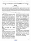
3.2.
Display
Gas Supply Valve
Fig.1. Block Diagram of Domestic Gas Billing
Digital meter is primary part of domestic billing
system; its hardware details are explained in following
sections.
3.1. Internal Structure of Digital Meter
Front Chamber
Value
2.5 m3/h
0.016 m3/h
1 bar
No pressure leakage
under 15 kpa
Counting Mechanism
The counting mechanism is responsible to record
the consumption of gas (in cubic meter per hour-m3/h).
Then this reading is used to calculate the gas
consumption bill. The higher the number of revolutions
to measure a cubic meter, the faster the meter is
operating, the greater potential for increased
component wear resulting in reduced meter life. The
measuring device may consist of pistons diaphragms or
of a fan wheel driven by the pressure of the gas and
connected to a counter mechanism [12].
It is a positive displacement meter operated by using
mechanical divisions to displace discrete volumes of
gas successively. All versions of positive displacement
meter are low friction, low maintenance and long life
Fig.3. Meter’s External Dial.
edges of gears are not smooth that’s why the output
pulses contain some ripples. Before inputting these
pulses into pulse counter, this was very important to
remove these ripples. Therefore we used pulse
conditioning through Schmitt trigger.
Amplitude
The gas meter consists of a box divided in two
compartments by a partition (Fig.2). Each compartment
is itself divided by a central diaphragm; the gas passes
successively in and out of these four compartments.
The alternating motion of the diaphragm drives the
assembly of gears. Then these gears rotate the wheels
of digits (Fig.3) [13].
Fig.4. Meter’s Internal Gear Assembly
Although the gas consumption is shown in digits (so
digital output of meter) but like digital systems this
output can’t be fed into some other digital systems to
save it or read by AMR technology. Therefore it was
necessary to digitize the analogue output of this meter.
This is explained in next section.
Fig.6. Digital Encoder and its Output
3.4. Pulse Conditioning
In our case, the ripples have high frequencies as
compared to the original waveform therefore we passed
this waveform from the Schmitt trigger circuit to get a
pure digital waveform (Fig.7).
3.3. Digitization
Unfiltered Digital Signal
Schmitt Trigger
Amplitude
The digitizing mechanism of an analogue meter is
the primary conversion from conventional analogue
method to a prepaid gas meter. Ultimately this feature
greatly enabled the meter to communicate with other
digital devices e.g. Remote Terminal Unit (RTU),
Prepaid Card Reader etc. To digitize the meter, an
encoder was designed which encodes (converts) the gas
consumption into cubic meter. This was done by
making precisely spaced holes in the main gear of the
meter. Then one IR transceiver was fitted across the
main gear. Now while operation, as the gear rotates, the
encoder calculates the digitally calculates the gas
consumption.
Time
Time
Ripple Free, Filtered Digital Signal
Fig 7. Schmitt Trigger, Filtering the Ripples
In case if pulse conditioning is not used then as a
result of one pulse the pulse counter triggers more than
ten times because it also senses the ripples and take
them as a complete logic. This results in wrong bill
calculations. That’s why its is necessary to use Schmitt
trigger so that as a result of one pulse, the pulse counter
should count only once.
3.5. Calculating the Gas Consumption
Fig.5. Main Gear, Fixed Inside the Meter
Using analogue to digital encoder, the meter
provided the digital output shown in Fig.6. But as the
The digital meter is supposed to output digital
pulses. That is why in our existing meter we converted
the revolution of gear into electrical pulses. In other
words, at deeper level these pulses are responsible to
8.7cm
calculate the gas consumption. In normal meters when
one gear rotates one revolution, the counter indicates
1m3 gas consumption. But in digital meter one
revolution of gas meter is equal to ten pulses..
Therefore when ten pulses are received to the processor
of meter, it displays (on LCD) that 1 m3 gas has been
consumed. This is also shown in following simple
mathematical relationship:
1 revolution (of gear) = 1 m3 gas consumed
1 revolution (of gear) = ten electrical pulses
So
Ten electrical pulses =1 m3 gas consumed
Note: As mentioned in previous paragraphs, that
ripples are necessary to be eliminated. But if we don’t
eliminate/reduce them (i.e. if we don’t use Schmitt
trigger) then 1-gear revolution would be equal to more
than ten electrical pulses. There may be case that 1gear revolution would be equal to 50 or more
electrical pulses. Therefore the result would be an
absolutely wrong calculation of gas consumption.
3.6. Gas Flow Control Valve
If prepaid balance is not enough, the meter has
ability to shutdown the gas supply by energizing its
solenoid valve. This valve is specially designed to stop
the flow of liquid/gas passing through it (Fig 8). This
valve is operated at 12W Power (12 V, 1A). When gas
supply is needed to stop, the controlling circuitry
energizes the amplifier, resulting in activating the relay
and turning OFF the valve.
Internal Solenoid
Outlet
Inlet
Fig.8. Gas Flow Control Valve
5.5cm
Copper Contacts
Fig.9. P-Card Layout
Unlike many other prepay cards this card is
reprogrammable. This feature is useful for the gas
supplier company. Because after using, the customers
would not throw the card and unloaded card would be
returned back to the company. This would help in
saving manufacturing cost of the card. Currently the
manufacturing cost of this P-card is Pak Rupees: 45
(0.75 US$).
3.8. P-Card Programmer
P-Card was designed to facilitate the gas provider
company, which is providing gas to domestic
consumers (with low gas consumption). This
programmer would enable the company to reload/ reuse
its P-cards.
3.9. P-Card Meter Charging
To charge the prepaid gas meter, the P-card is
inserted into the specific slot. The sensor inside this
slot can identify that whether the card is inserted in
proper way or not. Then password is entered using
keypad, fixed at the front panel of meter. On entering
correct password, the P-Card reader reads the balance
in the memory of P-Card and then it copies all of the
contents into the memory of the meter. In this way the
initial balance into the memory of meter is added with
the newer figures (Fig 10). After copying contents of
the card, the P-Card Writer washes all of the contents
the P-card, so that this can’t be used next time.
3.7. P-Card
The P-Card is a reprogrammable contact smart card
with memory. In the name P-Card, the P stands for
Programmable and Prepaid. In digital gas meter, this
card plays vital role because this holds gas units (meter
cubes) in the form of digital numbers. It also holds an
eight-digit password (Fig 9). While charging the meter,
the copper strip establishes contact of card circuitry
with meter circuitry. In this way it becomes very easy
to charge/recharge the meter
Processing
Unit
Fig.10. Meter Charging Process Through P-card
4. Industrial Billing
4.3. Data Logger Software
As industries use larger amount of gas/day than a
domestic user, therefore the prepaid meter was not
feasible. That’s why we wirelessly connected the
digital gas meter with the gas billing company. The
different modules of industrial billing are discussed
below.
This part of automated billing is responsible to
receive meter reading, calculate bill and then send back
the bill to the consumer. It further consists of four parts
(Fig.12 and Fig.14):
1. Data Receiver (Receives meter reading from
consumer site)
2. Bill Calculator (Calculate gas bill at central
gas billing office)
3. Bill and Notifications Transmitter (Dispatch
gas bill to consumer site)
4. Software Information (Names of System &
Authors)
4.1. Remote Terminal Unit (RTU)
The RTU is a hybrid of hardware and software and
contains many functional modules. The RTU is
providing connectivity with outer world by GSM
network (GSM modem is incorporated). The main
function is to provide generic solution for telemetry
and telemetics. Currently it is being used for remote
monitoring (remote data acquisition) and remote
control (turning ON/OFF the gas meter).
Start
Master Controller
No
GSM Modem
working
Yes
Equipment
Reporting
Available
SIM Space
No
Yes
No
Display and Turn
On Buzzer
SMS Received
Low Battery
Level
Yes
SMS Presence
Detector
No
Display and Turn
On Buzzer
Fig.11. Overview of Industrial Billing
Find SMS location
in SIM Memory
Read New SMS
4.2. Data Communication System
The RTU transmits data (meter reading) using GSM
network of any mobile service provider. For this
purpose a Subscriber Identity Module (SIM) is used.
After transmission, the data is received in the
central/regional billing office. The GSM Modem uses
specific antenna to wirelessly transmit the data to the
central/regional billing office. Following are the
specifications of antenna.
Table 2. Specifications ofOmni
GSM Power
Antenna3db GSM
Model
Antenna
Frequency Range
890-960 MHz
Gain
3dBi peak
Impedance
50 ohms
Beam Pattern
360 Degrees
Wind Survival Rating
100kph
Verify Password of
RTU
No
Display “Error”
Yes
Take Action
Change Password
Activate AMR
Module
Turn On/Off Gas
Meter
Record Meter
Reading
AMR’s Recording
Module
Record Time
Record Temperature
Transmitter Data
Fig.12. Software Flow Chart of RTU
Prepaid Card
Writer/Reader
EEPROM
Mechanical to Digital
Encoder
Processing Module
Prepaid Balance
Comparater
Schmitt
Trigger
Keypad
Digital Pulse
Counter
Display
Gas Supply Valve
SIM Card
GSM
Modem
Remote Terminal Unit
Fig.13. Hardware Flow Chart of RTU
Meter Communication
Server SIM Number
Data
Receiver
Storing Raw Data
Display
Meter Serial Number
Meter Current
Reading
Date and Time of
Meter
Current Temperature
Data
Receiver
Database
Monthly/Annual
Graph Display
Bar or Pie Graph
Gas Consumption
Graph
Total revenue graph
Gas Bill Amount
Notifications
Time and Date
Previous Reading
Current Reading
Difference of
Readings
Current Bill
Transmission
Bill and
Notification
Transmitter
Adjusting Last Date of Bill
Submission
Fig 14: Hierarchy Chart of Data Logger Software
View publication stats
This paper explored separate billing solutions for
domestic and industrial gas consumers. For domestic
consumers we designed a prepaid billing system while
for industrial ones we designed a postpaid but
wirelessly (GSM) controlled billing system. Such
system minimizes the human intervention in meter
reading, bill calculations and bill delivery which
ultimately reduces many defects, currently existing in
conventional manual billing systems. This system was
specially designed for Pakistan but can also be
implemented in any other country, where initially
manual billing is being used.
6. References
EEPROM
RTU Master
Controller
5. Conclusion
[1] B. S. Koay, S. S. Cheah, Y. H. Sng, P. H. J.
Chong, P. Shum, Y. C. Tong, “Design and
Implementation of Bluetooth Energy Meter”,
Nanyang Technological University, ICICS-PCM,
15-18 Dec 2003, 3A6.7, Singapore pp.1474-1476
[2] T. Meek, P. Chilese “Remote Meter Reading by
Radio - A European Perspective” Schlumberger
Industries, UK. pp 196-198
[3] Carl Brasek “Urban Utilities Warm Up to the Idea
of Wireless Automatic Meter Reading” IEE
Computing & Control Engineering December /
January 2004/05, pp.11-13
[4] Yan Liu, Rochelle A. Fischer and Noel N. Schulz,
“Distribution System Outage and Restoration
Analysis Using A Wireless AMR System”, 2002
IEEE, pp. 871-874
[5] Tian Yew Lim and Tat-Wai Chan “Experimenting
Remote Kilowatthour Meter Reading Through
Low-Voltage Power Lines at Dense Housing
Estates” IEEE Transactions on Power Delivery,
VOL. 17, NO. 3, July 2002. pp. 708-711
[6] Paul G. Honchar Sensus Metering Systems DuBois
Pan “Diaphragm Meters Applications, Installations
and Maintenance” 43rd CGA Gas Measurement
School, June 1-3, 2004.
[7] Terry Chandler “The Technology Development of
Automatic Metering and Monitoring Systems”
Terry Chandler Director of Engineering Power
Quality Thailand LTD and Power Quality Inc USA
[8] http://www.energycite.com/amr.htm
[9] www.elster-instromet.com/en/diaphragm_meters
[10] http://www.dncustoms.gov.vn/web_Eglish/BIEU_
THUE/E_HTM/E9028.htm
[11] http://www.pipelineandgastechnology.com/0106u
tilityoperations.html
[12] http://www.dncustoms.gov.vn/web_Eglish/BIEU_
THUE/E_HTM/E9028.htm
Academia.edu no longer supports Internet Explorer.
To browse Academia.edu and the wider internet faster and more securely, please take a few seconds to upgrade your browser.
Design and Implementation of Smart Billing and Automated Meter Reading System for Utility Gas
2007 International Conference on Information and Emerging Technologies, 2007
By Rana Ali
...Read more
Related Papers


Advances in Intelligent Systems and Computing, 2014
Download

2015 International Conference on Informatics, Electronics & Vision (ICIEV), 2015
Download


Download


Download

Bari e il suo mare dal Rinascimento al Novecento, 2022
Download