Towards Model-Based AHMI Development
Juan González-Calleros, Jean Vanderdonckt
Université catholique de Louvain
Place des Doyens 1, 1348
Louvain-la-Neuve, BELGIUM
+32 (0)1 047 8349
Andreas Lüdtke, Jan-Patrick Osterloh
OFFIS e.V.,
Escherweg 2, 26127
Oldenburg, GERMANY
+49 (0)441 972 2530
{juan.m.gonzalez, jean.vanderdonckt}@uclouvain.be
{luedtke, osterloh}@offis.de
ABSTRACT
Aircraft cockpit system design is an activity with several
challenges, particularly when new technologies break with
previous user experience. This is the case with the design
of the advanced human machine interface (AHMI), used
for controlling the Advanced Flight Management System
(AFMS), which has been developed by the German
Aerospace Center (DLR). Studying this new User Interface
(UI) requires a structured approach to evaluate and validate
AHMI designs. In this paper, we introduce a model-based
development process for AHMI development, based on our
research in the EUs 7th framework project “Human”.
Categories and Subject Descriptors
D2.2 [Software Engineering]: Design Tools and Techniques –
Modules and interfaces; user interfaces. D2.m [Software
Engineering]: Miscellaneous – Rapid Prototyping; reusable
software. H.1.2 [Information Systems]: Models and Principles –
User/Machine Systems. H5.2 [Information interfaces and
presentation]: User Interfaces – Prototyping; user-centered
design; user interface management systems (UIMS).
Keywords
User Interface, Advanced Human Machine Interface, ModelBased User Interface Development, Cockpit design, UserCentered Design.
INTRODUCTION
The AFMS is a piece of software that helps pilots to
manage their flight in terms of trajectory production (e.g.
generate trajectories out of a constraint list). The AFMS
can be handled via a new system called Advanced Human
Machine Interface (AHMI) [15]. The interaction between
the pilot and the AHMI is through the different User
Interfaces (UIs) that composed the AHMI, which is
composed of traditional control objects (buttons, spin
button, menu) and non-traditional controls (compass rose,
aircraft). The transformation of the existing character-based
Permission to make digital or hard copies of all or part of this work for
personal or classroom use is granted without fee provided that copies are
not made or distributed for profit or commercial advantage and that copies
bear this notice and the full citation on the first page. To copy otherwise, or
republish, to post on servers or to redistribute to lists, requires prior specific
permission and/or a fee.
HCI-Aero 2010, November 3-5, 2010, Cape Canaveral, Florida, USA.
Copyright 2010 ACM 978-1-60558-246-7/09/04...$5.00.
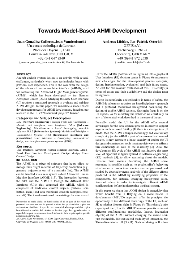
UI for the AFMS (bottom left in Figure 6) into a graphical
User Interface (UI) (bottom center in Figure 6) encounters
new challenges for the development process (analysis,
design, implementation, evaluation) and their future usage.
At least for two reasons: evaluation of this UI is costly (in
terms of assets and their availability) and the design must
be rigorous.
Due to its complexity and criticality in terms of safety, the
AHMI development requires an interdisciplinary approach
and a profound theoretical background, facilitating the
design of usable AHMI systems. Our main focus is on the
UI aspects, as for modeling the behavior we could rely on
any of the related work described in the state of the art.
Formally model the UI for the AHMI offer several
advantages for the development process in order to support
aspects such as: modifiability (If there is a change in a UI
model then the AHMI changes accordingly and vice versa);
complexity (as the AHMI is part of a command and control
system, it may represent a huge quantity of code); the UI
design and construction tools must provide ways to address
this complexity as well as the reliability [3]. Also, the
development life cycle of the AHMI must involve the same
level of rigor that is typically used in software engineering
(SE) methods [5], to allow reasoning about the models.
Because from models describing the AHMI some
reasoning is possible, such as: to predict pilot’s behavior;
simulate error production; models can be processed and
studied by devoted systems; analysis of the different effects
produced in the AHMI by modifying properties of the
components, for instance, changing background color,
fonts of labels, in order to investigate different AHMI
configurations before implementing the final system.
In this paper we claim that AHMI design is an activity that
would benefit from a Relying on a model-based UI
development (MBUID) approach offer, in principle, the
opportunity to test different renderings of the UI, such as:
3D rendering (bottom right in Figure 6). This chameleonic
capacity of the UI in the MBUID context permits us to test
different configurations (modalities, layout, interaction
objects) of the AHMI without changing the source code
just the models. We test second modality of interaction, the
Three-dimensional UI (3DUI). Such rendering will allow
�us to explore the impact of representing physical aspects
like a button pressed depicting the engage mode activated.
The reminder of this paper includes the review of the state
of the art in the next section. Followed by, the description
of the proposed methodology. Next, the methodology is
exemplified through a case study. Finally, the conclusions
and future directions of this research are presented.
STATE OF THE ART
Formal methods have been used in aviation for different
purposes. Interactive Cooperative Objects (ICOs) [16], has
been used to model: air traffic workstations, civil aircraft
cockpit and military aircraft cockpit. ICO's is a formal
approach for user interaction reconfiguration of safety
critical interactive systems, addressing problems were
pilots are confronted with several display units. This work
addresses usability issues (improving the ways in which
operators can reach their goals while interacting with the
system) by increasing the reliability of the system using
diverse configuration both for input and output devices.
The interest is also on modeling behavior of the system and
nothing about the UI in particular. Even that they work on
multiple displays, they are assumed to be simple as there is
a limited use of widgets for those displays, so no particular
attention is paid to the different UI configurations.
A formal model of pilot-automation interaction and the
characteristics of the UI are described in [17]. This work
compared the effects and benefits of visual cues (labels,
prompts, messages) to support mission tasks. Similar to
previous works, the set of widgets here is limited and no
attention was paid to the UI to be designed.
The ARINC standard [1] defines protocols to communicate
the dialogue and the functional core of cockpit display
system. This standard also considers the presentation level,
i.e., a set of widgets that can be used in any display unit in
the cockpit. The set of widgets corresponds to the classical
list of WIMP but no design guidelines is included as part of
the standard. Every user of the standard is free to use it as
its own convenience. This has been identified as an issue
by [2]: "the ARINC does not provide any method to design
UIs". Even more, in [16] a limitation of the standard is
emphasized: "the ARINC is not used for primary cockpit
applications, such as Primary Flight Display and
Navigation Display. It only deals with secondary
applications involved in the management of the flight such
as the ones allocated to the Multiple Control Display Unit".
Several work on formal methods has been reported.
However there is always a focus on the dynamic aspects of
the systems and their interrelation with the aircraft but
limited or none attention has been paid to the UI. This was
reinforced by the fact that the UI used were not complex at
all and were more use to show information rather than to
interact with the system. The introduction of the AHMI
falls into a new category that has not been considered in the
related work. Moreover, the design knowledge to support
the design of highly interactive systems, such as the AHMI,
is not possible based on current methods, they just rely on a
very limited set of classical WIMP interfaces [4]. In the
next section we propose a methodology for developing
AHMI systems and described some of its benefits.
MODEL-BASED AHMI DEVELOPMENT
In the context of Model-Based Development of Interactive
Systems, there is a global consensus about the components
of a User Interface (UI) development methodology [21]
which are: a series of models, a language, an approach and
a suite of software engineering tools.. The proposed
method is compliant with the structured CAMELEON
reference framework [7]. Largely used in the literature for
UI development, the CAMELEON reference framework
adheres to the Model Driven Architecture (MDA) that has
been applied widely to address the development of
complex systems, Figure 6. The next subsections details
how these components are defined and contextualized in a
structured framework that is detailed in the next section
along with the case study.
Models
A formal underpinning for describing models in a set of
meta-models facilitates meaningful integration and
transformation among models, and is the basis for
automation through software. Models are represented as a
UML class diagram that then can be specified using the
USer Interface eXtensible Markup Language (UsiXML)
[10]. The Concrete User Interface Model (CUI) allows
both the specification of the presentation and the behavior
of an AHMI with elements that can be perceived by the
users [11]. The CUI model is an abstraction of AHMI
elements some of which are independent of programming
toolkit. The AHMI includes objects in the UI that are
different from those found in traditional toolkits, such as:
maps, aircrafts, airports, trajectories, navigation aids.
Different tools require a standard for consistency in the
information they exchange. Transferring knowledge,
building interfaces between agents (humans or artifacts) is
a crucial task for future applications in aeronautics. Focus
must be on the exchange of knowledge across applications
and document format boundaries; “a common pool of
knowledge is needed where everybody may share and
retrieve knowledge” [16]. As models can easily grow over
time, it is known that scalability of the approaches to deal
with real-life and real size applications can often confront
difficulties, due to the size and the number of models that
are constructed and managed [3]. In summary, a well
structured model can be incremented better.
Language
A language facilitates communication between the different
software modules that are used during the development
process of the AHMI. To express models a User Interface
Description Language (UIDL) is needed. In this research
we selected USIXML [10], among other reasons, because it
is open that means everybody can have access to it for no
cost. Also, in order to introduce an extension in other
�UIDL language, a long process must be followed, that is
not necessarily successful. UsiXML follows a language
engineering approach as it considers: the syntax, semantics
and stylistics of the language [21]. The semantics are
expressed as UML class diagrams that correspond to
metamodels of the models of the AHMI. The models
defined in the previous section are transformed in a
UsiXML specification, which considers XML Schemas
(abstract syntax) for the definition of valid XML. Finally
the stylistics is the visual syntax mainly used to depict
almost all the models defined in the ontology; there is a
graphical representation for them. There is a complete
review of UIDLs that can be used instead of UsiXML that
can be found in [8].
After selecting the negotiation type the system show the
feedback from ATC about the trajectory.
A systematic method is recommended to drive the
development life cycle to guarantee some form of quality
of the resulting software system. We will describe the
method with the development of the navigation display
(ND) of the AHMI.
Thereafter, even if the negotiation has failed, a click on
ENGAGE! (trigger trajectory engage) activates the AFMS
guidance, which generates aircraft control commands to
guide the aircraft along the generated trajectory. The
trajectory is then displayed as a solid green line (show
trajectory). If the trajectory is approved by ATC and
engaged, i.e. the AFMS guides the aircraft along that
trajectory, the dark grey background of the trajectory
changes to a bright grey one. One relevant aspect of relying
on task models revealed a usability problem on the existing
system. The current version of the AHMI allows pilots to
trigger any of the three actions (select, negotiate and
engage trajectory) without forcing a logical sequence of the
tasks. Interaction objects are enabled even that they should
not be. The task model structure and task model
relationships assures, at some point, to consider the logical
sequence of actions as constraints for the further
concretization of the tasks.
Step 1: AHMI Task Model
Step 2: AHMI Abstract User Interface
There are more than fifty direct actions that can be
manipulated on the AHMI. As there is no significant
difference on what it corresponds to UI objects and layout.
We will restrict to one task, although, the rest of the UI
can be generated by analogy. The task that we will focus is
the generation of a new trajectory in the air (Figure 1). To
generate a trajectory in the air, the user has to select a
waypoint on the constraint list to which the aircraft shall fly
directly and at which it shall intercept the constraint list.
The AHMI automatically suggests a suitable waypoint that
is written in a field above the DIRTO button, whenever the
mouse pointer is moved over that button. By pressing on
the field above the DIRTO button, the user accepts the
suggestion (trigger suitable waypoint). After clicking on
the waypoint or the field with the suggested waypoint’s
name, a trajectory leading from the current position to the
intercept point and from there on along the constraint list is
generated (system tasks of the subtree create arbitrary
trajectory). While the constraint list is shown as a blue line,
the trajectory is shown now as a green dotted line.
Defining the AHMI as an Abstract User Interface (AUI)
model provides design means to further evaluate different
modalities of interaction for the AHMI. For instance, the
physical device used as FMS is different from the AHMI
but their abstract interfaces have some similarities and
access the same tasks. We did not investigate further this
level of abstraction as the interest was on modeling the
graphical representation of the AHMI.
Method
To select another waypoint, the user simply has to click
first on the DIRTO button (create waypoint) and then move
the mouse onto the waypoint on the constraint list he
wishes to select. The waypoint’s name is then marked in
yellow and written on the DIRTO button (select arbitrary
waypoint). Special attention must be take to the calculate
trajectory feedback as more than once a WP can be selected
then if one WP was selected a trajectory is proposed but if
another WP is selected then the previous trajectory is
deleted and the new proposed trajectory is drawn. After the
trajectory has been generated, it can be negotiated with
ATC simply by moving the mouse over the SEND TO
ATC menu. A priority could be chosen during the
negotiation process with ATC (select negotiation type).
Step 3: AHMI Concrete User Interface Modeling
The Concrete User Interface (CUI) refers to the modeling
of the solution independent on the platform or the
implementation language but we know the modality of
interaction, graphical. In Figure 2 the ND layout mock-up
is shown. At the upper edge are the buttons that control the
view mode, e.g. lateral or vertical view. At the left edge are
the buttons that control the display mode, e.g. the range of
the map or what kind of information is shown on the map.
The buttons that control the generation and negotiation of a
trajectory are at the lower edge of the display. The buttons
at the right edge and in the upper right corner of the display
are used for creating and editing constraint lists.
Additionally, there is a “cancel”-button in the lower left
corner of the display with a yellow cross on it and an
“accept”-button in the lower right corner with a green
check mark on it. The AHMI user interface actions were
analyzed in detail to determine relevant interactions, from
the cognitive architecture point of view, with the AHMI.
The behavior formalization refers to the way to express the
functional part. The behavior is the description of an eventresponse mechanism that results in a system state change.
The specification of behavior may be decomposed into
three types of elements: an event, a condition, and an action
(ECA rules).
�Figure 1. Task Model of the create trajectory task
Figure 2. Mock-up of the Navigation Display layout
Figure 3. Navigation Display rendered as a 3DUI.
The ECA rules are expressed as tables (Figure 5). The
condition (including system states) are expressions if the
format if then else. The action is method calls in the body
of the algorithm. The event is always a mouse click. Due to
the large number of actions an example is used to illustrate
this process. To select a priority during the downlink of
trajectory it can be negotiated with the air traffic controller
(ATC) simply by selecting the type trajectory on the SEND
TO ATC menu.
More than fifty system behaviors have been modeled for
the SAHMI that will be used in the simulation
environment.
A priority could be chosen during the negotiation process
with ATC. There are five priorities: Normal, Emergency,
Technical, Weather, and Scheduling/Traffic. For this
example just the schedule behavior modeling is presented,
the others can be generated by analogy, as they keep the
same structure. A method call occurs when an action is
triggered by the event click with a mouse on the menu Item
negotiating schedule trajectory. There is no particular
condition to be evaluated.
Step 4: Final User Interface
So far, the example has illustrated the different steps but no
constraint has been discussed related to the concretization
of the model. Evidently for this particular example, our
first step was to abstract the real system functionality and
representation (2D). A possible final rendering of the
AHMI in 3D (Figure 3) right now is just about the
presentation. Although, it is out of the scope of this work
further investigation will be conducted to evaluate the
impact of this representation. Trying to address questions
such as: the navigation compass rose would have an impact
or not while being in 3D? A 3D rendering of the different
views (vertical or lateral) are preferred by pilots?
�BENEFITS FROM RELYING ON A MODEL-BASED
DEVELOPMENT
Integrating evaluation in the loop of the design of the
AHMI imply the use of pilots and a simulator. Different
methods exist for evaluating a UI which mainly are divided
in two categories: qualitative and quantitative approaches.
Crew preferences and all kind of subjective data are
gathered using different means, for instance questionnaires.
There is always the need for crew members to provide
feedback on the UI. Unfortunately, pilots are assets that are
hard to find, so include them in the loop for constant UI
evaluation is not feasible [17].
In a simulation environment where pilots are substitute by
cognitive models [12,13], and a physical simulation
platform by a virtual simulation environment, automatic
evaluation of the UI can be done by including a UI
evaluation layer to the simulation environment [8]. A
repository with UsiXML formalism describing the AHMI
is used. The UI is complemented with dynamic (state of a
button during the interaction, color of the label) and static
(UI layout, position of objects) data accessed via the
simulation system. The Cognitive Architecture (CA) is
used to simulate pilots’ interaction with the AHMI. More
details on the CA or the experiments are out of the scope of
this paper, they can be found in [12,13]. Simulated pilots
actions over the UI are passed as messages that are
processed. This data from the simulation system must be
transformed to be compatible with UsiXML format. This
data is store as a log File history.
A UsiXML specification can be changed for another. This
is illustrated in Figure 4 in A) a set of toggle buttons are
used to show/hide objects on the navigation map. In B) this
buttons are replaced by a series of checkboxes. From this
example it can be identified that the visual obstruction of
the toggle buttons is reduced by their replacement of a
checkboxes group. The UI could be composed of different
version of the UI to perform the same task. Before
implementing all different version, some test can be
performed to analyze the UI. Selecting the appropriate
interaction object is based on guidelines proposed in [6].
Evaluation of the User Interface is vital for the success of
an application. Also, we have used the semantics of the
AHMI formalized with UsiXML to evaluate the UI against
guidelines [8]. Special attention was paid to those
guidelines for standard certification and quality assurance
and to express them in the Guideline Definition Language
(GDL) [20], a XML-compliant language that is directly
linked to UsiXML. Three aspects of the UI can be
evaluated: usability accordingly to guidelines, workload
and expected execution time. Guidelines evaluation can be
automatically performed with the Usability Adviser [19].
The idea is that an evaluation layer over Symbolic AHMI
(SAHMI) keeps a trace of the evolution of the UI during
the interaction with the cognitive architecture. Such
evaluation can be automatically evaluated with the
Usability Adviser [19], a tool to determine the ergonomics
characteristics of a UI when it is coded in UsiXML. This
tool evaluates ergonomic rules to determine workload,
visual obstruction, among other features.
A
B
Figure 4 Selection of interaction objects
This software expresses usability guidelines as logical
grammars. For example, a usability guideline that selects
appropriate color combinations for the label on a slider, is
described as follows: i
Slider :
(SliderColor(i,white)
LabelColor (i,yellow)).
The AHMI must not differ from a traditional UI. The
traditional set of widgets must be used for the AHMI UI as
much as possible by imitating their behavior and graphical
representation. This is needed as future pilots would be
used to the computer interaction, thus, cockpit display
systems should at least be consistent with systems of our
daily life [17]. Even more important, traditional UI
usability guidelines such as those listed in the ISO 9126
standard can be used to evaluate elements of the AHMI UI.
There are some which have been corroborated in the
avionics domain, for instance, messages should follow
always the nomenclature: first letter in capital and the rest
in lower case [17]. There are some other that refers to
�specific AHMI display systems such as the consistency in
the roll index in the compass rose [18].
CONCLUSIONS
The AHMI is a new innovative system that introduces new
challenges for the development of cockpit systems.
Development steps including design and evaluation, among
others, are normally limited addressed when it refers to the
UI. Design knowledge is normally hidden and evaluation is
mostly focused on the system functionality rather than of
the usability of the system. In this paper we propose to rely
on a model-driven approach for the development of AHMI
that, among other advantages, can be coupled in a
simulation environment. Modeling the SAHMI showed to
be an option for UI evaluation. The model of the UI, as
described in the paper, can be modified in order to test
different UI configurations. Traditional measurements can
be assessed like UI workload, color combination. Finally,
the modality of interaction of the UI can be object of
evaluation. While in this paper we showed how the original
2D rendering can be equally rendered in 3D. A future plan
is to automatically generate the AHMI from its model and
to submit it to run-time analysis. For the moment, only
automated guideline review in perform through the
UsabilityAdvisor. Theoretically, workload [5,14] and task
execution time [10] can be evaluated manually on the UI
based on some parameters assigned to the visible elements
of the UI. We will work on this extension to the automatic
evaluation tool as a future work.
ACKNOWLEDGMENTS
We gratefully acknowledge the support of the Human
European project (Model based Analysis of Human Errors
during Aircraft Cockpit System Design - FP7-AAT-2007RTD-1/CP-FP-211988) funded by the European Commission) and the ITEA2 Call 3 UsiXML project under
reference 20080026, funded by Région Wallonne.
REFERENCES
1. ARINC 661-2, Prepared by Airlines Electronic
Engineering Committee. Cockpit Display System
Interfaces to User Systems. ARINC Specification 6612, 2005.
2. Barboni, E., Navarre, D., Palanque P. & Basnyat, S. A
Formal Description Technique for Interactive Cockpit
Applications Compliant with ARINC Specification 661.
In proceedings of SIES 2007 - IEEE 2th International
Symposium on Industrial Embedded Systems July 4-6,
2007, Lisbon, Portugal.
3. Barboni, E., Navarre, D., Palanque P. & Basnyat, S.
Exploitation of Formal Specification Techniques for
ARINC 661 Interactive Cockpit Applications.
Proceedings of HCI aero conference, (HCI Aero 2006),
Seatle, USA, Sept. 2006. p81-89
4. Barboni, E., Conversy, S., Navarre D. & Palanque, P.
Model-Based
Engineering
of
Widgets, User
Applications and Servers Compliant with ARINC 661
Specification. Proceedings of the 13th conference on
Design Specification and Verification of Interactive
Systems (DSVIS 2006), LNCS, Springer Verlag.
5. Bierbaum, C.R., Szabo, S.M. Aldrich, T.B. Task
analysis of the UH-60 mission and decision rules for
developing a UH-60 workload prediction model,
Volume 1: Summary report (AD-A210 763).
Alexandria, VA: U.S. Army Research Institute for the
behavioral and Social Sciences.
6. Bodart, F. and Vanderdonckt, J. (1994), On the Problem
of Selecting Interaction Objects, Proc. of BCS Conf.
HCI’94 "People and Computers IX" (Glasgow, 23-26
August 1994), G. Cockton, S.W. Draper, G.R.S. Weir
(eds.), Cambridge University Press, Cambridge, 1994,
pp. 163-178.
7. Calvary, G., Coutaz, J., Thevenin, D., Limbourg, Q.,
Bouillon, L., Vanderdonckt, J.: A Unifying Reference
Framework for Multi-Target User Interfaces.
Interacting with Computers, Vol. 15, No. 3, June 2003
289–308.
8. Gonzalez Calleros, J.M., Vanderdonckt, J., Lüdtke, A.,
Osterloh, J.P., Towards Model-Based AHMI Automatic
Evaluation, In: Proc. of 1st Workshop on Human
Human Modelling in Assisted Transportation
(HMAT'2010), Belgirate, Italy, June 30- July 2, 2010.
Springer-Verlag, Berlin.
9. Guerrero García, J., González Calleros, J.M.,
Vanderdonckt, J., Muñoz Arteaga, J. A Theoretical
Survey of User Interface Description Languages:
Preliminary Results, Proc. of Joint 4th Latin American
Conference on Human-Computer Interaction-7th Latin
American Web Congress LA-Web/CLIHC'2009
(Merida, November 9-11, 2009), E. Chavez, E. Furtado,
A. Moran (Eds.), IEEE Computer Society Press, Los
Alamitos, 2009, pp. 36-43.
10. Lepreux, S., Vanderdonckt, J., Towards a support of the
user interfaces design using composition rules. Proc. of
6th Int. Conf. on Computer-Aided Design of User
Interfaces CADUI'2006 (Bucharest, 6-8 June 2006),
Springer-Verlag, Berlin, pp. 231-244.
11. Limbourg, Q., Vanderdonckt, J., Michotte, B., Bouillon,
L., Lopez, V.: UsiXML: a Language Supporting MultiPath Development of User Interfaces. In: Proc. of 9th
IFIP Working Conference on Engineering for HumanComputer Interaction jointly with 11th Int. Workshop
on Design, Specification, and Verification of Interactive
Systems EHCIDSVIS’2004 (Hamburg, July 11-13,
2004). Springer-Verlag, Berlin (2005).
12. Lüdtke, A., Weber, L., Osterloh, J.P., Wortelen, B.,
Modeling Pilot and Driver Behavior for Human Error
Simulation. HCI (11) 2009: 403-412.
13. Lüdtke, A., Osterloh, J.P., Simulating Perceptive
Processes of Pilots to Support System Design, In Proc.
�12th IFIP TC 13 International Conference (Interact
2009), Uppsala, Sweden, August 24-28, 2009, pp. 471484.
14. McCracken, J.H., Aldrich, T.B., Analyses of selected
LHX mission functions: Implications for operator
workload and system automation goals (Technical Note
ASI479-024-84). Fort Rucker, AL: U.S. Army Research
Institute Aviation Research and Development Activity.
15. Mollwitz, V. AFMS Handbook for Users. Deutsches
Zentrum für Luft- und Raumfahrt e.V. (DLR). June
2006.
16. Navarre, D., Palanque, Ladry, J.F., Barboni, E., ICOs:
A Model-Based User Interface Description Technique
dedicated to Interactive Systems Addressing Usability,
Reliability and Scalability, In: Transactions on
Computer-Human Interaction, ACM SIGCHI, USA,
Special issue User Interface Description Languages for
Next Generation User Interfaces, ACM Press, 16(4),
2009, pp. 18:1-56.
17. Singer, G. and Dekker, S., The ergonomics of flight
management systems: fixing holes in the cockpit
certification net. Applied Ergonomics, 32 (3), p.247254, Jun 2001.
18. Singer, G. and Dekker, S., The effect of the roll index
(sky pointers on roll reversal errors. Human Factors and
Aerospace Safety, 2 (1), p.33-43, 2002.
19. Vanden Bossche, P., Développement d'un outil de
critique d'interface intelligent : UsabilityAdviser, M.Sc.
thesis, Université catholique de Louvain, Louvain-laNeuve, 1 September 2006.
20. Vanderdonckt, J., Beirekdar, A., & NoirhommeFraiture, M. (2004) “Automated Evaluation of Web
Usability And Accrssibility by Guideline Review”, In:
Proc. of 4th Int. Conf. on Web Engineering ICWE’04
(Munich, 28-30 July 2004), Springer-Verlag, Berlin, pp.
17–30.
21. Vanderdonckt, J., A MDA-Compliant Environment for
Developing User Interfaces of Information Systems,
Proc. of 17th Conf. on Advanced Information Systems
Engineering CAiSE'05 (Porto, 13-17 June 2005), O.
Pastor & J. Falcão e Cunha (eds.), Lecture Notes in
Computer Science, Vol. 3520, Springer-Verlag, Berlin,
2005, pp. 16-31.
Figure 5. Excerpt of the list of UI actions identified for the AHMI: Generating trajectory
�Figure 6. Model-Based Development steps of the AHMI
�
 Juan Manuel Gonzalez Calleros