Non-traditional machining utilizes energy sources other than mechanical force to remove material, such as electrical, chemical, and optical sources. It includes processes like ultrasonic machining, waterjet machining, abrasive jet machining, chemical machining, electrochemical machining, electrical discharge machining, and laser/electron-beam machining. Non-traditional machining is used for hard or heat-sensitive materials, complex part shapes, and when high precision is required. It removes material using mechanisms like erosion, dissolution, melting/vaporization rather than shearing.
This document discusses micro and nano manufacturing techniques such as micro turning, micro drilling, and micro milling. Micro turning can produce mirror surfaces with less than 10 nm surface roughness and is used to machine hard materials without subsurface damage. Micro drills as small as 5-50 μm in diameter are used to drill holes in PCBs, inkjet printer nozzles, and other applications. Micro milling is capable of creating 3D features from a few microns to hundreds of microns in size and drilling holes tens of microns in size. Machine tools such as ultra-precision lathes, Swiss-type lathes, and spindles with speeds over 500,000 rpm are used to enable these micro manufacturing processes.
The document discusses Electrical Discharge Machining (EDM). EDM is a manufacturing process where a desired shape is obtained by removing material from a workpiece using electrical discharges between two electrodes separated by a dielectric liquid. As the distance between the electrodes is reduced, current flows due to dielectric breakdown causing material removal from both electrodes. EDM was invented in the 1940s and has since improved, increasing machining speeds and reducing costs. EDM can machine hard metals and intricate shapes without needing to soften the material. The main components of an EDM system are the power supply, dielectric medium, workpiece and tool electrodes, and servo control unit. Material is removed through the formation and collapse of plasma channels between the electrodes during
This document discusses advanced machining processes, which utilize chemical, electrical, or high-energy beams to remove material as they are needed for difficult-to-machine materials or complex part geometries. It introduces various advanced processes like chemical machining, electrochemical machining, electrical discharge machining, laser beam machining, electron beam machining, and others. These processes allow machining of very hard materials, brittle materials, or parts that are too small, complex, or fragile for traditional machining techniques.
The material removal in EDM occurs due to the formation and collapse of plasma channels between the tool and workpiece. When a potential difference is applied, electrons are emitted from the tool and strike the workpiece, generating heat and forming craters. The main components of an EDM system are a power supply, workpiece and tool made of conductive materials, a dielectric medium like kerosene or water, and a servo control unit. Process parameters like voltage, current, pulse duration, and spark gap influence the material removal rate and surface finish. EDM can machine hard metals and complex shapes that other methods have difficulty with.
Shape memory alloys are metal alloys that can be deformed at one temperature but return to their original shape when heated or cooled. The most common alloys are nickel-titanium (Nitinol), copper-zinc-aluminum, and copper-aluminum-nickel. Nitinol was discovered in the 1960s and is now used widely in applications such as medical devices, aircraft, and household appliances. Shape memory alloys work through a solid state phase change between martensite and austenite phases - deforming occurs in the martensite phase while heating triggers shape recovery in the austenite phase. They provide advantages like biocompatibility and diverse applications but also
Non-conventional machining techniques such as EDM, ECM, laser beam machining, electron beam machining, and plasma arc machining remove material using thermoelectric or chemical processes instead of mechanical cutting. They allow machining of hard metals and complex shapes but require specialized equipment. Conventional machining relies on mechanical forces and contact between a harder cutting tool and workpiece, while non-conventional techniques use energy sources like electrical discharge, laser, electron beam, or plasma arc along with chemical etching to remove material layer-by-layer.
Working of Laser beam machining process. Its one kind of non traditional or advanced manufacturing process.Production of laser beam and with the use of lasers how can material can be removed is to be explained over here...
This is the 5th in our weekly series overviewing the different grades of titanium. Ti-6Al-4V or Titanium Grade 5 is hands down the most utilized alloy of titanium world wide. Over fifty percent of the worlds usage of titanium consists of Ti 5. In this presentation, you will learn about the applications of Ti5 (and titanium) as well as the different product forms it commonly comes in and given resources on where to buy titanium or learn more about this amazing metal.
Take a look and share if you like what you see!
The document discusses electrolytic in-process dressing (ELID), which uses electrolysis during grinding to maintain large grain protrusions and grit density on grinding wheels. There are different methods of ELID grinding, including using an electrode or the workpiece itself as the electrode. ELID reduces grinding forces and improves surface finish. It has applications in grinding structural ceramics, optics, and other precision components.
EDM is an electrical discharge machining process that uses electrical sparks to erode materials to shape and cut electrically conductive materials, even very hard metals. It has various applications in industries like molds, dies, aerospace where complex shapes are required. While EDM allows machining hard metals and complex shapes, it has slow material removal rates and high power consumption compared to traditional machining.
Water jet machine adalah mesin yang memotong bahan menggunakan air bertekanan tinggi yang dikeluarkan melalui nozzle kecil. Air bertekanan tinggi mampu memotong berbagai jenis bahan dengan kecepatan hingga 900 m/s. Water jet machine dianggap ramah lingkungan karena prosesnya tidak menghasilkan emisi berbahaya dan air serta abrasive yang digunakan dapat didaur ulang.
Water jet machining uses a high pressure stream of water, sometimes with an abrasive additive, to cut materials. Key aspects of the process include a water jet that travels at speeds of 540-1400 m/s to erode material from the workpiece surface. Parameters like pressure, abrasive grain size, and speed affect the performance and quality of cuts. Water jet machining provides advantages like flexibility, environmental friendliness, and stress-free cuts of many materials without heat or debris. However, initial costs can be high and material removal rates are low.
Laser beam welding is an advanced welding method that uses the heat generated by a laser beam to join two components. The laser beam penetrates the upper material and is absorbed by the lower material, heating it up directly. This heat is then conducted to the upper layer, melting both materials. A pumping unit provides energy to the laser medium, exciting its atoms to emit stimulated light. This beam is focused onto the components to generate localized heat and form the weld. Laser beam welding offers advantages like welding metals and non-metals without an electrode and ability to weld small, hard-to-reach areas. However, its initial costs are high and the process can be slow.
This document summarizes Prodintec's micromilling technology capabilities. Micromilling is a high precision machining process that can create complex geometries with features as small as microns. Prodintec has equipment that can micromill a wide range of materials with a precision of 2 microns using CAD/CAM software and CNC programming. Their facilities include machines with precision positioning and measurement systems to control and verify the micromilling process.
This document discusses electron beam micromachining (EBM), which uses a focused beam of high-velocity electrons to remove material from a workpiece through melting and vaporization. It describes the mechanism of material removal in EBM, where an electron beam generates a stream of electrons that heat the workpiece surface intensely. EBM can drill small holes, cut contours and slots, and is used in industries like aerospace, medical, and electronics. Some advantages are its ability to machine both conductive and non-conductive materials with no contact and very low tool wear. However, it requires vacuum and has high costs.
Water jet cutting is a machining method that uses a high-pressure stream of water, sometimes with an abrasive material added, to cut materials. It is a non-thermal process so there is no heat affected zone on the material. Water jet cutting can cut a variety of materials either with just water or by mixing in an abrasive material for harder substrates. It has advantages over other cutting methods in that it produces no heat, fumes or burrs and can cut many material types, but has limitations in cutting speed for some harder materials.
Spot welding is a metal joining process where two metal surfaces are welded together by resistance heating when a large current is passed through them. The current causes the metal to heat up and melt together. It allows for quick and easy welding of multiple metal sheets simultaneously without filler metals or flames. However, spot welds have lower strength than other weld types and repairs can be difficult. It is commonly used in the automobile industry to join metal car body panels and parts.
Isostatic pressing is a powder metallurgy technique that applies equal pressure in all directions to compact powdered materials. There are three main types - cold isostatic pressing, hot isostatic pressing, and warm isostatic pressing. Isostatic pressing allows for high density and uniform compaction of materials without the need for lubricants. It can be used to compact difficult materials like superalloys. The global isostatic pressing market was valued at $5.72 billion in 2017 and is projected to reach $9.22 billion by 2023, growing at a CAGR of 8.08% due to increasing demand for high-density 3D printed parts and investment in aerospace and defense applications
1. Cold working is the plastic deformation of metals at a temperature below the recrystallization temperature, while hot working occurs above the recrystallization temperature.
2. Metal spinning is a metalworking process that forms an axially symmetric part by rotating a disc or tube of metal at high speed against a spinning roller. It can be done by hand or CNC lathe.
3. Forging processes like upsetting, heading, blocking, and fullering are used to refine the shape of metals for finishing. Punching and blanking are shearing processes used to produce holes.
Electro Stream Drilling (ESD) is an electrochemical machining process that uses a high velocity stream of negatively charged acidic electrolyte to drill small diameter holes. It can drill holes between 0.127-0.89 mm using a voltage of 150-850 V. Unlike conventional electrochemical drilling, debris dissolved in the acidic electrolyte prevents clogging. ESD can drill deep and accurate holes through either dwell drilling or penetration drilling methods and offers advantages like high aspect ratio holes, low surface roughness, and no burrs or residual stresses. However, it has high initial costs and is limited to electrically conductive materials.
Electric discharge machining (EDM) is a machining process that uses electrical sparks to erode metals. It works by maintaining a precise gap between an electrode tool and a metal workpiece submerged in a dielectric fluid. Repeated electrical sparks are generated to melt and vaporize small amounts of metal from both the tool and workpiece, allowing complex and hard-to-machine shapes to be produced. EDM can machine metals regardless of hardness and without mechanical force, giving it advantages over traditional machining methods for difficult-to-cut materials.
This document summarizes a seminar presentation on ceramic matrix composites (CMCs). CMCs consist of a ceramic matrix with reinforcements. They offer advantages over monolithic ceramics like higher toughness, strength, and fatigue resistance. Some key applications of CMCs mentioned are in cutting tools, aerospace components, jet engines, burners, and turbine blades, as they can withstand high temperatures and offer corrosion resistance. The document discusses properties, advantages, disadvantages and applications of CMCs.
Powder Mixed Electric Discharge MachiningSoumavo Boral
1. The document discusses powder mixed electro discharge machining (PMEDM), a variant of electro discharge machining (EDM) that improves surface finish, material removal rate, and reduces tool wear.
2. In PMEDM, fine conductive powder is mixed with the dielectric fluid, allowing for more uniform sparking between the tool and workpiece.
3. Key benefits of PMEDM include the ability to machine any conductive material regardless of hardness and the ability to produce complex, stress-free geometries with a fine surface finish.
This is an overview of thermal metal removal processes under non conventional machining. this includes EDM, IBM, PAM, LBM, EBM .
Check this out, could be helpful!
Electron beam machining utilizes a focused beam of high-velocity electrons to drill holes in materials. It can drill holes that are up to 10 mm thick at rates far exceeding other processes. The process works by focusing an electron beam onto the workpiece to generate heat above 108 W/cm2, instantly melting and vaporizing material. This forms and maintains a small capillary channel for drilling holes. Typical applications include drilling thousands of small holes in turbine engine and insulation components, as well as filters and perforated leather.
Electron beam machining (EBM) and electrical discharge machining (EDM) are thermal machining processes that use concentrated electron beams or electric sparks to remove material. EBM uses high velocity electrons focused into a narrow beam to melt and vaporize workpiece material, allowing for precise cutting of metals. EDM erodes conductive materials by electrical discharges between an electrode tool and workpiece. Both processes can machine hard metals and produce burr-free edges, but have disadvantages like low material removal rates and high power consumption.
Refrigeration is the process of providing and maintaining a temperature below the surrounding atmosphere. Refrigerators cool objects while heat pumps heat spaces warmer than the surroundings. Common types of refrigerators include ice refrigerators which use ice as the cooling medium, air refrigerators which use air, and vapor refrigerators which use working fluids like ammonia or freon. Refrigeration has applications in industries like food preservation, manufacturing, and air conditioning.
Electron beam machining (EBM) utilizes a focused beam of high-velocity electrons to perform high-speed drilling and cutting. It works by melting and rapidly vaporizing material through intense heating caused by bombarding electrons. The process requires vacuum and uses a cathode, magnetic lenses, and other equipment to generate and focus the electron beam. EBM can drill small, high aspect ratio holes in almost any material without mechanical forces. It has high material removal rates but also high equipment costs and non-productive pump down times. Applications include drilling, sheet perforation, and circuit pattern generation.
Selection and Design of Condensers
0 INTRODUCTION/PURPOSE
1 SCOPE
2 FIELD OF APPLICATION
3 DEFINITIONS
4 CHOICE OF COOLANT
5 LAYOUT CONSIDERATIONS
5.1 Distillation Column Condensers
5.2 Other Process Condensers
6 CONTROL
6.1 Distillation Columns
6.2 Water Cooled Condensers
6.3 Refrigerant Condensers
7 GENERAL DESIGN CONSIDERATIONS
7.1 Heat Transfer Resistances
7.2 Pressure Drop
7.3 Handling of Inerts
7.4 Vapor Inlet Design
7.5 Drainage of Condensate
8 SUMMARY OF TYPES AVAILABLE
8.1 Direct Contact Condensers
8.2 Shell and Tube Exchangers
8.3 Air Cooled Heat Exchangers
8.4 Spiral Plate Heat Exchangers
8.5 Internal Condensers
8.6 Plate Heat Exchangers
8.7 Plate-Fin Heat Exchangers
8.8 Other Compact Designs
9 BIBLIOGRAPHY
FIGURES
1 DIRECT CONTACT CONDENSER WITH INDIRECT COOLER FOR RECYCLED CONDENSATE
2 SPRAY CONDENSER
3 TRAY TYPE CONDENSER
4 THREE PASS TUBE SIDE CONDENSER WITH INTERPASS LUTING FOR CONDENSATE DRAINAGE
5 CROSS FLOW CONDENSER WITH SINGLE PASS COOLANT
This document provides an overview of foundations for civil engineering structures. It defines foundations as the substructure below ground level that supports the superstructure above. Foundations distribute structural loads over a large area of soil to prevent excessive settlement. There are two main types of foundations: shallow foundations, which are less than the width in depth; and deep foundations, which extend deeper. Shallow foundations include isolated footings for columns and combined footings for groups of columns. Deep foundations include pile foundations, which transfer loads using friction or bearing on a hard stratum, and pier foundations. Piles can be made of concrete, steel, or timber and installed using methods like driving, jacking, or drilling.
The document discusses condensers used in thermal power plants. It describes the functions of a condenser as condensing exhaust steam from turbines to be reused in the steam cycle, creating a vacuum to improve turbine efficiency, and removing non-condensable gases. Key aspects covered include the condenser's role in the Rankine cycle, operation, materials used for tubes, sources of air leakage, methods for detecting water leakage into tubes, and cleaning and testing of condenser tubes.
A condenser is a device that condenses steam into water by removing heat and lowering the pressure. It allows steam from a turbine to be condensed and reused as feedwater in a steam power plant. There are two main types: jet condensers where steam directly contacts cooling water, and surface condensers where they are separated. Surface condensers are more suitable for large plants since they can achieve higher vacuums and produce clean condensate that can be reused. Maintaining high vacuum through minimizing air leakage is important for thermal efficiency.
This document discusses steam condensers and their types. It defines a condenser as a device that condenses steam to water using cooling water. There are two main types - jet condensers and surface condensers. Jet condensers mix steam and cooling water directly, while surface condensers separate them with a heat transfer wall. The document classifies condensers in various ways and describes the functions, elements, advantages and disadvantages of different condenser types. It also discusses vacuum creation, sources of air leaks, and the effect of condenser pressure on thermal efficiency.
A condenser is a heat exchanger that transfers vapors into a liquid state by removing latent heat with a coolant like water. This document provides design calculations for an 8 unit shell and tube condenser with 1030 tubes that uses cold water as the coolant to condense steam at a rate of 8060 kg/hr and 4343 kW of heat duty. Key specifications are provided, like a calculated overall heat transfer coefficient of 1100.97 W/m2C and pressure drops of 0.59 psi for the tube side and 0.109 psi for the shell side. References on condenser design are also listed.
PowerStream: Propelling Energy Innovation with Predictive AnalyticsSpark Summit
This document discusses a presentation about MemSQL PowerStream, a product for predicting the global health of wind turbines. The presentation covers renewable energy news stories, introduces PowerStream, demonstrates high-speed data ingestion and predictive analytics using MemSQL and Spark, and shows how SQL queries can be pushed down to MemSQL for faster processing. It concludes with a question and answer section.
The Solar Heating and Cooling Programme involves 19 countries and the EU working collaboratively on solar energy technologies. The objectives are to advance solar heating, cooling, and photovoltaic technologies and their building applications. Current tasks focus on areas like solar materials, net zero energy buildings, solar architecture integration, thermal energy storage, and solar heat pumps. Past tasks included passive solar buildings, daylighting, and solar renovation.
EUROMAT 2013 - Tutorial on Helium Ion MicroscopyGiulio Lamedica
The document discusses Helium Ion Microscopy (HIM) and its applications in nanotechnology. Some key points:
1. HIM offers superior resolution to electron microscopy due to the particle-like nature of helium ions which have extremely small diffraction effects. This allows for sub-nanometer probe sizes.
2. HIM provides highly surface sensitive imaging as secondary electrons are generated within only a few nanometers of the sample surface.
3. The helium ion beam can be used for nanofabrication applications such as milling, lithography and etching due to its ability to remove material with high precision from within a few nanometers of the beam impact point.
4. Examples
The document discusses conventional machining processes. It begins by defining conventional machining as the removal of material from a workpiece through the use of a sharp cutting tool. It then classifies conventional machining into single-point and multiple-point cutting processes as well as abrasive processes such as grinding. The document also examines the mechanics of chip formation and variables that affect the machining process like cutting conditions, tool geometry, and workpiece material. It analyzes chip types, cutting forces, and derives relationships for shear angle based on Merchant's theory.
This document contains lecture notes on various machining processes from a Manufacturing Processes II course. It discusses topics like turning, milling, boring, shaping and planning. Examples are provided to calculate cutting power, forces, and material removal rates for processes like turning of titanium and milling of metal blocks. Historic photos show old machine tools like lathes, mills, and boring machines. Process diagrams and illustrations are included to explain concepts like chip formation, cutting speeds, feeds and depths of cut.
This document discusses surface structuring and electrochemical micromachining (EMM). It defines surface structuring as manipulating a material's surface to enhance tribological properties. EMM is introduced as a versatile process for machining and structuring metals for biomedical and microsystems applications. Scale-dependent surface structuring of titanium using EMM can produce well-defined micrometer and nanometer scale topographies of interest for biomedical uses. The document then reviews electrochemical machining (ECM) and its similarities and differences to EMM, along with examples of each process's applications.
IRJET- Analysis and Optimization of Ti (Grade 5) on µ- EDM by Taguchi MethodIRJET Journal
This document discusses the analysis and optimization of machining Ti (Grade 5) material using micro-electrical discharge machining (μ-EDM) based on the Taguchi method. It first provides background on μ-EDM principles and process, advantages and disadvantages. It then discusses using the Taguchi method to investigate the effects of peak current, pulse on time and pulse off time on material removal rate, tool wear rate and surface roughness for different electrode diameters of 1mm, 2mm and 3mm. The objective is to optimize the μ-EDM process parameters to machine Ti (Grade 5) within micro tolerances.
The document discusses electrochemical machining (ECM). ECM is an unconventional machining process where material is removed from a workpiece made of an electrically conductive material via an electrochemical reaction. In ECM, the workpiece acts as an anode in an electrolyte solution, and a tool acts as a cathode. A direct current is passed between them, causing metal ions from the workpiece to dissolve into the electrolyte solution. ECM can machine complex shapes with high accuracy and no tool wear. It has the highest material removal rate of any unconventional machining process but requires expensive equipment and a conductive workpiece material.
Fabrication of Surface MMC through Friction Stir Processing and Assessment of...IRJET Journal
The document discusses the fabrication of a surface metal matrix composite (SMMC) of aluminum alloy 7075 reinforced with aluminum oxide particles using friction stir processing (FSP). Electric discharge machining (EDM) was then used to machine samples of the SMMC to evaluate machinability characteristics. Taguchi optimization methods and analysis of variance were employed to determine optimal EDM process parameters that maximize material removal rate and tool wear rate while minimizing surface roughness.
Thermal Stress Analysis of Electro Discharge MachiningIJESFT
Procedures and results of experimental work to find thermal stress analysis in electric discharge machined surfaces are presented. In this study, an axisymmetric thermo-physical FEA model for the simulation of single sparks machining during electrical discharge machining (EDM) process is shown. This model has been solved using ANSYS 14.0 software. A transient thermal analysis assuming a Gaussian distribution heat source with temperature-dependent material properties is used to investigate the stress analysis based on temperature distribution. The effect on significant machining parameters (Gap current – Gap voltage) on aforesaid responses had been investigated and found that the stresses sharply changes with the parameters [1].
The FEA model is used to study the relation between these parameters and maximum temperature attended at the end of cycle which is further used to find residual stress produced at the end of cooling cycle. To find residual stresses in the work piece during EDM, the temperature distribution at the end of pulse duration in the work piece has to be estimated [2]
High residual thermal stresses are developed on the surfaces of electric discharge machined parts because of the high temperature gradients generated at the gap during electrical discharge machining (EDM) in a small heat-affected zone. These thermal stresses can be responsible for micro-cracks, decrease in fatigue life and strength and possibly catastrophic failure. The results of the analysis show high temperature gradient zones and the regions of large stresses where, sometimes, they exceed the material yield strength. A transient thermal analysis assuming a Gaussian distribution heat can be used to investigate the Stress analysis.
This document provides an overview of various unconventional machining processes including abrasive jet machining (AJM), laser beam machining (LBM), electro-discharge machining (EDM), and ultrasonic machining (USM). It defines each process, explains their working principles, typical parameters used, applications, advantages, and limitations. AJM uses a high-speed stream of abrasive particles to erode material from the workpiece. LBM utilizes a high-power laser beam to melt and vaporize workpiece material. EDM involves sparking between an electrode tool and workpiece submerged in a dielectric liquid to thermally erode material. USM vibrates an abrasive tool at ultrasonic frequencies
This document provides an overview of unconventional machining processes. It begins by outlining the presentation topics which include abrasive jet machining (AJM), laser beam machining (LBM), electro discharge machining (EDM), ultrasonic machining (USM), and electron beam machining (EBM). It then discusses the classification of machining processes and needs for non-traditional machining when machining very hard materials, complex shapes, or small intricate features. The document provides details on the working principles, applications, advantages and disadvantages of AJM, LBM, and EDM.
This document provides an overview of unconventional machining processes. It begins by defining conventional machining and its limitations in machining complex geometries and hard materials. Unconventional machining uses indirect energy sources like sparks, heat, or chemicals instead of direct tool contact. The document then discusses various unconventional processes like EDM, laser beam machining, water jet machining, and their characteristics. It classifies unconventional processes and provides details on electrochemical machining, electrochemical grinding, and ultrasonic machining. In closing, it acknowledges the development of these nontraditional techniques for precision manufacturing applications.
This document discusses non-traditional machining of metal matrix composites. It begins with background on composites and metal matrix composites. It then discusses primary and secondary processing of MMCs. Non-traditional machining is preferred over conventional machining for MMCs due to issues like tool wear and limitations in material removal rate with conventional processes. Various non-traditional machining processes are covered, including mechanical processes like abrasive jet machining and ultrasonic machining, electrochemical processes like electrochemical machining, electro-thermal processes like electrical discharge machining and laser beam machining, and chemical processes. Specific non-traditional machining techniques and their process parameters are described in detail.
The document discusses various unconventional machining processes. It begins with introducing that unconventional machining uses indirect energy like sparks, heat or chemicals rather than direct contact between a tool and workpiece. It then covers different unconventional processes like EDM, laser beam machining, electrochemical machining and their characteristics. The document categorizes unconventional machining processes and provides details on processes like chemical machining, electrochemical grinding and ultrasonic machining. It concludes with discussing advantages and disadvantages of non-conventional machining.
The document discusses various machining methods for NiTi shape memory alloys. It outlines the difficulties in conventional machining due to properties like high strength and work hardening. Non-conventional methods like EDM, ECM, and laser beam machining are presented as alternatives with advantages like no tool contact and ability to machine complex shapes. EDM can produce complex shapes with close tolerances but has a low material removal rate. ECM provides better surface finish and integrity but is limited to electrically conductive materials. Femtosecond laser machining minimizes thermal damage but material removal rates are also low.
The document discusses various unconventional machining processes. It begins by introducing unconventional machining and its advantages over conventional machining such as the ability to machine very hard materials and complex shapes. It then categorizes unconventional machining processes into mechanical, electro-thermal, and chemical/electrochemical processes. Several specific unconventional processes are described in detail, including electrical discharge machining, electrochemical machining, laser beam machining, water jet machining, and ultrasonic machining. The document provides an overview of the basic techniques, applications, and advantages of various unconventional machining processes.
This document summarizes a study that used the Taguchi method to analyze the effect of parameters like voltage, current, and pulse on time on material removal rate (MRR) and surface roughness (SR) during CNC EDM of SK-5 material. Experiments were conducted based on an L9 orthogonal array with 3 factors at 3 levels. Analysis found voltage had the largest effect on MRR while pulse on time most influenced SR. The optimized parameters were experiment 4 for MRR and experiment 7 for SR. In conclusion, the Taguchi method helped determine the best settings of CNC EDM parameters for machining SK-5.
Comparative study on variation of process characteristics on al and die steel...IAEME Publication
This document presents the results of an experimental study on the influence of electrical discharge machining (EDM) parameters on process characteristics when machining aluminum (Al) and die steel components. Specifically, it examines the effect of changing current on material removal rate, tool wear ratio, and surface roughness for the two materials. The results showed that increasing current from 10A to 20A led to higher material removal rates and tool wear ratios for both Al and die steel. It also resulted in increased surface roughness parameters (average roughness, average maximum height, maximum roughness depth) for the machined surfaces of both materials. The findings provide information on selecting optimal current parameters to achieve desired EDM efficiency and surface finish when machining Al and die steel
The document appears to be lecture notes on grinding and finishing manufacturing processes from a Manufacturing Processes II course. It covers topics such as horizontal and vertical grinding, creep feed grinding, grinding wheels, grinding forces, chip geometry, grinding temperature, and includes examples calculating grinding forces, forces per grain, and temperature increases from grinding. Diagrams illustrate grinding wheel types and chip formation geometry. The notes are attributed to instructors Ramesh Singh, Melkote, and Colton.
Analysis of Machining Characteristics of Cryogenically Treated Die Steels Usi...IJMER
International Journal of Modern Engineering Research (IJMER) is Peer reviewed, online Journal. It serves as an international archival forum of scholarly research related to engineering and science education.
International Journal of Modern Engineering Research (IJMER) covers all the fields of engineering and science: Electrical Engineering, Mechanical Engineering, Civil Engineering, Chemical Engineering, Computer Engineering, Agricultural Engineering, Aerospace Engineering, Thermodynamics, Structural Engineering, Control Engineering, Robotics, Mechatronics, Fluid Mechanics, Nanotechnology, Simulators, Web-based Learning, Remote Laboratories, Engineering Design Methods, Education Research, Students' Satisfaction and Motivation, Global Projects, and Assessment…. And many more.
IRJET - Mathematical Modeling and Optimization of Process Parameters for EN31...IRJET Journal
This document summarizes a study that used response surface methodology to develop mathematical models for optimizing process parameters in electrical discharge machining (EDM) of En31 material. Experiments were conducted varying discharge current, voltage, and pulse on time. Material removal rate, tool wear rate, and surface roughness were measured. The goal was to maximize material removal rate and minimize tool wear and surface roughness. Optimum parameters were determined using D-optimal plots and ANOVA. Models developed using Minitab software can predict responses for different process parameters and materials in EDM.
IRJET - Mathematical Modeling and Optimization of Process Parameters for EN31...IRJET Journal
Non trad
1. Non-Traditional Machining
ME 338: Manufacturing Processes II
Instructor: Ramesh Singh; Notes: Profs. 1
Singh/Melkote/Colton
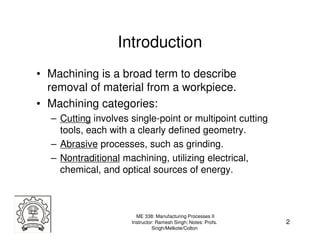
2. Introduction
• Machining is a broad term to describe
removal of material from a workpiece.
• Machining categories:
– Cutting involves single-point or multipoint cutting
tools, each with a clearly defined geometry.
– Abrasive processes, such as grinding.
– Nontraditional machining, utilizing electrical,
chemical, and optical sources of energy.
ME 338: Manufacturing Processes II
Instructor: Ramesh Singh; Notes: Profs. 2
Singh/Melkote/Colton
4. Traditional vs. Nontraditional
• Primary source of energy
– Traditional: mechanical.
– Nontraditional: electrical, chemical, optical
• Primary method of material removal
– Traditional: shearing
– Nontraditional: does not use shearing
(e.g., abrasive water jet cutting uses
erosion) Water jet machining
Grinding
2D cutting process
ME 338: Manufacturing Processes II
Instructor: Ramesh Singh; Notes: Profs. 4
Singh/Melkote/Colton
5. Why Nontraditional Machining?
• Situations where traditional machining processes are
unsatisfactory or uneconomical:
– Workpiece material is too hard, strong, or tough.
– Workpiece is too flexible to resist cutting forces or too difficult
to clamp.
– Part shape is very complex with internal or external profiles
or small holes.
– Requirements for surface finish and tolerances are very high.
– Temperature rise or residual stresses are undesirable or
unacceptable.
ME 338: Manufacturing Processes II
Instructor: Ramesh Singh; Notes: Profs. 5
Singh/Melkote/Colton
6. Ultrasonic Machining (USM)
• Process description
– The tool, which is negative of the
workpiece, is vibrated at low
amplitude (0.013 to 0.08 mm) and
high frequency (about 20 kHz) in an
abrasive grit slurry at the workpiece
surface.
– The slurry also carries away the
debris from the cutting area.
– The tool is gradually moved down
maintaining a constant gap of
approximately 0.1 mm between the
tool and workpiece surface.
ME 338: Manufacturing Processes II
Instructor: Ramesh Singh; Notes: Profs. 6
Singh/Melkote/Colton
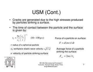
7. USM (Cont.)
• Cracks are generated due to the high stresses produced
by particles striking a surface.
• The time of contact between the particle and the surface
is given by:
1/ 5
5r c 0
t0 ≈ (10 − 100 µ s ) Force of a particle on surface:
c0 v
F = d (mv) / dt
r: radius of a spherical particle
c0: workpiece elastic wave velocity = E / ρ Average force of a particle
striking the surface:
v: velocity of particle striking surface
Fave = 2mv / t 0
ME 338: Manufacturing Processes II
Instructor: Ramesh Singh; Notes: Profs. 7
Singh/Melkote/Colton
8. USM (Cont.)
• Example: Explain what change, if any, takes place in the
magnitude of the impact force of a particle in ultrasonic
machining as the temperature of the workpiece is
increased.
Solution:
Here, m and v are constant.
1/ 5
5r c 0 1 1
t0 = ⇒ t0 ∝ ∝
c0 v c04 / 5 E 2/5
When temperature increases, E decreases
and t0 increases. Hence, F decreases.
ME 338: Manufacturing Processes II
Instructor: Ramesh Singh; Notes: Profs. 8
Singh/Melkote/Colton
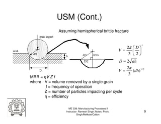
9. USM (Cont.)
Assuming hemispherical brittle fracture
3
2π D
V=
3 2
D ≈ 2 dh
2π
V= (dh) 3 / 2
3
MRR = ηV Z f
where V = volume removed by a single grain
f = frequency of operation
Z = number of particles impacting per cycle
η = efficiency
ME 338: Manufacturing Processes II
Instructor: Ramesh Singh; Notes: Profs. 9
Singh/Melkote/Colton
10. USM (Cont.)
• Applications
– USM is best suited for hard, brittle materials, such as ceramics,
carbides, glass, precious stones, and hardened steels. (Why?)
• Capability
– With fine abrasives, tolerance of 0.0125 mm or better can be held.
Ra varies between 0.2 – 1.6 µm.
• Pros & Cons:
– Pros: precise machining of brittle materials; makes tiny holes (0.3
mm); does not produce electric, thermal, chemical damage
because it removes material mechanically.
– Cons: low material removal rate (typically 0.8 cm3/min); tool wears
rapidly; machining area and depth are limited.
ME 338: Manufacturing Processes II
Instructor: Ramesh Singh; Notes: Profs. 10
Singh/Melkote/Colton
11. USM Parts
Ceramic
ME 338: Manufacturing Processes II
Instructor: Ramesh Singh; Notes: Profs. 11
Singh/Melkote/Colton
12. Water-Jet Machining (WJM)
also called hydrodynamic machining
WJM is a form of micro erosion. It The extreme pressure of the accelerated
works by forcing a large volume of water particles contacts a small area of the
water through a small orifice in the workpiece and acts like a saw and cuts a
nozzle. narrow groove in the material.
http://www.flowcorp.com/waterjet-resources.cfm?id=360
ME 338: Manufacturing Processes II
Instructor: Ramesh Singh; Notes: Profs. 12
Singh/Melkote/Colton
13. WJM (Cont.)
• Pros: no need for predrilled holes, no heat, no workpiece
deflection (hence suitable for flexible materials), minimal
burr, environmentally friendly.
• Cons: limited to material with naturally occurring small
cracks or softer material.
• Applications:
– Mostly used to cut lower strength materials such as wood,
plastics, rubber, paper, leather, composite, etc.
– Food preparation
– Good for materials that cannot withstand high temperatures of
other methods for stress distortion or metallurgical reasons.
ME 338: Manufacturing Processes II
Instructor: Ramesh Singh; Notes: Profs. 13
Singh/Melkote/Colton
14. WJM Examples
PWB (printed wire board)
ME 338: Manufacturing Processes II
Instructor: Ramesh Singh; Notes: Profs. 14
Singh/Melkote/Colton
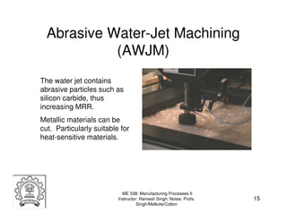
15. Abrasive Water-Jet Machining
(AWJM)
The water jet contains
abrasive particles such as
silicon carbide, thus
increasing MRR.
Metallic materials can be
cut. Particularly suitable for
heat-sensitive materials.
ME 338: Manufacturing Processes II
Instructor: Ramesh Singh; Notes: Profs. 15
Singh/Melkote/Colton
16. AWJM Parts
Bullet Proof Glass Part
Steel rack (75 mm thick)
Ceramic Part
Source: http://www.waterjets.org/
ME 338: Manufacturing Processes II
Instructor: Ramesh Singh; Notes: Profs. 16
Singh/Melkote/Colton
17. Abrasive-Jet Machining (AJM)
A high-velocity jet of dry air, The gas supply pressure is on
nitrogen, or carbon dioxide the order of 850 kPa (125 psi)
containing abrasive particles is and the jet velocity can be as
aimed at the workpiece surface high as 300 m/s and is
under controlled conditions. controlled by a valve.
ME 338: Manufacturing Processes II
Instructor: Ramesh Singh; Notes: Profs. 17
Singh/Melkote/Colton
18. AJM Process Capability
• Material removal
– Typical cutting speeds vary between 25 -125 mm/min
• Dimensional Tolerances
– Typical range ±2 - ±5 µm
• Surface Finish
– Typical Ra values vary from 0.3 - 2.3 µm
ME 338: Manufacturing Processes II
Instructor: Ramesh Singh; Notes: Profs. 18
Singh/Melkote/Colton
19. AJM Applications & Limitations
• Applications
– Can cut traditionally hard to cut materials, e.g., composites,
ceramics, glass
– Good for materials that cannot stand high temperatures
• Limitations
– Expensive process
– Flaring can become large
– Not suitable for mass production because of high
maintenance requirements
ME 338: Manufacturing Processes II
Instructor: Ramesh Singh; Notes: Profs. 19
Singh/Melkote/Colton
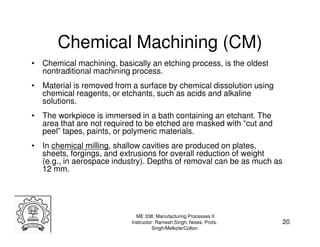
20. Chemical Machining (CM)
• Chemical machining, basically an etching process, is the oldest
nontraditional machining process.
• Material is removed from a surface by chemical dissolution using
chemical reagents, or etchants, such as acids and alkaline
solutions.
• The workpiece is immersed in a bath containing an etchant. The
area that are not required to be etched are masked with “cut and
peel” tapes, paints, or polymeric materials.
• In chemical milling, shallow cavities are produced on plates,
sheets, forgings, and extrusions for overall reduction of weight
(e.g., in aerospace industry). Depths of removal can be as much as
12 mm.
ME 338: Manufacturing Processes II
Instructor: Ramesh Singh; Notes: Profs. 20
Singh/Melkote/Colton
21. CM (Cont.)
• Chemical blanking is used to produce features which
penetrate through the material via chemical dissolution.
The metal that is to be blanked is
– thoroughly cleaned with solvents.
– coated and the image of the part is imprinted.
– soaked in a solvent that removes the coating, except in the
protected areas.
– spray etched to dissolve the unprotected areas and leave the
finished part.
ME 338: Manufacturing Processes II
Instructor: Ramesh Singh; Notes: Profs. 21
Singh/Melkote/Colton
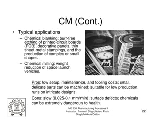
22. CM (Cont.)
• Typical applications
– Chemical blanking: burr-free
etching of printed-circuit boards
(PCB), decorative panels, thin
sheet-metal stampings, and the
production of complex or small
shapes.
– Chemical milling: weight
reduction of space launch
vehicles.
Pros: low setup, maintenance, and tooling costs; small,
delicate parts can be machined; suitable for low production
runs on intricate designs.
Cons: slow (0.025-0.1 mm/min); surface defects; chemicals
can be extremely dangerous to health.
ME 338: Manufacturing Processes II
Instructor: Ramesh Singh; Notes: Profs. 22
Singh/Melkote/Colton
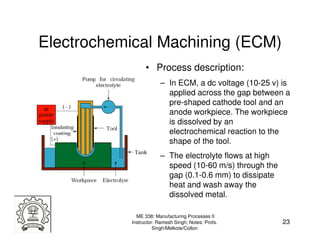
23. Electrochemical Machining (ECM)
• Process description:
– In ECM, a dc voltage (10-25 v) is
applied across the gap between a
pre-shaped cathode tool and an
anode workpiece. The workpiece
is dissolved by an
electrochemical reaction to the
shape of the tool.
– The electrolyte flows at high
speed (10-60 m/s) through the
gap (0.1-0.6 mm) to dissipate
heat and wash away the
dissolved metal.
ME 338: Manufacturing Processes II
Instructor: Ramesh Singh; Notes: Profs. 23
Singh/Melkote/Colton
24. ECM (Cont.)
• The material removal rate by ECM is given by:
MRR = C I η
where, MRR=mm3/min, I=current in amperes,
η=current efficiency, which typically ranges from 90-100%,
C is a material constant in mm3/A·min.
Feed rate (mm/min): f = MRR / A0
Assuming a cavity with uniform cross-sectional area A0
ME 338: Manufacturing Processes II
Instructor: Ramesh Singh; Notes: Profs. 24
Singh/Melkote/Colton
25. ECM (Cont.)
• Pros: high shape complexity
possible, high MRR possible, high-
strength materials, mirror surface
finish possible.
• Cons: workpiece must be
electrically conductive; very high
tooling (dedicated) and equipment
costs; high power consumption.
• Applications: complex cavities in
high-strength materials, esp. in
aerospace industry for mass
production of turbine blades.
ME 338: Manufacturing Processes II
Instructor: Ramesh Singh; Notes: Profs. 25
Singh/Melkote/Colton
26. EDM-History
ME 338: Manufacturing Processes II
Instructor: Ramesh Singh; Notes: Profs. 26
Singh/Melkote/Colton
27. Electrical Discharge Machining
(EDM)
EDM is a thermal erosion
process whereby material
is melted and vaporized
from an electrically
conducive workpiece
immersed in a liquid
dielectric with a series of
spark discharges between
the tool electrode and the
workpiece created by a
power supply.
EDM is one of the most accurate
while quite affordable mfg process.
ME 338: Manufacturing Processes II
Instructor: Ramesh Singh; Notes: Profs. 27
Singh/Melkote/Colton
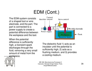
28. EDM (Cont.)
The EDM system consists
of a shaped tool or wire
electrode, and the part. The
part is connected to a
power supply to create a
potential difference between
the workpiece and the tool.
When the potential
difference is sufficiently
high, a transient spark The dielectric fluid 1) acts as an
discharges through the insulator until the potential is
fluid, removing a very small sufficiently high, 2) acts as a
amount of metal from the flushing medium, and 3) provides
workpiece. a cooling medium.
ME 338: Manufacturing Processes II
Instructor: Ramesh Singh; Notes: Profs. 28
Singh/Melkote/Colton
29. Process-Basics
ME 338: Manufacturing Processes II
Instructor: Ramesh Singh; Notes: Profs. 29
Singh/Melkote/Colton
30. EDM (Cont.)
MRR is basically a function of the current and the melting point of
the workpiece material. An approximate empirical relationship is:
4 −1.23 MRR=mm3/min
MRR = 4 × 10 I T w
I=current in amperes
Tw=melting point of workpiece (ºC)
Wear rate of electrode:
Wt = 11× 10 3 I Tt −2.38 Wear ratio of workpiece
to electrode:
Wt=mm3/min
Tt=melting point of electrode material (ºC) R = 2.25 Tr−2.3
Tr=ratio of workpiece to
electrode melting points (ºC)
ME 338: Manufacturing Processes II
Instructor: Ramesh Singh; Notes: Profs. 30
Singh/Melkote/Colton
31. MRR - EDM
Metal removal is function of pulse energy
• Experimental Approach
and frequency:
h = K1Wn
TOOL
(-) D= K2Wn
where W = Pulse energy, J
DC VOLTAGE
h = height of crater, mm
D = diameter of crater, mm
K1, K2 = constants depending
h on electrode materials
D and dielectric
n = constant depending on
WORKPIECE work tool combination
(+) The crater volume from geometry,
π 3
Scheme of Crater Formation Vc = h D 2 + h 2
6 4
MRR = Vc f η π 3 2 2 3n
where f = frequency of operation and η = efficiency Vc = K1 K 2 + K1 W
6 4
ME 338: Manufacturing Processes II
Instructor: Ramesh Singh; Notes: Profs. 31
Singh/Melkote/Colton
32. Volume of the crater
ME 338: Manufacturing Processes II
Instructor: Ramesh Singh; Notes: Profs. 32
Singh/Melkote/Colton
33. EDM Process Capability
• MRR
– Range from 2 to 400 mm3/min. High rates produce rough finish,
having a molten and recast structure with poor surface integrity
and low fatigue properties.
• Dimensional Tolerances
– Function of the material being processed
– Typically between ±0.005 - ±0.125 mm
• Surface Finish
– Depends on current density and material being machined
– Ra varies from 0.05 – 12.5 µm
– New techniques use an oscillating electrode, providing very fine
surface finishes.
ME 338: Manufacturing Processes II
Instructor: Ramesh Singh; Notes: Profs. 33
Singh/Melkote/Colton
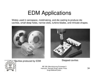
34. EDM Applications
Widely used in aerospace, moldmaking, and die casting to produce die
cavities, small deep holes, narrow slots, turbine blades, and intricate shapes.
Cavities produced by EDM Stepped cavities
ME 338: Manufacturing Processes II
Instructor: Ramesh Singh; Notes: Profs. 34
Singh/Melkote/Colton
35. EDM Limitations
• Limitations
– A hard skin, or recast layer is produced which may be
undesirable in some cases.
– Beneath the recast layer is a heat affected zone which
may be softer than parent material.
– Finishing cuts are needed at low MRR.
– Produces slightly tapered holes, specially if blind.
ME 338: Manufacturing Processes II
Instructor: Ramesh Singh; Notes: Profs. 35
Singh/Melkote/Colton
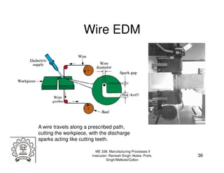
36. Wire EDM
A wire travels along a prescribed path,
cutting the workpiece, with the discharge
sparks acting like cutting teeth.
ME 338: Manufacturing Processes II
Instructor: Ramesh Singh; Notes: Profs. 36
Singh/Melkote/Colton
37. Wire EDM (Cont.)
MRR in Wire EDM
MRR = V f h b
where, b = d w + 2s
MRR = mm3/min
Vf = feed rate of wire into the
workpiece in mm/min
h = workpiece thickness or dw = wire diameter in mm
height in mm s = gap between wire and workpiece in mm
ME 338: Manufacturing Processes II
Instructor: Ramesh Singh; Notes: Profs. 37
Singh/Melkote/Colton
38. Wire EDM Parts
ME 338: Manufacturing Processes II
Instructor: Ramesh Singh; Notes: Profs. 38
Singh/Melkote/Colton
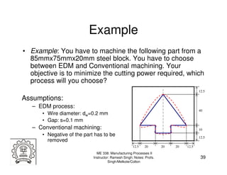
39. Example
• Example: You have to machine the following part from a
85mmx75mmx20mm steel block. You have to choose
between EDM and Conventional machining. Your
objective is to minimize the cutting power required, which
process will you choose?
12.5
Assumptions:
– EDM process:
40
• Wire diameter: dw=0.2 mm
• Gap: s=0.1 mm
– Conventional machining: 10
• Negative of the part has to be 12.5
removed
12.5 20 20 20 12.5
ME 338: Manufacturing Processes II
Instructor: Ramesh Singh; Notes: Profs. 39
Singh/Melkote/Colton
40. Example
Solution:
- EDM process
VEDM = lc*(dw+2s)*t = 1440 mm3
- Conventional machining
VM= Vtotal – Vpart = 99500 mm3
- Power comparison
u M VM u EDM VEDM
We will choose machining if ≤
tM t EDM
let’s assume tEDM=αtM
u EDM VEDM
then machining if α ≤
u M VM
ME 338: Manufacturing Processes II
Instructor: Ramesh Singh; Notes: Profs. 40
Singh/Melkote/Colton
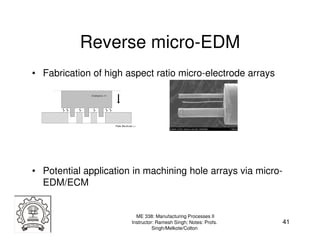
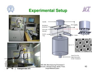
41. Reverse micro-EDM
• Fabrication of high aspect ratio micro-electrode arrays
• Potential application in machining hole arrays via micro-
EDM/ECM
ME 338: Manufacturing Processes II
Instructor: Ramesh Singh; Notes: Profs. 41
Singh/Melkote/Colton
42. Arrays Fabricated via R µ-EDM @IITB
6x6 array 4x4 array
ME 338: Manufacturing Processes II
Instructor: Ramesh Singh; Notes: Profs. 42
Singh/Melkote/Colton
43. Experimental Setup
ME 338: Manufacturing Processes II
Instructor: Ramesh Singh; Notes: Profs. 43
Singh/Melkote/Colton
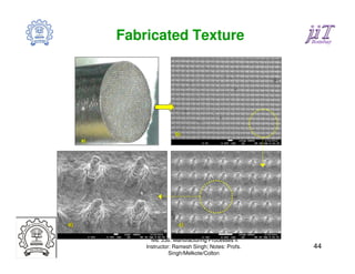
44. Fabricated Texture
ME 338: Manufacturing Processes II
Instructor: Ramesh Singh; Notes: Profs. 44
Singh/Melkote/Colton
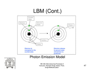
46. Laser-Beam Machining (LBM)
• Laser Concept
– Add energy to make electrons “jump” to higher energy orbit
– Electron “relaxes” and moves to equilibrium at ground-state
energy level
– Emits a photon in this process (key laser component)
– Two mirrors reflect the photons back and forth and “excite” more
electrons
– One mirror is partially reflective to allow some light to pass
through: creates narrow laser beam
ME 338: Manufacturing Processes II
Instructor: Ramesh Singh; Notes: Profs. 46
Singh/Melkote/Colton
47. LBM (Cont.)
Excited
State
Electron Ground
State Photon
Nucleus
Orbits
Electron is Electron relaxes
energized to the to ground state
excited state and photon is
produced
Photon Emission Model
ME 338: Manufacturing Processes II
Instructor: Ramesh Singh; Notes: Profs. 47
Singh/Melkote/Colton
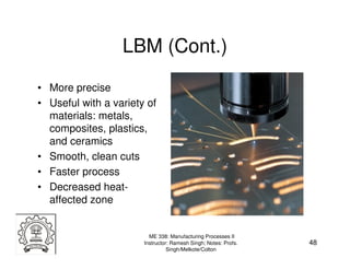
48. LBM (Cont.)
• More precise
• Useful with a variety of
materials: metals,
composites, plastics,
and ceramics
• Smooth, clean cuts
• Faster process
• Decreased heat-
affected zone
ME 338: Manufacturing Processes II
Instructor: Ramesh Singh; Notes: Profs. 48
Singh/Melkote/Colton
49. Schematic of LBM Device
ME 338: Manufacturing Processes II
Instructor: Ramesh Singh; Notes: Profs. 49
Singh/Melkote/Colton
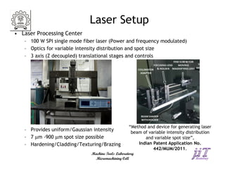
50. Laser Setup
• Laser Processing Center
– 100 W SPI single mode fiber laser (Power and frequency modulated)
– Optics for variable intensity distribution and spot size
– 3 axis (Z decoupled) translational stages and controls
“Method and device for generating laser
– Provides uniform/Gaussian intensity beam of variable intensity distribution
– 7 µm -900 µm spot size possible and variable spot size”,
– Hardening/Cladding/Texturing/Brazing Indian Patent Application No.
442/MUM/2011.
Machine Tools Laboratory
Micromachining Cell
51. LBM (Cont.)
• Important physical parameters in LBM
– Reflectivity
– Thermal conductivity of workpiece surface
– Specific heat and latent heats of melting and evaporation
• The lower these quantities, the more efficient the
process.
• The cutting depth t: t = P / vd
P is the power input, v is the cutting speed,
and d is the laser-beam-spot diameter.
ME 338: Manufacturing Processes II
Instructor: Ramesh Singh; Notes: Profs. 51
Singh/Melkote/Colton
52. Heat Source Modeling
• Solution for stationary point using Green’s Theorem:
The differential equation for the conduction of heat in a
stationary medium assuming no convection or radiation, is
This is satisfied by the solution for infinite body,
δq ( x − x ') 2 + ( y − y ') 2 + ( z − z ') 2
dT '( x, y, z, t ) = 3
ex p [ − ]
4 a ( t − t ')
ρ C (4 π a ( t − t ')) 2
sem i − in f in ite
2δ q ( x − x ') 2 + ( y − y ') 2 + ( z − z ') 2
dT '( x, y, z, t ) = 3
ex p [ − ]
4 a ( t − t ')
ρ C (4 π a ( t − t ')) 2
δq = instantaneous heat generated, C = sp. heat capacity, α =
diffusivity, ρ = Density, t = time, K = thermal conductivity.
gives the temperature increment at position (x, y, z) and time
t due to an instantaneous heat source δq applied at position
(x’, y’, z’) and time t’. ME 338: Manufacturing Processes II
Instructor: Ramesh Singh; Notes: Profs. 52
Singh/Melkote/Colton
53. Moving point heat source in semi-infinite body
In moving coordinate system:
2δ q ( X − x ') 2 + (Y − y ') 2 + ( Z − z ') 2
dT '( x, y, z, t ) = 3
exp [ − ]
4 a ( t − t ')
ρ C (4 π a ( t − t ')) 2
In fixed coordinate system:
2δ q ( x − vt '− x ') 2 + ( y − y ') 2 + ( z − z ') 2
dT '( x, y, z, t ) = 3
ex p [ − ]
4 a ( t − t ')
ρ C (4 π a ( t − t ')) 2
Note that δ q = Pdt ' ME 338: Manufacturing Processes II
Instructor: Ramesh Singh; Notes: Profs. 53
Singh/Melkote/Colton
54. Moving point heat source:
Consider point heat source P heat units per unit time moving with velocity v on semi-
infinite body from time t’= 0 to t’= t. During a very short time heat released at the
surface is dQ = Pdt’. This will result in infinitesimal rise in temperature at point (x, y, z)
at time t given by,
t '= t
2 Pdt ' ( x − vt '− x ') 2 + ( y − y ') 2 + ( z − z ') 2
dT '( x, y, z, t ) = ∫
t '= 0
3
ex p [ −
4 a ( t − t ')
]
ρ C (4 π a ( t − t ')) 2
The total rise in of the temperature can be obtained by
integrating from t’=0 to t’= t
55. Gaussian Circular
• Gaussian beam distribution
2P 2( x '2 + y '2 )
I ( x ', y ') = 2
exp[− 2
]
πσ σ
• Gaussian circular heat source
2dt ' ( X − x ') 2 + (Y − y ') 2 + ( Z − z ') 2
dT '( X , Y , Z , t ) = 3
I ( x ', y ')dx ' dy 'exp[− ]
4a(t − t ')
ρ C (4π a(t − t ')) 2
∞ ∞
2dt ' 2P 2( x '2 + y '2 ) ( X − x ')2 + (Y − y ')2 + ( Z − z ')2
dT ' = 3
πσ 2 ∫ ∫
−∞ −∞
exp[−
σ2
]dx ' dy 'exp[−
4a(t − t ')
]
ρ C (4π a(t − t ')) 2
In fixed coordinate sytem
t '= t
4P dt '(t − t ') −0.5 2(( x − vt ') 2 + y 2 ) z2
T − T0 =
ρ C π 4 aπ ∫0 σ 2 + 8a (t − t ') exp[ − σ 2 + 8a (t − t ') − 4 a (t − t ') ]
t '=
ME 338: Manufacturing Processes II
Instructor: Ramesh Singh; Notes: Profs. 55
Singh/Melkote/Colton
56. Uniform Circular/Rectangular
• Circular
t σ
2P dt ' (( x − vt ') − x ') 2
T − T0 =
8 π 2σ 2 K ∫
0
( t − t ') ∫
−σ
ex p [ −
4 a ( t − t ')
]d x ' ×
y − σ 2 − x '2 y + σ 2 − x '2
[ − erf ( ) + erf ( )]
2 a ( t − t ') 2 a ( t − t ')
• Rectangular
2δ q d t ' z2
T − T0 = 3
exp[− ]
4 a ( t − t ')
4 b l ρ C ( 4 π a ( t − t ') ) 2
l b
( ( x − v t ') − x ') 2 ( y − y ') 2
∫l
−
exp[−
4 a ( t − t ')
]d x ' ∫ e x p [ −
−b
4 a ( t − t ')
]d y '
ME 338: Manufacturing Processes II
Instructor: Ramesh Singh; Notes: Profs. 56
Singh/Melkote/Colton
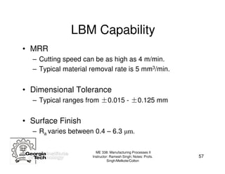
57. LBM Capability
• MRR
– Cutting speed can be as high as 4 m/min.
– Typical material removal rate is 5 mm3/min.
• Dimensional Tolerance
– Typical ranges from ±0.015 - ±0.125 mm
• Surface Finish
– Ra varies between 0.4 – 6.3 µm.
ME 338: Manufacturing Processes II
Instructor: Ramesh Singh; Notes: Profs. 57
Singh/Melkote/Colton
58. LBM (Cont.)
• Process Variations
– Laser beam machines can be used for cutting, surface hardening,
welding, drilling, blanking, engraving and trimming.
– Types of lasers used: pulsed and CW CO2, Nd:YAG, Nd:glass,
ruby and excimer.
– High-pressure gas streams are used to enhance the process by
aiding the exothermic reaction process, to cool and blow away the
vaporized or molten material and slag.
ME 338: Manufacturing Processes II
Instructor: Ramesh Singh; Notes: Profs. 58
Singh/Melkote/Colton
59. LBM (Cont.)
• Applications
– Multiple holes in very thin and thick materials
– Non-standard shaped holes and slots
– Prototype parts
– Trimming, scribing and engraving of hard materials
– Small diameter lubrication holes
• Limitations
– Localized thermal stresses, heat affected zones, recast layer and
thermal distribution in thin parts
– Difficulty of material processing depends on how close materials
boiling and melting points are
– Hole wall geometry can be irregular
– The cutting of flammable materials is usually inert gas assisted
ME 338: Manufacturing Processes II
Instructor: Ramesh Singh; Notes: Profs. 59
Singh/Melkote/Colton
60. Electron-Beam Machining (EBM)
How it Works
• A stream of electrons is started by
a voltage differential at the
cathode. The concave shape of
the cathode grid concentrates the
stream through the anode.
• The anode applies a potential field
that accelerates the electrons.
• The electron stream is then forced
through a valve in the electron
beam machine.
• The beam is focused onto the
surface of the work material,
heating, melting, and vaporizing
the material.
ME 338: Manufacturing Processes II
Instructor: Ramesh Singh; Notes: Profs. 60
Singh/Melkote/Colton
61. EBM (Cont.)
The entire process occurs in a vacuum chamber because a collision
between an electron and an air molecule causes the electrons to veer
off course. LBM doesn’t need vacuum because the size and mass of a
photon is numerous times smaller than the size of an electron.
ME 338: Manufacturing Processes II
Instructor: Ramesh Singh; Notes: Profs. 61
Singh/Melkote/Colton
62. EBM Characteristics
• Mechanics of material removal – melting, vaporization
• Medium – vacuum
• Tool – beam of electrons moving at very high velocity
• Maximum MRR = 10 mm3/min
• Specific power consumption = 450 W/mm3/min
• Critical parameters – accelerating voltage, beam
diameter, work speed, melting temperature
• Materials application – all materials
• Shape application – drilling fine holes, cutting contours in
sheets, cutting narrow slots
• Limitations – very high specific energy consumption,
necessity of vacuum, expensive machine
ME 338: Manufacturing Processes II
Instructor: Ramesh Singh; Notes: Profs. 62
Singh/Melkote/Colton
63. Comparative Performance
ME 338: Manufacturing Processes II
Instructor: Ramesh Singh; Notes: Profs. 63
Singh/Melkote/Colton
64. Focused Ion Beam Technologies
• Ga+ ion beam raster over the
surface similar to SEM
• Milling of small holes and
modifications in the structures
can be done
• Most instruments combine
nowadays a SEM and FIB for
imaging with high resolution,
and accurate control of the
progress of the milling
• Process is performed in
vacuum
ME 338: Manufacturing Processes II
Instructor: Ramesh Singh; Notes: Profs. 64
Singh/Melkote/Colton
65. Mechanism
Rate of etch depth
Where, Y is sputter yield of surface atoms per
incoming ion, using a probe of current I is given by
A is the etched area, ρ is the density of target
material, M is atomic mass of target material and
e is charge
ME 338: Manufacturing Processes II
Instructor: Ramesh Singh; Notes: Profs. 65
Singh/Melkote/Colton
66. Dual Beam System
ME 338: Manufacturing Processes II
Instructor: Ramesh Singh; Notes: Profs. 66
Singh/Melkote/Colton
67. ME 338: Manufacturing Processes II
Instructor: Ramesh Singh; Notes: Profs. 67
Singh/Melkote/Colton
68. Focused Ion Beam Technologies
• FIB finds application in:
– Ablation of hard materials:
diamond, WC
– Polishing of single crystals
– Deposition
– Site-specific analysis
– FIB lithography
– TEM samples
• Capital investment ~ 5 Crore
ME 338: Manufacturing Processes II
Instructor: Ramesh Singh; Notes: Profs. 68
Singh/Melkote/Colton
69. Process Capabilities of FIB
• Deposition
• Etching
• Low material removal
• Very high cost
• Nanometric imaging resolution
• Can process conducting and non conducting materials
ME 338: Manufacturing Processes II
Instructor: Ramesh Singh; Notes: Profs. 69
Singh/Melkote/Colton
70. Summary
• Process description and capability
– Ultrasonic Machining (USM)
– Water-Jet Machining & Abrasive-Jet Machining
– Chemical Machining
– Electrochemical Machining (ECM)
– Electrical-Discharge Machining (EDM)
• High-Energy-Beam Machining
– Laser-beam machining (LBM)
– Electron-beam machining (EBM)
– Focused Ion Beam (FIB)
ME 338: Manufacturing Processes II
Instructor: Ramesh Singh; Notes: Profs. 70
Singh/Melkote/Colton