1 reboilers types
•Download as DOCX, PDF•
9 likes•4,534 views
A reboiler is a heat exchanger that provides heat to the bottom of a distillation column. There are several types of reboilers including kettle reboilers, thermosyphon reboilers, fired reboilers, and forced circulation reboilers. Kettle reboilers are simple devices where steam flows through tubes in a shell to heat liquid in the shell. Thermosyphon reboilers use density differences to circulate liquid without pumps. Fired reboilers use combustion to heat liquid circulating through tubes. Forced circulation reboilers use pumps to circulate liquid through shell and tube heat exchangers.
Report
Share

1 reboilers types
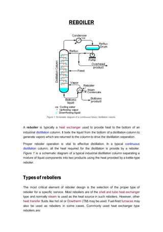
- 1. REBOILER Figure 1: Schematic diagram of a continuous binary distillation column. A reboiler is typically a heat exchanger used to provide heat to the bottom of an industrial distillation column. It boils the liquid from the bottom of a distillation column to generate vapors which are returned to the column to drive the distillation separation. Proper reboiler operation is vital to effective distillation. In a typical continuous distillation column, all the heat required for the distillation is provide by a reboiler. Figure 1 is a schematic diagram of a typical industrial distillation column separating a mixture of liquid components into two products using the heat provided by a kettle-type reboiler. Types of reboilers The most critical element of reboiler design is the selection of the proper type of reboiler for a specific service. Most reboilers are of the shell and tube heat exchanger type and normally steam is used as the heat source in such reboilers. However, other heat transfer fluids like hot oil or Dowtherm (TM) may be used. Fuel-fired furnaces may also be used as reboilers in some cases. Commonly used heat exchanger type reboilers are:
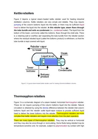
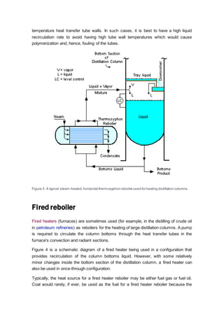
- 2. Kettlereboilers Figure 2 depicts a typical steam-heated kettle reboiler used for heating industrial distillation columns. Kettle reboilers are very simple and reliable. They may require pumping of the column bottoms liquid into the kettle, or there may be sufficient liquid head to deliver the liquid into the reboiler. In this reboiler type, steam flows through the tube bundle and exits as condensate (i.e., condensed water). The liquid from the bottom of the tower, commonly called the bottoms, flows through the shell side. There is a retaining wall or overflow weir separating the tube bundle from the reboiler section where the residual reboiled liquid (called the bottoms product) is withdrawn, so that the tube bundle is kept covered with liquid. Figure 2: A typical steam-heated kettle reboiler used for heating industrial distillation columns. Thermosyphon reboilers Figure 3 is a schematic diagram of a steam-heated, horizontal thermosyphon reboiler. These do not require pumping of the column bottoms liquid into the reboiler. Natural circulation is obtained by using the density difference between the reboiler inlet column bottoms liquid and the reboiler outlet liquid-vapor mixture to provide sufficient liquid head to deliver the tower bottoms into the reboiler. Thermosyphon reboilers are more complex than kettle reboilers and require more attention from the plant operators. There are many types of thermosyphon reboilers. They may be vertical or horizontal and they may also be once-through or recirculating. Some fluids being reboiled may be temperature-sensitive and, for example, subject to polymerization by contact with high
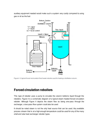
- 3. temperature heat transfer tube walls. In such cases, it is best to have a high liquid recirculation rate to avoid having high tube wall temperatures which would cause polymerization and, hence, fouling of the tubes. Figure 3: A typical steam-heated,horizontal thermosyphon reboiler used for heating distillation columns. Fired reboiler Fired heaters (furnaces) are sometimes used (for example, in the distilling of crude oil in petroleum refineries) as reboilers for the heating of large distillation columns. A pump is required to circulate the column bottoms through the heat transfer tubes in the furnace's convection and radiant sections. Figure 4 is a schematic diagram of a fired heater being used in a configuration that provides recirculation of the column bottoms liquid. However, with some relatively minor changes inside the bottom section of the distillation column, a fired heater can also be used in once-through configuration. Typically, the heat source for a fired heater reboiler may be either fuel gas or fuel oil. Coal would rarely, if ever, be used as the fuel for a fired heater reboiler because the
- 4. auxiliary equipment needed would make such a system very costly compared to using gas or oil as the fuel. Figure 4: A typical forced recirculation fired heater reboiler used for heating a distillation column. Forced circulation reboilers This type of reboiler uses a pump to circulate the column bottoms liquid through the reboilers. Figure 4 is a schematic diagram of a typical steam-heated forced circulation reboiler. Although Figure 4 depicts the steam flow as being one-pass through the exchanger, a two-pass flow system could also be used It should be noted steam is not the only heat source that can be used. Any available process stream that is at a high enough temperature could be used for any of the many shell and tube heat exchanger reboiler types.
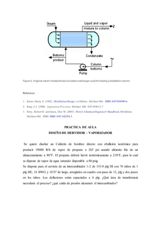
- 5. Figure 5: A typical steam-heated forced circulation exchanger used for heating a distillation column. References 1. Kister, Henry Z. (1992). Distillation Design, 1st Edition. McGraw-Hill. ISBN 0-07-034909-6. 2. King, C.J. (1980). Separation Processes. McGraw Hill. 0-07-034612-7. 3. Perry, Robert H. and Green, Don W. (2007). Perry's Chemical Engineers' Handbook,8th Edition. McGraw-Hill. ISBN ISBN 0-07-142294-3. PRACTICA DE AULA DISEÑO DE HERVIDOR – VAPORIZADOR Se quiere diseñar un Calderin de bombeo directo con ebullición isotérmica para producir 18000 lb/h de vapor de propano a 265 psi usando alimento frío de un almacenamiento a 80°F. El propano deberá hervir isotérmicamente a 210°F, para lo cual se dispone de vapor de agua saturado disponible a 80 psig. Se dispone para el servicio de un intercambiador 1-2 de 151/4 plg DI con 76 tubos de 1 plg DE, 16 BWG y 16’0” de largo, arreglados en cuadro con paso de 12, plg y dos pasos en los tubos. Los deflectores están espaciados a 6 plg. ¿Qué área de transferencia necesitará el proceso? ¿qué caída de presión alcanzará el intercambiador?